Design and Manufacturing of A Benchtop Thermoforming Machine By
Akwasi Owusu-Akyaw
Submitted to the Department of Mechanical Engineering In Partial Fulfillment of the Requirements for the Degree of
Bachelor of Science in Mechanical Engineering
at the
Massachusetts Institute of Technology June 2017
C 2017 Akwasi Owusu-Akyaw All Rights Reserved
The author hereby grants to MIT permission to reproduce and distribute publicly paper and electronic copies of this thesis document in whole or in part
in any medium now known or hereafter created.
Signature of Author: Certified by: Accepted by:
Signature redacted
Signature redacted.
Signature redacted
Department of Mechanical Engineering June, 2017
David E. Hardt Professor of Mechanical Engineering Thesis Supervisor Rohit Karnik
Professor of Mechanical Engineering
OF TECHNOLOGY,
JUL25 ?2017
Design and Manufacturing of a Benchtop Thermoforming Machine By
Akwasi Owusu-Akyaw
Submitted to the Department of Mechanical Engineering on June 2017 In Partial Fulfillment of the Requirements for the Degree of
Bachelor of Science in Mechanical Engineering ABSTRACT
The following work details the design and fabrication of a tabletop thermoform machine with the goal of making this machine cheaper than the ones on the market, yet able to fulfill specific requirements. These functional requirements include creating parts that have dimensions within .05" of the original part; thermoforming plastics that range between a 3" x 3" and 12" x 12" size; and having the ability to heat the plastic to at least 150'C in order to thermoform plastics such as polycarbonate. In addition, this machine
had to be simple to manufacture and use.
In order to achieve these requirements, a top to bottom drape forming architecture with a four bar linear slider and carriage, was constructed. In order to constrain the plastics of different sizes, two similar, modular wooden plates were used such that the plastic was held in between them via t-nuts and screws. When the user clamps the plastic onto the carriage, he or she slides the carriage upwards to an oven that radiates heat via nichrome wire on a mica sheet. Once the desired temperature is reached, the user then
slides the carriage down onto a vacuum box platform, where a mold is present, and forms the plastic over the mold. While that happens, a negative pressure is applied inside the box via a standard commercial vacuum, so that the plastic adheres more closely to the mold.
For the testing process, this work focuses on two manufacturing strategies for thermoforming parts: heating the air to the glass transition temperature before thermoforming, and heating the plastic to the glass transition temperature before thermoforming. Once this test was performed, the dimension of
each plastic part was examined in order to see if the tolerance levels were reached. In addition, this test determined whether or not there was a statistical significance between the qualities of parts made by either of these processes.
In the end, the thermoform machine was only able to reach an average tolerance of .07" for the created parts. In addition, there was no statistical significance between the part qualities of either one of the tested manufacturing processes. Some of the main reasons behind this include having an ineffective vacuum box and clamp design issues, which will be focused on in the future iteration of this project. Thesis Supervisor: David E Hardt
ACKNOWLEDGEMENTS
The author would like to thank his thesis supervisor Professor David Hardt for his continual support in completing this project, whether it was with design concepts or thesis documentation structure. In addition, he would like to acknowledge Mr. David Orozco and GenOne LLC in Cambridge, MA for proposing this thesis idea and providing pecuniary support for the completion of this project. As for the manufacturing of the machine, the author would like to thank the machine shops in MIT D-Lab, Hobby shop, and MITERS for providing the necessary tools for fabrication.TABLE OF CONTENTS
Intro du ction ... 8
1.1 B ackground ... 8
1.2 Theory of Process... 9
1.3 Thermoforming Scale... 10
1.3.1 Mass Production Scale... 10
1.3.2 Prototyping Scale... 11
Requirements and Strategy... 12
2.1 Functional Requirements... 12 2.2 Additional Requirements... 12 2.3 Strategies... 12 Mechanical Design... ... 14 3 .1 Structure ... 15 3 .2 O v en ... 15 3.3 V acuum B ox ... 2 1 3.4 Slider and Carriage... 22
3 .5 C lam p ... 2 3 E lectrical D esign ... ... ... ... 25 4 .1 S trategy ... 25 4.2 C ircuit L ayout... ... 26 F abrication ... ... 27 5.1 Structure... ... ... 27 5 .2 O v en ... 2 9
5.4 Slider and C arriage... 30 5 .5 C lam p ... . . 3 1 T estin g ... 3 2 6.1 O bjective... 32 6.2 P rocedure... 32 6 .3 A n aly sis... 34 6.4 C onclusion ... 35 Future W ork... 37 7.1 Further M odifications... 37 R eferences... . 38
LIST OF FIGURES
Figure 1: Typical thermoforming process with heater and vacuum chamber.[1]... 10Figure 2: Thermoforming Machine for Mass Production[2]... 10
Figure 3: (a) Centroform EZFORM Machine[3] and (b) ProForm Vacuum Former[4]... 11
Figure 4: (a) Preliminary ideas for thermoform design. (a) One design consists of translational motion between the oven and the mold. (b) The other design transports the plastic between the heater and the mold via rotation. The black arrows represent the motion of the plastic between the oven and vacuum b o x ... . . .. 13
Figure 5: Overall 3D model of thermoform machine... 14
Figure 6: Overall frame of the thermoform machine with L-brackets...15
Figure 7: Icarus crossing layout with numbers showing nichrome path... 16
Figure 8: Side View of Oven With Component Directions... 17
Figure 9: 1 -D Thermal resistance map of oven for thermoforming machine...20
Figure 10: Vacuum Box Design With Small Hole Array...22
iure 1: Slider - at one corner of e f . m.hin...23
Figure 13: Two plate clamping system for holding plastic between plates via wing nuts...24
Figure 14: (a) TRIAC circuit symbol with usual form of component in circuit. (b) TRIAC operation theory. Pulses are sent to the TRIAC at every zero crossing, so that power continually flows to the load. These pulses can be delayed so that the power delivered is modulated...25
Figure 15: (a) Circuit layout for heater controller with the following components: thermocouple (green), heater output (pink), temperature display (blue), and microcontroller (orange)...26
Figure 16: (a) straightening plywood for laser cutter manufacturing; (b) laser cutting of vacuum box top with weights that were used to straighten the wood; (c) laser cutting of oven wall section without weights; (d) laser cutting of mica sheet, which was possible due to the thinness of the sheet and the concentrated energy of the laser cutter...27
Figure 17: (a) holes drilled for 1-bracket bar, which allowed for multiple 1-brackets to be formed as shown in figures (b) and (c). After this machining, the brackets were cut out using a horizontal band saw, but the machine's low accuracy varied the heights of the 1-brackets...28
Figure 18: (a) connection between longer L-brackets and wider ones via 8-32 screws. This pattern was used in order to create the overall structure (as shown in (b))...29
Figure 19: (a) Oven box outer casing and (b) nichrome wire layout on mica sheet (note that the sheet metal has been taken off in order to show all sides of the insulation clearly)...29
Figure 20: Thermoform with 4 slider axles installed. These axles were held into place using an M6 set screw and lubricated with lithium grease for decreasing friction. As a note, the L-brackets were taken off for clarity ... . . 30
Figure 21: Carriage with Flat Plate Clamps and T-Nuts...31
Figure 22: Aluminum Mold Used for Testing...32
Figure 23: Thermoform Machine With Testing Devices...34
Figure 24: (a) Output Parts from Thermoform Machine With Top Forming; (b) Surface dimensions taken fo r d ata ... 3 5 Figure 25: Improved Design Idea with Raised Platforms...37
1
INTRODUCTION
1.1
Background
In the manufacturing world, there are many processes used in order to shape materials to one's desired shape and properties. One of those tools is a thermoforming. This technique was created during the 1930's in order to be used for manufacturing acrylic airplane canopies during World War II. In the present day manufacturing world, this process is used to produce other products such as cups, masks, and
packaging covers. Although this process produces parts with larger tolerance ranges than injection molding, one of the main advantages of thermoforming is that less tooling parts are needed for operation. Therefore, if the user requires a part that can be easily made but does not require tight tolerances, than thermoforming can be a more viable, cost-effective option to utilize.
Thermoforming is a manufacturing process where one takes a thermoplastic heated to the glass transition temperature and wraps it around a mold (usually made of metal). By doing this, the user is able to create a plastic part that is of similar shape to the mold used. The goal of this project is to recreate this process, but in a smaller, benchtop sized machine instead of the typical, large scaled ones used for
manufacturing.
The end use for this design would be for repeatedly creating plastic parts that would be used in proof of concept prototypes as structural or aesthetic parts. Although repeatability will be stressed, the need for accuracy is not as important because these parts would only be used for proof of concept designs.
Therefore, the overall goal is to create parts that double of the manufacturing tolerances used by many thermoforming manufacturers. Usually, manufacturers aim for a goal of .020" tolerance for each
dimension of a thermoformed part, however for this project, the aim is for .050" tolerance.
In addition to getting to the right tolerance level, the other goal is to make this thermoform machine have a better performance to cost ratio than other benchtop machines in the market. Other machines of similar size to this one have a cost of about $1500 and can usually thermoform sheets larger than 12" x 12". Although the desired machine in this project will have larger tolerances than these more expensive machines, the design WilI also encompass the ability to change the sheet size used for thermoforming, which is advantageous for forming different sized sheets. In the end, the performance to cost ratio of this
design would be more beneficial to someone who would utilize this machine for proof of concept prototypes.
An additional part of this project that is planned to be explored is the quality of the parts that can be outputted from the machine given that the user measures either air temperature around the plastic or the plastic temperature itself. Specifically, the aspect that will be explored is whether or not there is a statistically significant difference between the qualities of the parts formed given the two methods of measuring temperature.
1.2
Theory of Process
The theory of thermoforming is as follows:
1. A thermoplastic such as polystyrene or polycarbonate is clamped onto a frame, placed in an oven, and heated to the glass transition temperature, where it becomes very easy to deform. 2. Once the plastic is heated to the glass transition point, it is placed and formed onto a mold
(usually plastic).
3. In order to improve the plastic's ability to form around the mold, a positive or negative pressure is applied onto the plastic so that the heated piece conforms to the mold. This pressure application is usually done via air and also acts as a method for cooling the plastic. 4. Once the plastic is cooled, the part is taken out of the clamping system so that the excess
plastic is trimmed off of the part.
5. Once trimmed, the part can be used for its desired function.
Figure 1 shows one way of completing the above process via an assembly line fashion. Many industries use this streamline configuration in order to mass produce thermoplastic parts for consumers.
Thermoforming Principle
Heated Plastic Sheet 4- Positive Mould
Vacuum Drawn
Figure 1: Typical thermoforming process with heater and vacuum chamber.[1]
1.3
Thermoforming Scale
There are usually two scales of thermoforming that people tend to work with: mass production scale and prototyping scale.
1.3.1 Mass Production Scale
Typical large scaled machines for thermoforming mass production are shown in Figure 2. These machines usually have a large roll of plastic which is fed into the oven and quickly heated to the glass transition state. After that, the plastic then moves on to a mold with multiple versions of the same part, and quickly performs the thermoforming process. Once this is complete, another machine is used to cut off excess plastic from the parts.
1.3.2 Prototyping Scale
The other scale of thermoforming (and the area that this thesis will focus on) is the prototyping scale. These types of machines are relatively newer to the market compared to the larger machines because they are usually used for hobbyist projects. While the overall process is still the same, usually only individual parts are made during every production run.
It is important to focus on designs for this scale because the thermoforming machines that are currently in the market at this scale are either too expensive or too specialized. As shown in Figure 3(a), there are thermoform machines such as the Centroform EZFORM that can be used for multiple designs and molds with a max work area of 12" x 12". However, this device costs around $2000 and can only thermoform large sheets of plastic, which can be a waste of material if the user thermoforms significantly smaller molds than ones for a 12" x 12" work area.
On the other end of the spectrum, there are also devices such as the ProForm Vacuum Former (Figure 3(b)) that cost approximately $350, but these devices are usually for very small molds such as dentist teeth molds. Therefore, similar to the larger EZFORM machine, this device is very specialized and cannot provide the needs of making different sized molds to the user's desires.
Figure 3: (a) Centroform EZFORM Machine[3] and (b) ProForm Vacuum Former[4] Therefore, given the products that are currently in the market, the goal of this project is to provide a workable prototype that costs less than the products in the market, but allows the user to thermoform different sizes and shapes of plastic for their personal use.
2
REQUIREMENTS AND STRATEGY
2.1
Functional Requirements
In order to complete this project, the following functional requirements had to be met:
0 Dimensions of plastic parts have to be within 0.05" of the original part (double that of industry standard)
0 Able to thermoform sheets between 3" x 3" and 12" x 12" in size * Thermoform common plastics such as polycarbonate and polystyrene
o Polystyrene glass transition temperature: 100 *C o Polycarbonate glass transition temperature: 150 'C
* Heats the sheets to at least 150 'C due to polycarbonate's glass transition temperature.
2.2
Additional Requirements
In addition to the functional requirements, there are other requirements that needed to be fulfilled in order to improve the machine's functionality:
* Displays the air temperature within the machine heater " Repeatability
" Total material cost below $1000 * Simple to manufacture
" Simple and intuitive to use
2.3
Strategies
In order to create this design, one of the main aspects that we had to consider was how to deliver the plastic between the heating box and the vacuum area. One strategy considered was a top to bottom assembly in which the plastic is carried from a heating bed near the ceiling of the thermoform to a platform where a vacuum box molds the plastic around a mold. After doing some research, many
where the motion would be rotary instead of linear, as shown by the second picture in the figure below. This technique would separate the heating box and the vacuum part of the thermoform machine once again; however, the plastic would travel in a rotary fashion from the oven to a flat area with a vacuum. All strategies are depicted in Figure 4 (a) and (b).
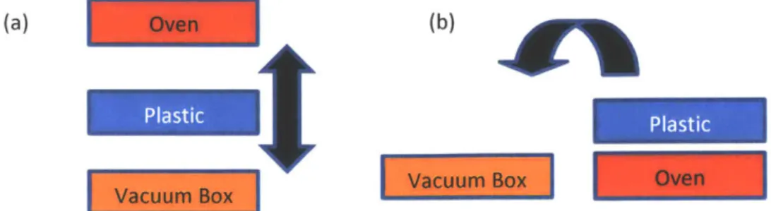
(a) Oven (b)
Plastic Plastic
Vacuum Box Vacuum Box Oven
Figure 4: (a) Preliminary ideas for thermoform design. (a) One design consists of translational motion between the oven and the mold. (b) The other design transports the plastic between the heater and the mold via rotation. The black arrows represent the motion of the plastic between the
oven and vacuum box. Below are the pros and cons of each strategy conceived above: Drape Forming Top to Bottom
* Not much movement involved for plastic * Gravity Assist for the plastic
* General number of parts needed less than other methods
* Draping plastic can lead to deformations in the final plastic part
Drape Forming Rotation
* Depending on the position of the platform with the vacuum, any geometric errors from draping plastic can be minimized
* Potential to be more compact than Top to Bottom Solution
* Initial interaction with soft plastic and mold could cause dimension issues.
In the end, the better method was the top to bottom method since it was simpler to make overall. In addition, the parts that need to be made for proof of concept prototypes are simple, since these
3
MECHANICAL DESIGN
3.1
Overall Design
The final concept adopted as shown in Figure 5
Oven a--Structure Movable Carriage with wooden clamps Vacuum
3.2
Structure
The goal for the structure design was to create one that was low in material cost, easy to fabricate, and also rigid so that it can handle accidental impact forces from the user. Because of this, the majority of the structure is constructed using 1/8" thick pieces of maple hardwood. This hardwood was chosen because of its ease of manufacturing via laser cutting, and its ability to handle high temperatures for short durations (since wood is an insulator). Since the thermoforming process is a short process, the wood will not constantly be in a heated state.
As shown in Figure 6 (a) and (b), the oven section and vacuum box are constructed out of maple plywood, which was laser cut to the required shapes. In order to increase the rigidity of the structure, aluminum 1-brackets were attached between the vacuum box and the oven. Specifically, long 1-brackets attached to wider brackets were used so that these elements add significant structure rigidity. In order hold all parts of the structure together, 8-32 screws were used.
Long I-bracket coupled with wide 1-bracket
Figure 6: Overall frame of the thermoform machine with L-brackets
3.3
Oven
The majority of the work was done on the oven itself since it is the most critical and also the most potentially dangerous to fabricate (due to large heat fluxes). The goal for this oven was to design one that could not only output the desired power but also be built in a way that lowers the users' risk of burning themselves during use. To create an inexpensive oven, 80% nichrome wire alloy was used. Specifically, nichrome wire was chosen because of its chemical stability at high temperatures, commercial availability,
for most hardwoods). After choosing nichrome wire as the heating element, the next step was to determine the overall power requirements needed in order to heat the plastic to glass transition state. The design process for this step is as follow:
Assuming Vwai is 120 Vand assuming nichrome obtains 204 degrees C via 3.6A of current, the required resistance is as follows:
Rwire= Vwall 120 = 33.5 f (1) Inichrome 3.58 A
Given that the Resistance Per Foot of Nichrome = 0.64!
ft
Rwire 33.5n ~ 52feet.(2)
The Length ofNichrome = Resistance Per Foot of Nichrome - 0.64 2
ft
This yields a total oven output: 120V * 3.6A = 432 W
After this calculation, the next part that was done was determining how the nichrome wire would be laid out within the oven. It was determined that the best way to do this was via an Icarus Crossing layout (similar to the way that heating elements are arranged inside toasters). As shown in Figure 7(a) and (b), the heating element is laid across the length of a mica sheet that can sustain high temperatures and then wrapped around the edges of the sheet so that it can be laid across the sheet again but in the opposite direction.
ab
Figure 7: Icarus crossing layout with numbers showing nichrome path Besides the mica sheet, the following elements were included in the oven as well:
* Mineral wool insulation
* Aluminum sheet metal reflectors * Open air space
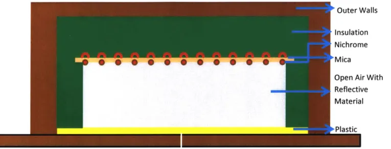
As shown in Figure 8, the air space where the plastic is heated within is directly above the plastic. The aluminum sheet metal is placed on the walls of this air space in order to reflect heat from the nichrome back into the air, thus making the system more efficient. Above the air space is the sheet with the nichrome wire that provides heat to the system. Above this layer is the high temperature mineral wool, which is important for insulating the system and lowering the user's risk of getting burned from the machine. The insulation is placed on all sides of the system and essentially provides a wall between the outer wall of the thermoform and the oven.
Outer Walls
Insulation Nichrome 0 0 0 4 0 0Mica0 0 0
Open Air Wit Reflective Material
Plastic
Figure 8: Cross Section of Oven With Component Directions
In order to model the oven, it was assumed that the heat flux of the system was 1 -D in nature. By doing this, a thermal resistance map can be created for the system so that the power transfer between different parts of the system can be determined. In addition, this thermal resistance map provides the temperature of the structure at different points of the machine, specifically the outer wall temperature. In order to simplify the modeling of this device, the dominance of conduction, convection and radiation was calculated, specifically for the heat transfer between the air and the plastic.
To determine the ratio between convection and conduction within the air space, the Nusselt number was calculated via heat transfer correlations. Assuming that the nichrome wire layout on the mica
sheet is simplified into a flat plate with a uniform heat flux outputting from it, we can compute the Nusselt number for the case of natural convection on a heated horizontal plate facing down. The equation
(LmiC) 0.7 X = 13.5Ra-0.16 + 2.2 (4) (L Nu = 10.4 Where Nu = Nusselt Number
Lnica =Mica Thickness =.0625" 1.59 mm
L Depth of the Oven =4" = 101.6 mm
W Width of the Oven =12" = 304.8mm
Ra = Rayleigh Number =3.2*106
Thus, after performing the calculation, it is determined that Nu = 10.4, which means that
convection is ten times more dominant than conduction in the air space. Because of this dominance, we can make the simplification that conduction inside the air space is sufficiently smaller than convection therefore can be ignored. Therefore, the dominant forms of heat transfer to the plastic are radiation from the nichrome wires and convection from the heated air. Since heat is being transferred downwards from
the nichrome to the plastic, the oven can be modeled using the 1 -D heat flow technique of thermal circuits.
In order to utilize thermal circuits, the thermal resistance of each component in the oven has to be determined. The first step in finding the thermal resistances is to calculate the convective heat transfer coefficient for the air and the radiative heat transfer coefficients for the nichrome and the aluminum sheet metal. The values for these coefficients are given by
hrad nicrome 4oEjTm = 11.65 ' (5) [6]
hrad aluminum 4E 2Tm = 1.8 - (6) 6]
Nu kair W conr L
L
7m
2K
(7)Where
hrad nichrome = air radiative heat transfer coefficient
hrad aluminum = aluminum radiative heat transfer coefficient
hconv = air convective heat transfer coefficeint Nu = Nusselt Number = 10.4
W
kair air thermal conductivity = 0.36
mK
w
e1=Nichrome Emissivity Coeff icient -- 0.7 w [7,]
E2 = Aluminum Emissivity Coefficient - 0.09 W [7]
Tm = Mean Temperature Between Nichrome and Oven Air = 450 K
Given the values above for the radiative and convective heat transfer coefficients, the thermal resistances of each element in the oven can be determined as follows:
1 K Rrad nichromel = = 2.0 - (8) hrad nichrome A1 W 1 K Rrad nichrome2 = = 2.0 - (9) hrad nichromeA1 W Raiuminum sheet3 = = 8.9 6 K (10) haluminumAaluminum W Rc = 1 = 1.54-K (11) hconvAmica W
Rcond mica k mica = 0.006 (12) kmica Amica Linsuiat ion K Rcond insulation - = 0.04 - (13) kinsuiationAinsuiation W Rcond wood ""- = 0.004 K (14) kwoodAwood W Where
A1 = Area of Nichrome Wire Radiating to Plastic = 0.017m
2
Aaiuminum = Area of Aluminum Sheet Metal = 0.06m2
Amica = Area of Mica Sheet = 0.08m2
Ainsulation = Area of Insulation = 0.09m2
Awood = Area of Wood =0.2m2 Lwood= thickness of wood = 0.006m
Linsulation = Length of Insulation = .0381m
w
kmica = thermal conductivity of mica = .71 - [8]
kinsulation = 0.0364 w [9]
mK
kwood = .16 w [8]
mK
Rrad nichromel = Resistance from Nichrome Wire Radiation to Plastic Rrad nichromeZ = Resistance from Nichrome Wire Radiation to Structure
Rcon = - 1 = Resistance from Convection to Oven Air Space
hconvAconv
Rcond mica = Lmica =Resistance within Mica sheet conduction kmica Amica
Rcond insulation - Linsulation - Resistance within insulation conduction
kinsulationAinsulation
Rcond wood ~ Lwoo -= Resistance within wooden structure
kwoodAwood
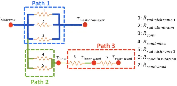
When the thermal resistances have been found, the 1 -D Heat Resistance Map can be constructed, as shown in Figure 9 below:
Tnichrome
I
I
I
I
I
Path
1
2
ITpiastic
top layer3 |
Path
3
i-n----
--- ---Tinnel 6 inner wood 7 Touter wood I
I
---1: Rrad nichrome 1 2: Rrad aluminum3: Rconv
4: Rcond mica5:
Rradnichrome26:
Rcond
insulation 7: Rcond woodPath 2
Figure 9: 1-D Thermal resistance map of oven for thermoforming machine.
Using the concept of series and parallel resistances, the total resistances between the plastic and the structure can be determined as follows:
1 1 1 1 -+-+ -= (15) Rtotal Pathi R1 R2 R3 1 1 1 1 ____= -+-(16) Rtotal Path2 R4 Rs
Rtotal Path2+Path3 = Rtotal Path2 + Rcond insulation + Rcond wood (17)
From these expressions, the division of the heat flux
Q
between the plastic and the structure is determined as follows:Rtotal Path 2
Qplasttc =-- QtotaiPathi = 430
W
* RtotalPath2 + Rtotal Pathi
Qstructure = Qtotal Path2 = 430 W * Rtotal Path 1 = 33 W
(19)
Rtotal Path2 + Rtotal Pathl
In addition to finding the heat flux flowing to the plastic and the structure, the temperature of the outer wall can be determined from the resistance model in Figure 9, given Tnichrome and Qpiastic
Touter wood = Tnichrome - Qpiasttc = 477.15K - 32.4K = 444.7 K = 171C (20)
Rtotai Path 2
Although this temperature is quite high, the wood will be in this heightened temperature state for a relatively short period of time due to how quick the thermoforming process is. Another aspect to
determine is how much time it takes to heat the plastic to the required glass transition temperature. Since polycarbonate sheets have a transition temperature of 150'C, the amount of heat (Q) needed for an individual sheet of this material is as follows:
Q = mcAT = 14459J (21)
Where
m = mass of polycarbonate sheet = 0.089 kg
c = specific heat capacity of polycarbonate = 1200
kg K
AT = Temperature difference between glass transition temperature and ambient = 130*C
Now given that the power flowing to the plastic is 386 W the amount of time needed to heat the plastic is as follows:
t 37.5s (22)
Granted, this time is a lower bound for operation time due to the fact that the nichrome would heat both the plastic and the wooden carriage carrying the plastic. However, this number gives an idea of the operation time's order of magnitude, which is reasonable for a user who needs to quickly prototype plastic parts.
3.4
Vacuum Box
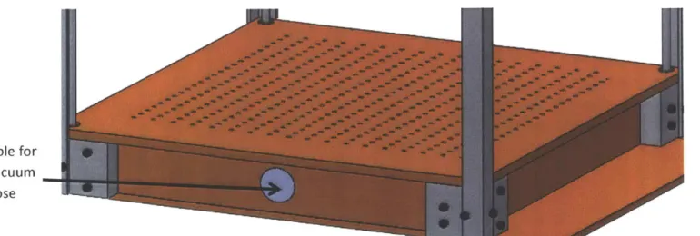
The goal for the vacuum box was to create a source of negative pressure so that the heated plastic can form over the mold effectively. The design that was used is shown in Figure 10: a box with multiple small holes spaced out within a 12" x 12" square area. An array of small holes was used so that the negative pressure can be applied over the entire area instead of a localized area. In addition to this, a 1.25" diameter hole was added to the side of the box so that negative pressure can be supplied via an external vacuum cleaner,
Hole for vacuum hose
Figure 10: Vacuum Box Design With Small Hole Array
The main issue that had to be considered with this design was sealing off air flow into the box, thus decreasing the effectiveness of the negative pressure applied to the plastic. To solve this problem, a caulking sealant was used on the edges where parts of the vacuum box joined together.
3.5
Slider and Carriage
In order to accomplish the top to bottom movement of the plastic, a rod slider system was utilized. To clarify, this slider system consisted of four rods (one on each of the corners of the thermoform
machine) with the purpose of constraining a carriage (with bearings) moving the plastic between the oven and the vacuum.. The concept of using rods was preferred over other methods because it allowed the carriage to only move in a top to bottom fashion (with some angular or translational error due to bearing tolerance). Figure 11 shows the orientation of one of these sliders.
Sleeve bearing on carriage
Figure 11: Slider rod at one corner of thermoforming machine
4, 4P dk 4W do -M *46 Ob ft OW ft 4W .6 AM -0 ow M 1-0 4W a* Am" M a* dim 4t - 4P .41 4b, 41L - -- R Kv - - d1b -W M - - -M db . A* 41& 4% .00 4% -0 M 40 AW 4P 40 &.ft - M '.0-P Ak Idb Ift .46 1 ;0 Ift", go Ow 40 At ..-4LO" 40 0,00 dip W w . d1b - Oft '.A% -0 AW .- 0 - ft dk .40 4P jo dwom - ft ." is al-t 40; -W
3.6
Clamps
The other main concept that we examined was the clamping system and the method of changing plastic sheets. We needed to find a way to clamp down the plastic in a way so that it was properly constrained during the thermoforming process. In addition, we wanted to find a way so that the clamping system could take into account different size sheets of plastic. One of the ideas that were examined, as shown in Figure 12(a), is a c-clamp shaped system
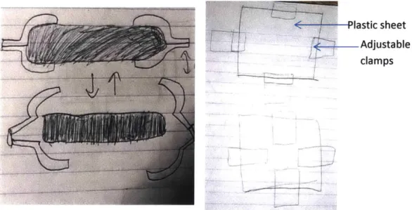
Now many of the concepts involved using a moving clamp platform (Figure 12(b)) of which the user could adjust the position of the clamp positions so that the clamps could hold a 3"x 3" sheet up to a
12" x 12" sheet. While a moving platform would have been a nice way to customize the sheet holder very quickly, the main issue was added complexity as well as issues with ends of the plastic being unclamped due to the positions of the moving clamps. Since these clamps would have to be made to clamp at least a 3" x 3" sheet, it would not be possible to clamp all lengths of the edges if a larger sheet was needed.
lastic sheet Adjustable
clamps
Figure 12: (a) C-clamp idea for holding plastic; (b) Adjustable clamp for different plastic sizes Therefore, instead of making a device that already had an adjustable size clamping system, it was decided that it would be better to go for a more modular approach. To clarify, this means that it would be better to quickly manufacture new clamping plates depending on the size of the plastic being held in the thermoform. By making this part easy to manufacture, the user can quickly customize their clamping plates based on the sizes that he or she has available, so long as certain dimensions of the clamping plate are met. Figure 13 shows the final design for the clamping system.
Wooden Clamps Winged-Nuts -qh F,
/
Z~
do
4
ELECTRICAL DESIGN
4.1
Strategy
The next area of focus is the electrical design of the thermoforming machine. As mentioned in the previous section, the goal was to produce 429 W of power from the heating coils used in the oven via 120 V AC wall power. In order to control this wall power, a TRIAC was used. The operation of a TRIAC is as follows: a zero-crossing AC detection circuit is created using an opto-isolator that separates the mains voltage reference from the microcontroller. Once the microcontroller reads the zero-crossing signal, it initializes an interrupt, which sends a pulse to an opto-coupler input. On the output of the opto-coupler is the TRIAC gate, which receives the signal from the microcontroller, and turns on the TRIAC for every zero-crossing that occurs. The other two terminals of the TRIAC are connected to 120 V and the heating coils, thus making it possible to control the power flowing through the coils. A visual version of this concept is shown in Figure 14.
MTI
G
MT2
a .4 w w 10 - Gate Voltage 8 - Output Voltage 6 -. Input Voltage 2 .4 t3 -6 b-8
-10Figure 14: (a) TRIAC circuit symbol with usual form of component in circuit. (b) TRIAC operation theory. Pulses are sent to the TRIAC at every zero crossing, so that power continually flows to the
load. These pulses can be delayed so that the power delivered is modulated.
150 100 50 -50 2 .100 -150
i
MT1 G4.2
Circuit Layout
After looking into heating circuits online, a control circuit was created. However, the additional aspects include a thermocouple circuit (for measuring the temperature within the thermoform) and a LCD screen circuit (for displaying the temperature). The layout of the components as well as the code used are shown in Figure 15 (a) and (b).
-- Thermocouple
Microcontroller a' 4
-se V6 NVA R I HUT a 3n
Temperature .. , Heater
Display
3Vmatai2I
Outputb #include "avr/interrupt.h" #define triacPulse 5 //#define SW 4 //#define aconLed 12 #define ZERO 3 void setupO { pinMode(3, INPUT);
digitalWrite(3, HIGH); // pull up pinMode(5, OUTPUT);
attachlnterrupt(digitalPinToInterrupt(3), acon, CHANGE); } void loopo{} void acono { digitalWrite(5, HIGH); delayMicroseconds(550);
// delay 550 uSec on output pulse to turn on triac digitalWrite(5, LOW);
}
Figure 15: (a) Circuit layout for heater controller with labeled components; (b) Code utilized for heat control [10]
5
FABRICATION
5.1
Structure
The overall frame for this thermoform (shown in Figure 16) was constructed using .25" maple plywood. The plywood was chosen due to its ability to be quickly manufactured into different shapes (via laser cutting). In addition, the laser cutter has about a .005" error so the parts can be made with a
satisfactory degree of accuracy. Granted, the issue with using wood is the tendency for it to bow, therefore, the wood had to be weighted down in order to keep the high accuracy of the parts. In addition to cutting out the wooden frame, the mica sheet (.016" thickness) was cut out via a laser cutter, although
Figure 16: (a) straightening plywood for laser cutter manufacturing; (b) laser cutting of vacuum box top with weights that were used to straighten the wood; (c) laser cutting of oven wall section without weights; (d) laser cutting of mica sheet, which was possible due to
the edges of the sheet showed signs of charred remains, which means a decrease in accuracy. However, the accuracy of the placement of the nichrome wire on the mica sheet was not a significant factor since all of the heat flux would be used to heat the inside air and plastic.
The next main aspect of manufacturing the structure was machining the aluminum components, specifically the long and wide L-brackets. For the wide L-brackets, they were constructed using a 2" x 2" x 24" stock of aluminum that was milled into the desired L-shape and thickness (.75" thickness). After this, the necessary holes for the brackets were drilled into the material so that multiple smaller L-brackets can be cut with a horizontal band saw after all of the necessary holes were created. Figure 17 shows some of the important manufacturing processes.
Figure 17: (a) holes drilled for 1-bracket bar, which allowed for multiple I-brackets to be formed as shown in figures (b) and (c). After this machining, the brackets were cut out using a horizontal
band saw, but the machine's low accuracy varied the heights of the I-brackets. After the machining was done, the wooden parts and L-brackets were assembled together (as shown in Figure 18).
Figure 18: (a) connection between longer L-brackets and wider ones via 8-32 screws. This pattern was used in order to create the overall structure (as shown in (b)).
5.2
Oven
For oven construction, the nichrome wire was cut to the desired length and wrapped in a coil fashion, instead of keeping it straight as previously planned. By doing this, the chance of shorting the nichrome with each other is decreased. Once the wire was shaped into a coil, it was laid onto the mica sheet and held at the ends of the sheet using bolts and washers. Once this was created, the sheet was inserted into slots at the top of the oven and fastened using epoxy. After the mica sheet was inserted, the inner sides of the oven frame were lined with the mineral wool using a spray on adhesive to fasten the wool. The same process was used in order to fasten the reflective sheet metal to the mineral wool. Figure 19 (a) and (b) show the outer casing of the oven and the layout of the nichrome wire.
Figure 19: (a) Oven box outer casing and (b) nichrome wire layout on mica sheet (note that the sheet metal has been taken off in order to show all sides of the insulation clearly).
5.3
Vacuum Box
Since the vacuum box was part of the structure design, it was made out of 1/8" laser cut maple wood. The most important addition that was needed for the vacuum box was a caulking sealant for the edges of the box (so that a stronger vacuum could be created). The caulking that was used was a silicone based material which was applied to all open corners and sides of the vacuum box.
5.4
Slider and Carriage
When the structure was completed, the next step to the building process was installing the axial sliders. As part of the design, the axial sliders were inserted into a 3/8" diameter hole on the top area of the L-brackets (as shown in Figure 20). Once they were inserted into this hole, set screw was used in order to hold the axle from the top and bottom. Originally, the size of these set screws were supposed to be 8-32, but due to a machining error, the sizes had to be enlarged to an M6, which was more
advantageous since it allowed for a larger surface area to hold the axles in place.
L<IM,
Figure 20: Thermoform with 4 slider axles installed. These axles were held into place using an M6 set screw and lubricated with lithium grease for decreasing friction. As a note, the L-brackets were
5.5
Clamps
For the clamping system, the way that it was fabricated was via laser cutting. Specifically, 1/8" thick wood was used to cut out the clamps themselves. In order to constrain the clamps to the carriage, threaded wood inserts with a 1" threaded rod were screwed into the carriage carrying the plastic. By doing this, the T-nuts can be screwed onto the threaded rod and provide the clamping force for the system. The physical shape of the design is shown in Figure 21.
- - I Al " 'd
:
wl
6
TESTING
6.1
Objective
In order to test how effective this thermoform design was, a sample mold was obtained and used for thermoforming. There were two goals for the testing phase: to confirm if the plastic parts were within the .05" tolerance range and to compare two types of thermoform processes. To clarify on the second goal, the two processes that were explored were thermoforming once the air reaches 150'C and
thermoforming once the plastic reaches 150*C. The question to be answered is whether or not there is a statistically significant difference in the molded parts created by these two processes. By examining this, the user can understand the tradeoffs in part quality and time when comparing both processes.
6.2
Procedure
In order to obtain the goals stated above, a sample rectangular aluminum mold (as shown in Figure 22) was used to make plastic parts. In order to make sure that the piece was adequate for
thermoforming, all the faces were machined to flat surfaces and all the edges and corners were rounded. After these processes, the mold had final dimensions of 1.986" x .826" x .906"
Figure 22: Aluminum Mold Used for Testing
After machining the mold, the following procedure was used to compare the two thermoforming processes:
Heating Air Temperature to 150'C
1. Thermoform a 6" x 6" sheet by placing the sheet in the carriage and moving it to the oven chamber until the oven air temperature reaches 150'C on a thermocouple.
2. Remove the carriage from the oven and place it on top of the vacuum box so that a vacuum is applied to the bottom of the sheet until the part cools to room temperature.
3. Repeat this process for three more sheets for a total of four molded parts.
Heating Plastic Temperature to 150*C
1. Thermoform a 6" x 6" sheet by placing the sheet in the carriage and moving it to the oven chamber until the plastic temperature reaches 150'C (determine this temperature via infrared laser gun.
2. Remove the carriage from the oven and place it on top of the vacuum box so that a vacuum is applied to the bottom of the sheet until the part cools to room temperature.
3. Repeat this process for three more sheets for a total of four molded parts.
Measurement and Data Analysis
1. Measure the length of each vertex on each plastic part using calipers.
2. Record the dimension of each vertex and whether or not that measurement second process.
3. After obtaining these dimensions, perform a t-test to determine the statistical processes.
was for the first or
significance of both
Figure 23 (a) and (b) shows the tools that were used in order to perform this testing process including the infrared laser gun and the thermocouple.
- lna'el Se=7'
umainm Vrat r Control Circuit
nocouple Thermoform Machine
Figure 23: Thermoform Machine With Testing Devices (note that the rods were removed temporarily).
6.3
Analysis
With regards to the parts created and the conclusions that can be made, one important observation to note is the incomplete forming of the plastic part onto the mold (as shown in Figure 24 (a) and (b)). Because of this, the parts created from the thermoform machine only have the top dimensions of the mold fully formed instead of all sides of the mold. The possible cause behind this is that the vacuum box is not providing enough negative pressure on the plastic part. In order to improve the vacuum box, the edges have to be sealed even tighter or a vacuum with a stronger negative pressure must be used. Regardless, the top face of the mold was consistently formed on each plastic test piece; therefore, the dimensions from this face were used in the analysis.
(a) - I(b)
i
...
...
Figure 24: (a) Output Parts from Thermoform Machine With Top Forming; (b) Surface dimensions taken for data
After measuring each of the part dimensions for each process, the mean of the dimensions for each process was calculated. For the 150*C air process, the mean length was 1.486", and for the 1500 plastic process, the mean length was 1.477". Once this was complete, a one tailed T-test was performed
on the data assuming that the null hypothesis used for this test states that there is no difference in the part dimensions created by either two processes. In addition, the a-level (the significance level) was set to 0.05. In the end, a value of .482 or 48.2% was obtained from the T-test. Since this probability is higher than the significance level, this means that the null hypothesis cannot be rejected. Because of this, it can be concluded with 95% confidence, that the difference in the part dimensions created by the two
thermoforming processes is insignificant.
In addition, the mean difference in dimension for both processes was higher than the desired tolerance level. Specifically, for the 150 *C air temperature process, the mean dimensional difference was
.0800". As for the 150* C plastic temperature process, the mean dimensional difference was .0711". Therefore, the current state of this machine does not reach the desired tolerance range of +0.05 as stated in the functional requirements.
6.4
Conclusion
In conclusion, the t-test shows that there is no significant difference between the dimensions created by the two processes. Thus, if the user were to heat the plastic to 150*C or the air to 150*C, then there would be no difference in the quality of the parts created by both processes. As a note about this conclusion: some source of error may be attributed to the plastic not fully forming on the mold, due to the
3
fully thermoformed part from it. However, it seems that either one of these processes will produce plastic parts of similar dimensions.
Also, this machine does not create parts within the desired tolerance range of 0.05" given the two thermoforming processes tested on this machine. The reason behind this is most likely because of the vacuum box and its design, specifically, its ability to create an effective negative pressure to form the plastic effectively.
7
FUTURE WORK
7.1 Further Modifications
Although this device was able to thermoform plastic parts, it was not able to thermoform these parts fully. As mentioned previously, the vacuum creating negative pressure was not strong enough to
form the plastic around the mold. One way to solve this issue would be to add a rubber sealant at the bottom of the carriage. Essentially, this sealant would allow the user to deform the rubber and seal the area underneath the plastic better so that air does not leak into that area. The other improvement that could make the vacuuming process better is raising the mold via a half inch spacer with holes for applying the negative pressure. By doing this, the plastic would be able to drape over the mold better instead of having an air space in between the plastic and the vacuum box, which impedes the forming process (as
shown in Figure 25). Future development of this device would try to include some of these changes into the machine.
Carriage with Plastic
>Axles
Raised Platforms
> Top of Vacuum Box
Aluminum Mold
REFERENCES
[1] "The Principle of Thermoforming," Extruders ofplastic sheet andfilm, 15-Mar-2016..
[2] "FJL-400A Automatic Plastic Lid Thermoforming Machine -Plastic Cup Thermoforming Machine -Zhejiang Fuxinlong Machinery Co.,Ltd." [Online]. Available:
http://www.plasticcupmachine.com/productshow/15.html. [Accessed: 26-May-2017].
[3] "Centroform EZFORM LV 1827 11 OV Tabletop Vacuum Forming Machine." [Online]. Available: http://www.robotshop.com/en/centroform-ezform-tabletop-vacuum-forming-machine.html.
[Accessed: 31-Mar-2017].
[4] "ProForm Vacuum Former (I IOV)
I
SKU: 7017020." [Online]. Available:http://www.practicon.com/item/proform-vacuum-former-1 1 Ov-7017020/7017020. [Accessed: 24-May-2017].
[5] "Formulas, Conversions & Calculations Pelican Wire," 20-Sep-2012. [Online]. Available:
https://web.archive.org/web/20120920075813/http://www.pelicanwire.com/category/formulas-resistance/. [Accessed: 26-May-2017].
[6] "Radiative heat transfer coefficient." [Online]. Available:
http://www.biberthermal.com/ReferenceLinks/ThermalDesignInfo/Radiativeheattransfercoeff i/radiativeheattransfercoeffi.html. [Accessed: 28-May-2017].
[7] "Emissivity Coefficients of some common Materials." [Online]. Available:
http://www.engineeringtoolbox.com/emissivity-coefficients-d_447.html. [Accessed: 28-May-2017]. [8] "Thermal Conductivity of common Materials and Gases." [Online]. Available:
http://www.engineeringtoolbox.com/thermal-conductivity-d_429.html. [Accessed: 28-May-2017]. [9] "McMaster-Carr." [Online]. Available: https://www.mcmaster.com/. [Accessed: 28-May-2017]. [10]"Arduino Playground -ACPhaseControl." [Online]. Available:
![Figure 2: Thermoforming Machine for Mass Production[2]](https://thumb-eu.123doks.com/thumbv2/123doknet/14680599.559176/10.917.116.788.129.352/figure-thermoforming-machine-mass-production.webp)