Diffraction and Exposure Characteristics of the
Edgelit Hologram
by
Michele Marie Henrion
B.A. (Honors), Holography: the Physics and the Art Brown University
Providence, Rhode Island
1990
Submitted to the Program in Media Arts and Sciences, School of Architecture and Planning,
in partial fulfillment of the requirements for the degree of
Master of Science in Media Arts and Sciences
at theMassachusetts Institute of Technology
September 1995
@1995 Massachusetts Institute of Technology All Rights Reserved
Signature of Author
Certified by
Accepted by
Pr gram in Media Arts and Sciences
June 12, 1995
Vr Stephen A. Benton
Allen Professor of Media Arts and Sciences Thesis Supervisor
4
41
q 'V J-'/VStephen A. Benton Chairperson Departmental Committee on Graduate Students Program in Media Arts and Sciences
;AGSACHUSE TTS
INST
ITUTEOF TECHNOLOGY
OCT 2
6
1995
Diffraction and Exposure Characteristics
of the Edgelit Hologram
by
Michele Marie Henrion
Submitted to the Program in Media Arts and Sciences, School of Architecture and Planning, June 12, 1995, in partial fulfillment of the requirements of the degree of
Master of Science in Media Arts and Sciences at the Massachusetts Institute of Technology
Abstract
The edgelit hologram overcomes the exacting lighting requirements of con-ventional holograms, making possible a compact, portable, high-quality, three-dimensional display that can be viewed under diverse lighting conditions. The production of successful edgelit displays requires an understanding of the dif-ferences between edgelit and conventional holograms. To this end, this thesis characterizes the significant differences in fringe structure, diffraction efficiency, chromatic behavior, and the calculation of exposure energy.
Thesis Supervisor: Stephen A. Benton Title: Allen Professor of Media Technology
This research was supported in part by Honda Research and Development Co., Ltd.; NEC Corporation; and International Business Machines, Corp..
Diffraction and Exposure Characteristics of the
Edgelit Hologram
by
Michele Marie Henrion
Thesis Readers
Approved by Hendrik J. Gerritsen Professor of Physics Brown University Approved by/
V
Paul M. Hubel Research Scientist Hewlett-PackardMy brother Tim, in a very strange, roundabout
way, put me back on this path; so I dedicate this thesis to his memory.
Acknowledgements
Many people have contributed to this project through their help to and support of me. I am grateful to have the opportunity to thank them here.
My parents: where, quite literally, would I be without them; particular
thanks for their financial support of, their tolerance of, and their pride in my academic endeavors.
Stephen A. Benton: for accepting me into his group of elite holographers; for teaching me more about holography than I ever would have thought possible; and for advising me throughout this project.
Hendrik J. Gerritsen: for his loving support of me at Brown and since, in life, holography, and physics; for agreeing to be my advisor at Brown; and for his careful reading of this thesis and many insightful comments.
Paul M. Hubel: for warmth and kindness, especially during the time we overlapped at MIT; for reading this thesis and for the excellent comments par-ticularly in the Chromatic behavior chapter.
Michael Halle: for incredible amounts of assistance, innumerable helpful dis-cussions, the stellar thesis example; and for altering his excellent vertical-focus raytracing program to accommodate the edgelit hologram's special computation
considerations.
Michael Klug: for helping me get familiar with the labs and techniques of the Spatial Imaging Group, for useful comments on the edgelit hologram, and for running the test that showed that a block-recording geometry with an absorber can produce an edgelit hologram with minimal woodgrain if the index of refraction of the coupling fluid perfectly matches the index of glass.
Sean Nolan: for the highest quality assistance in the lab, excellent help in ironing out the problems of the early exposure experiments, and painstaking care and attention to detail in the exposure of and density readings of hundreds of test plates.
Jack Miller: for top-notch lab assistance during the setup and exposure of the three-color rainbow edgelit hologram; for acting as my hands, idraw wizard, artist, clarification consultant, and last-minute-panic savior in the production of the majority of the lovely figures in this thesis (thanks, too, for loaning the Happy Meal pig!); for music, skamit, and straight edge, too.
Ali Azarbayejani: for teaching me the basics of how to write a thesis, for providing excellent feedback after looking over one of the first drafts, for gen-erous assistance with Mathematica and Latex; for giving me invaluable lessons on how to work, run, and the importance of breaks; and for sweeping in, in the final twenty-four hours, making the completion of the document a possiblity
and then a reality.
The Advanced Human Interface Group at the MIT Media Lab: for loaning me the Dragon Dictate voice recognition hardware and software that I used to write this thesis.
The Access Technology for Information and Computing (ATIC) Lab at MIT: for existing.
Dr. David Diamond and Michael Erard: for helping with the healing of my injured hands.
Carol Burns and Patty McGill: for superb occupational and physical therapy-you both helped me in ways well beyond simple physical rehabilitation.
Linda Peterson and Santina Tonelli: for making the administrative side of the lab so easy to navigate and so personable.
Melissa Yoon: for making all those appointments, changing all those ap-pointments, answering questions, providing keys, helping with faxes and Fed Ex's, and, most of all, for being so good-natured and friendly.
Don Thornton: for teaching me so much lab holography, and encouraging me to head off, on my own, to my first holography conference back in January of 1989.
Bill Farmer: for giving me the inside scoop, sending me your lab notes on the edgelit hologram from Japan, and warning that it would be hard.
Sunny Bains: for the first full read of the thesis, lots of moral support and the Poynting vector.
Arno Klein: for meticulous proofreading.
Alison Henrion: for deciding to move in with me just in time to provide much needed and appreciated chauffeur services, food delivery, and a calm clear-headed presence.
Wendy Plesniak: for being there throughout, encouragement, office space, and that joyous look at the xdvi.
Pierre St. Hilaire: for your example and warmth-I really admire you. Mark Lucente: for thought-provoking discussions and help with EE theory. Sabrina Birner and Mary Lou Jepsen: for going to MIT first and for many helpful validating talks.
David Pitcher: for help designing a sleek, compact edgelit display; for helping make my final holography show at Brown the success that it was; and for being my most awesome partner in holography dreaming.
Amy Connor: for being the thesis buddy who turned into a best friend. Lis Drake: for giving me a place to live when I really needed it, and for so much love and support.
Victoria Byerly: for your example, friendship, and support-for finishing your Ph. D. and getting a great job in your dream city.
Sharon Krause: for being my #1 calming influence.
Debbie Armstrong: for help with keeping the focus and managing it all. Andy Hong: for skate breaks, sanity checks, snowboarding, talks, music, and goofing around.
Marty Friedmann: for shy, silly distractions-I miss you.
Rodney Mullen: you remind me of my old self, of how I used to learn this kind of stuff just for the fun of it-thank-you for reminding me.
Anne Welch: for that excellent book on writing and many other good writing ideas.
All my wonderful friends: for support, help, and offers of help.
Mrs. Swain: your influence has been the primary undercurrent of my life-you taught me a joy and fun in figuring out problems that has sustained me through much of my life, and, even in hard times, when I feared I may have lost that joy and fun forever, I have never stopped longing for it. Mira! It reawakens!
Contents
1 Introduction 2 Background
2.1 The edgelit hologram . . . . 2.2 Holograms closely related to the edgelit .
2.2.1 TIR holograms... 2.2.2 Waveguide holograms (WGH's) . .
2.2.3 Evanescent wave holograms . . . .
3 Fringe structure and diffraction efficiency 3.1 Fringe structure . . . . 3.1.1 Theory . . . . 3.1.2 Conventional holograms . . . . 3.1.3 Edgelit holograms . . . . 3.2 Diffraction efficiency . . . . 4 Chromatic behavior 4.1 Bandwidth ... 4.2 Angular dispersion 4.3 Location of vertically 4.4 Image appearance 4.4.1 Large master 4.4.2 Rainbow . . . 4.4.3 Small master
focused image points
. . . . . . . . . . . . . . . 5 Exposure energy
5.1 Introduction ...
5.2 Models for effective exposure energy (EEE) 5.2.1 Hypothesis a . . . .. 5.2.2 Hypothesis . . . .. 5.2.3 Summary . . . ..
5.4 Comparing EEE models with experimental data . . . 5.4.1 EEE - EDR: in-air geometry . . . . 5.4.2 EEE - EDR: tank geometry . . . .
5.5 Results and discussion... . . . .. 6 Conclusion 6.1 In sum m ary . . . . 6.2 Future work . . . . A Derivation of equations A .1 Phase .... . . . . A.2 Interference... . . . . A.3 Diffraction... . . . . . . . ... B Labeling conventions B.1 Beam angle . . . . B.2 Polarization . . . .
C Geometry-dependent functions for EDR calculation D Reflections D.1 The basics . . . . D.2 Conventional holograms . . D.3 Edgelit holograms . . . . . E Edgelit raytracing . . . 75 98 98 100 101 104 104 105 106 114 . . . . . . . . . . . .
List of Figures
1.1 An edgelit hologram . . . . 15
1.2 The display geometry of a conventional transmission hologram. . 16 1.3 The display geometry of a conventional reflection hologram. . . . 17
1.4 The display geometry of an edgelit hologram. . . . . 17
2.1 A total internal reflection (TIR) hologram and one type of reflec-tion edgelit hologram . . . . 24 2.2 Light ray path down an optical waveguide . . . . 25 2.3 Waveguide modes evident in the highly magnified ends of fibers
(from Hecht). . . . . 26
2.4 Waveguide modes (after Hecht). . . . . 27 3.1 A typical transmission hologram and its beam angles at recording. 32 3.2 Fringe structure of a typical transmission hologram. . . . . 32 3.3 A typical reflection hologram and its beam angles at recording. . 33
3.4 Fringe structure of a typical reflection hologram. . . . . 34
3.5 Schematic of a typical referencing geometry for a tank-recorded edgelit: a holographic plate (glass and emulsion) is immersed a liquid having an index of refraction similar to the indices of glass
and em ulsion. . . . . 35 3.6 Schematic of a typical referencing geometry for a block-recorded
edgelit: a holographic plate (glass and emulsion) is coupled to a glass block with a fluid having an index of refraction similar to the indices of glass and emulsion... . . . . . . 36 3.7 Fringe structure of a tank-recorded transmission edgelit. . . . . . 38 3.8 Fringe structure of a tank-recorded reflection edgelit.. . ... 39 3.9 Schematic of a typical edgelit block-recording geometry using an
absorber: a holographic plate (glass and emulsion) is coupled to the glass block and then an absorber is coupled to the holographic plate. ... .... ... .. ...-.-... 40
3.10 Fringe structure of a block-recorded transmission edgelit . . . . . 42 3.11 Fringe structure of a block-recorded reflection edgelit . . . . 43
3.12 Diffraction efficiency il1 versus reconstruction angle 0' for 0% shrinkage. (a) s-polarization, (b) p-polarization (from Elibets et al.). . . . . 46 3.13 Diffraction efficiency i1 versus reconstruction angle 0' for 1%
shrinkage. (a) s-polarization, (b) p-polarization (from Ehbets et al.). . . . . 4 7 3.14 Diffraction efficiency r1i versus reconstruction angle 0' for 1%
swelling. (a) s-polarization, (b) p-polarization (from Ehbets et al.).. . . . . . . . . 48
3.15 Diffraction efficiency 71 versus reconstruction angle 0' for 1%
swelling. Optimized transmission grating. (a) s-polarization, (b) p-polarization (from Ehbets et al.)... . . . . . ... 49 4.1 Wavelength change AA after which no diffracted wave appears
when reconstruction angle is held constant (after Leith et al.). . . 51
4.2 Location of the chromatic output of a hologram illuminated with
diverging white light (after Ward et al. ). . . . . 54
4.3 The wavelength-dependent vertically focused loci of a point constructed by a conventional transmission or a conventional re-flection hologram. Points along the line marked with wavelengths are reconstructed by the center of the hologram. Bars extending out from those points represent the points output by other por-tions of the hologram. The reference source is located 106 mm from the hologram and has an intra-emulsion angle of 25.70 (450 in air). An identically positioned source illuminates the holo-gram. The axes are marked in millimeters . . . . 56
4.4 The wavelength-dependent vertically focused loci of a point re-constructed by an edgelit transmission or an edgelit reflection hologram. Points along the line marked with wavelengths are re-constructed by the center of the hologram. Bars extending out from those points represent the points output by other portions of the hologram. The reference source is located 106 mm from the hologram and has an intra-emulsion angle of 64.70. An iden-tically positioned source illuminates the hologram. The axes are marked in millimeters... . . . . . . . . 57
4.5 Comparison of an edgelit transmission hologram's experimentally-determined (the ragged curve on the left) and theoretically-experimentally-determined (the smooth curve on the right), wavelength-dependent, vertically focused output loci. Points along the theoretically-determined line marked with laser wavelengths are reconstructed by the cen-ter of the hologram. Bars extending out from those points rep-resent the points theoretically output by other portions of the hologram. The reference source is located 106 mm from the holo-gram and has an intra-emulsion angle of 650. An identically po-sitioned source illuminates the hologram. The axes are marked in m illim eters . . . . 59
4.6 A conventional hologram recorded from a large master hologram. 62
4.7 An edgelit hologram recorded from a large master hologram. . . 62
4.8 A conventional rainbow hologram . . . . 63
4.9 An edgelit rainbow hologram . . . . 64 4.10 A conventional hologram recorded from a small master hologram. 65 4.11 An edgelit hologram recorded from a small master hologram. . . 65 5.1 A representation of the a-case for two different exposures,
show-ing the exposshow-ing beams in the emulsion for each case. The cross-sections perpendicular to the beam's direction of travel represent
a unit area... . . . . . . . . 70 5.2 A representation of the a-case for two different exposures,
schemat-ically showing how the emulsion is filled by the exposing light. 71 5.3 A representation of the 3-case for two different exposures,
show-ing the exposshow-ing beams in the emulsion for each case. The cross-sections shown are parallel to the emulsion interface. . . . . 72
5.4 A representation of the 3-case for two different exposures, schemat-ically showing how the emulsion is filled by the exposing light. 73 5.5 The beams present for two different angles in an in-air geometry. 77 5.6 Theoretical and experimental equal density exposure ratios for
s-polarized light plotted against the intra-emulsion angle of the "Exposure I" beam incident on the emulsion from air. The angles shown correspond to angles in air from 450 to 75*. . . . . 78
5.7 Theoretical and experimental equal density exposure ratios for
p-polarized light plotted against the intra-emulsion angle of the "Exposure I" beam incident on the emulsion from air. The angles shown correspond to angles in air from 45* to 750. . . . . 79
5.8 Angle(s) of the reference beam in the edgelit tank for Exposure I. 80
5.9 The 0* beam in the edgelit tank for Exposure II. . . . . 81 5.10 Theoretical and experimental equal density exposure ratios for
s-polarized light plotted against the intra-emulsion angle of the "Exposure I" beam, which was incident on the emulsion from a tank of xylene. . . . . 84
5.11 Theoretical and experimental equal density exposure ratios for
p-polarized light plotted against the intra-emulsion angle of the "Exposure I" beam, which was incident on the emulsion from a tank of xylene. . . . . 85 5.12 Some of the back reflections present during the exposure of a
holographic emulsion with a steeply angled beam . . . . 86 A.1 A spherical wave incident on a holographic emulsion.. . ... 93 A.2 Interference... . . . . . . . 95
B. 1 Angle labeling convention for use in calculations.. . . . ... 99
B.2 Polarization... . . . . ... 100 C.1 Light incident on the interface between two media (after Hecht). 102
D.1 The reflectances of the interfaces of a holographic plate in air. . . 105 D.2 The reflectances of the interfaces of a holographic plate coupled
to absorbing glass with xylene... . . . . . . . 106 D.3 The reflectances of the interfaces of a holographic plate referenced
at 80 degrees in air. . . . 107 D.4 The reflectances of the interfaces of a holographic plate referenced
at 700 in air.... . . . . . . . 107 D.5 Reflectances of the interfaces of a tank-recorded edgelit with
emulsion facing the reference beam . . . 108
D.6 Reflectances of the interfaces of the interfaces for a tank-recorded
edgelit with emulsion facing away from the reference beam. . . . 109 D.7 Reflectances of the interfaces of the interfaces for a block-recorded
edgelit with emulsion facing away from the reference beam. . . . 109 D.8 Reflectances of the interfaces of the interfaces for a block-recorded
edgelit with emulsion facing the reference beam. . . . 110 D.9 Reflectances of the interfaces of a block-recorded edgelit with
emulsion facing away from the reference beam and with black glass. . . . .111
D.10 Reflectances of the interfaces of a block-recorded edgelit with
emulsion facing the reference beam and with black glass. . . . 112
D.11 Reflectances of the interfaces of a block-recorded edgelit with
emulsion facing a 70* reference beam. . . . 113 E.1 Rays incident on the holographic emulsion during recording . . . 115
E.2 Illumination and output rays at reconstruction . . . ... 115
E.3 In the vertical direction, a steeply angled diverging source
ap-proximates a collimated source for a small hologram. This fact is evidenced experimentally by the fact that an undiverged laser beam illuminates the entire vertical extent of a 102 x 127 mm (4 x 5 in) holographic plate when incident at a typical edgelit recording and illumination angle... . . . . . . . . 116
Chapter 1
Introduction
WIl
O
Figure 1.1: An edgelit hologram
Holography has long promised the world glorious, floating, three-dimensional billboard images, textbook figures, cinema posters, artificial environments, fam-ily snapshots, and magazine contents. The public already believes holography to be capable of these feats, and much more; so powerfully does holography's potential spark imaginations and dreams.
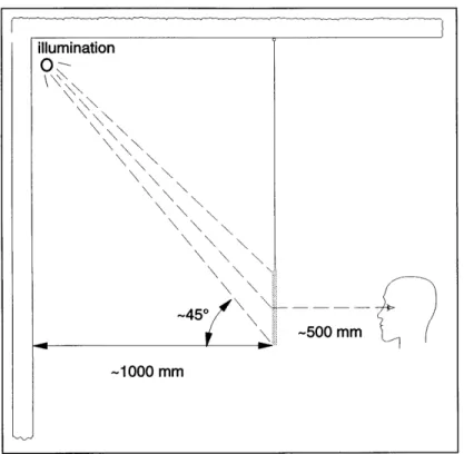
So why do these magical images not surround us? One of the major imped-iments to having high quality, three-dimensional holographic images enter our day-to-day world has been their exacting lighting requirements. Conventional transmission and reflection holographic displays require specialized lighting pre-cisely positioned. They further require that no other light strikes the hologram. Improper light type or location causes the image to appear out of focus or dim;
Figure 1.2: The display geometry of a conventional transmission hologram.
light from multiple sources creates multiple, overlapping images; and an obstruc-tion to the light (someone's head, for example) causes the image to disappear completely. These restrictions result in the fixed, space-consuming, sensitive dis-play configurations characteristic of current, high-quality holographic disdis-plays (see Figures 1.2 and 1.3).
The edgelit hologram, still a relatively new development, overcomes these difficult lighting requirements. As its name implies, the edgelit hologram recon-structs its image by a light positioned at the hologram's edge. The light be-comes an integral part of a compact, self-illuminating display (see Figure 1.4). Experimentation to date indicates that the edgelit hologram is a promising display medium. Further development is likely to ensure that high-quality holo-graphic images will no longer be seen only in darkened galleries where carefully placed halogen bulbs hang one meter from, and forty-five degrees to, each holo-gram.
Common environments like rooms with fluorescent lights, frosted lights, or multiple lights will no longer frustrate the holographic display of three-dimensional information. Architects, engineers, and designers will be able to carry full-color, three-dimensional images of their work in their briefcases. Train stations, hotels, and wilderness outposts will display three-dimensional maps and signs. Chemistry and math teachers will bring edgelit holograms of
com-illumination
0
~45*
-500 mm
Figure 1.3: The display geometry of a conventional reflection hologram.
Figure 1.4: The display geometry of an edgelit hologram.
-1000 mm illumination 450 -500 mm
-500
mm illuminationplex, three-dimensional structures into their class rooms. Surgeons will carry edgelit holograms of three-dimensional magnetic resonance data into conferences with other doctors and with patients. The edgelit hologram has the promise to make holography's many display applications become far more practicable.
Before we can make displays of exceptional quality, we need to understand the unique characteristics of the edgelit hologram. The edgelit has significant differences from conventional holograms in terms of fringe structure, diffraction efficiency, chromatic behavior, and methods for calculating exposure energy.
Most edgelit holograms have a complex, multiple fringe structure which can result in either a lowered overall diffraction efficiency or, for laser-illuminated edgelit holograms, an undesirable, rapid variation of diffraction efficiency with reconstruction angle. Choice of recording geometry, grating optimization, and emulsion processing can eliminate or reduce these effects.
The fringe angle and spacing of the edgelit hologram result in a chromatic bandwidth which lies on a continuum between the bandwidths of conventional transmission and reflection holograms, determining the conditions under which the edgelit is suitable for full-color imaging. The edgelit hologram's high spatial frequency (more than twice that of a conventional transmission or reflection hologram) causes high angular dispersion as a function of wavelength which can act as an asset or liability depending on the imaging configuration and appli-cation. The bandwidth-dependent output locations for points reconstructed by an edgelit hologram differ significantly from those of conventional holograms, additionally changing the rules for full-color imaging.
Another significant difference between edgelit and conventional holograms is in the calculation of exposure energy. In conventional holography, incident exposure energy is usually specified as the incident irradiance multiplied by the time of exposure; in edgelit holography, however, this approximation does not apply, and the time averaged magnitude of the perpendicular (to the emulsion interface) component of the Poynting vector must be multiplied by the time instead.
After defining terminology, reviewing previous work, and clarifying the rela-tionship between the edgelit and other holograms closely related to the edgelit, the thesis discusses the above differences with conventional holograms in depth, using both theoretical and experimental approaches to provide a basis for fur-ther work.
Chapter 2
Background
2.1
The edgelit hologram
Before reviewing the history of technical development in the field of edgelit holography, a few comments on terminology are in order. Numerous terms have been used to refer to edgelit holograms, often creating confusion and poor circulation of information in the field. Since the most commonly used terms have been "edge-illuminated" and "edge-lit", written both with and without hyphens, holograms in this category are defined in this thesis by the term edgelit, which is the natural evolution of the term in accordance with proper English usage [47, 15].1
In the following review of previous work, note that the hologram size and the thickness of the reconstruction block tend to scale together. A thinner recon-struction block results in more reflections of the reconrecon-struction source which, in turn, leaves a smaller surface over which the reconstruction beam from a single reflection can be coupled into the hologram; therefore, in the research to date, a thinner block usually means a smaller hologram.
In some ways, the history of the edgelit hologram begins in 1966 with Leith et al.'s experimental and theoretical analysis of transmission and reflection holo-grams in thick media [27]. In this work, Leith et al. showed that transmission and reflection holograms are simply two opposite ends of a continuum. Al-though the edgelit hologram did not exist per se, Leith et al.'s analysis applies to the edgelit's sensitivity to reconstruction angle, bandwidth, and polarization effects.
'From Strunk and White's The Elements of Style [47]:
Do not use a hyphen between words that can better be written as one word: water-fowl, waterfowl. Your common sense will aid you in the decision, but a dictionary is more reliable. The steady evolution of the language seems to favor union: two words eventually become one, usually after a period of hyphenation.
The history of the edgelit hologram officially begins with Lin's "edge illu-minated" hologram [28]. In 1970, at the spring meeting of the Optical Society of America, Lin spoke of his attempts to make a hologram by introducing the reference beam into the edge of the glass substrate of a holographic plate. Prob-lems caused by multiple reflections and lack of funding caused Lin to abandon the work [6].
For seventeen years, from 1970 to 1987, there appears to have been no fur-ther work published on the edgelit. In 1987, Upatnieks received patents on both a method and an apparatus for recording and displaying "edge-illuminated" holograms [52] and on a "compact" head-up display [51]. In 1988, Upatnieks published a paper describing the work in the head-up display patent [53]. Up-atnieks was able to record successful laser-illuminated edgelits by coupling the holographic emulsion to a "cover plate," i. e., a block of glass.
Upatnieks noted the feasibility of illuminating the edgelit hologram with multiple reflections of the illuminating light in the glass slab. In his record-ing geometry, however, like in other successful geometries, the reference light does not undergo multiple reflections [52]. Upatnieks diagramed the record-ing of a three-dimensional object, but did not mention whether or not such a hologram was successfully recorded [52]. He did, however, show a successful laser-illuminated 102 x 127 mm (4 x 5 in) hologram of a two-dimensional image located at infinity [53]. Though he did not specify it in the text, from the pho-tograph the hologram appears to be mounted on a glass block approximately 20mm (0.79in) thick. Upatnieks also discussed the use of pairs of edgelit gratings for dispersion compensation and the relay of two-dimensional CRT images. The relay function of the gratings closely mimics the function of grating couplers for integrated optics. Upatnieks did not reference Lin's "edge-illuminated" work, although he did reference Nassenstein's evanescent holography work [31, 32] and St. Leger Searle's work in which a glass plate guided light which was later
coupled out with a grating [45].
Shortly after Upatnieks's work, Birner and Benton, of the Spatial Imaging Group at MIT's Media Lab, produced the first white-light-illuminated "steep reference angle" or "edge-lit" rainbow hologram. To achieve an edgelit that could be white-light-illuminated, Birner and Benton used a three-step recording process that produced a rainbow edgelit hologram. They demonstrated a white-light illuminated, 102 x 127 mm (4 x 5 in) edgelit of a three-dimensional image, illuminated on a 30mm (1.18in) thick plexiglass block. They recorded on a glass block similar to Upatnieks's "cover plate." In 1989, they applied for a patent on the work which was issued in 1992 [4]. Birner's 1989 thesis on this work [6] also included the use of a reflection edgelit grating as a dispersion compensator for an edgelit hologram of a three-dimensional image.
In 1990, Benton, Birner, and Shirakura elaborated on the work in Birner's thesis and introduced the idea of recording the edgelit in a tank of xylene (an approximate index match to glass and emulsion) to reduce the number of un-wanted reflections [5]. They also reported illuminating on a 12.5 mm (0.5 in)
thick plexiglass slab.
Benton and Birner's work on the white-light-illuminated, rainbow edgelit hologram spawned a tremendous amount of interest in edgelit holography re-search, and the following year (1991) several papers on edgelit holography ap-peared in the literature.
Farmer et al., also of the Spatial Imaging group at MIT's Media Lab, published on their successful work making the first "edge-lit" stereogram [14]. Farmer et al. introduced a two-step recording method that used a stereogram master whose images had been altered by Halle's Ultragram predistortion tech-nique [16]. The white-light illuminated, monochromatic, edgelit stereogram was 102 x 127 mm (4 x 5 in) and was mounted on a plexiglass block approximately
12.5 mm (0.5 in) thick. Farmer et al. built both table-top and hand-held
dis-plays. They also introduced a recording tank which improves the image quality over that achieved in previous edgelit work. They additionally discussed image distortions caused by the image light's transit of a tank or block. Later that year Farmer completed a thesis on this edgelit work [13].
Also in 1991, Huang and Caulfield published their work on "waveguide" holography [19]. Like Upatnieks and Birner, Huang and Caulfield exposed their edgelit hologram on a glass block. They demonstrated a laser-illuminated,
60 x 60 mm (2.36 x 2.36 in) edgelit hologram of a three-dimensional object
and white-light-illuminated edgelit holograms of two-dimensional objects. They recorded both types of edgelit hologram in one step. The holograms were
60 x 60 mm (2.36 x 2.36 in) mounted on a PMMA sheet 5 mm (0.2 in) thick.
Huang and Caulfield also discussed the advantages and disadvantages of illumi-nating with a beam that has undergone multiple reflections. They recognized that the waveguide holograms used for optical interconnects are related to the edgelit hologram.
Later that year Huang and Caulfield recorded their three-dimensional, white-light-illuminated "edge-lit reflection" hologram [18]. They recorded a rainbow transmission edgelit hologram on a block in two steps and reconstructed it with "a diverging beam which is symmetric [to the original reference beam about]
... the axis perpendicular to the holograms (H2) plane." Though Huang and Caulfield did not acknowledge it as such, their illumination beam is an imperfect conjugate of the totally internally reflected reference beam. Birner also noticed this effect [6]. (See Chapter 3 for more details on the fringe structure formed
by the totally internally reflected beam.) Huang and Caulfield mounted their
64 x 64 mm (2.5 x 2.5 in) hologram on a 6 mm (0.25 in) thick acrylic substrate. Also in 1991, Phillips et al. reported on their investigation of "edge-illuminated" holograms [35, 33]. Phillips et al. recorded on a thin, 2 - 3 mm (0.08 - 0.12 in), glass plate. Despite the thinness of the plate, they introduced a collimated ref-erence directly through the edge rather than coupling in the beam with a prism or grating and rather than using a thick recording block. At a particular angle, the photopolymer coating on the plate uniformly fluoresced; Phillips et al. pro-posed lateral Fresnel diffraction, evanescent waves, and the Goos Hiinchen shift
as explanations for the effect. Phillips et al. also noted that when silver halide emulsion is used, significant shrinkage will allow the hologram to be illuminated
by a beam in air.
Putilin et al. published on "waveguide" holograms (WGHs) [39]. Using a lens to project a real image onto the edgelit hologram plane, Putilin ei al. recorded a one-step edgelit hologram that can be illuminated with white light. Though they did not state whether they used direct or conjugate illumination (or some other variation), the hologram is essentially a one-step rainbow hologram. They did not explicitly use a slit, but Putilin et al.'s relatively small imaging lens combined with the edgelit's high angular dispersion causes the output to be apertured like a conventional rainbow hologram, though they do not acknowl-edge this effect. Putilin et al. delineated "thin WGHs" and "thick WGHs" and consider the edgelit a special type of thick WGH. According to Putilin ei al., thin WGHs are recorded with an evanescent reference beam and are only as thick as the penetration of the evanescent wave; thick WGHs are recorded with a steeply angled reference beam, exist in the entire emulsion layer, and are reconstructed with totally internally reflected light. Putilin et al. recorded their 25 x 25 mm (1 x 1 in) hologram on a glass cube and reconstructed using an illumination beam that underwent multiple reflections in a 3 mm (0.12 in) substrate.
The following year (1992) Huang et al. published on "substrate guided wave
(SGW) holo-interferometry" [20]. Huang ei al. discussed the advantages of the
edgelit for holo-interferometry, such as immunity of the reference wavefront to environmental conditions. In this work, Huang et al. exposed a 60 x 60 mm
(2.36 x 2.36 in) hologram on a PMMA block 20 mm (0.79 in) thick and
recon-structed on the same block.
In 1992, Upatnieks published on "edge-illuminated" holograms [54]. He described some methods to reduce scatter, quantified the amount of light saved when using multiply reflected illumination, and described and quantified an edgelit dispersion compensation method.
Also in 1992, Kubota ei al. described a method for reconstructing a hologram using a "compact device" [26]. Kubota et al. used an edgelit grating to produce a collimated beam from a laser diode; they then used the collimated beam to illuminate an edgelit hologram. Kubota et al. noted that the diffraction efficiency of the grating element depends significantly on the polarization of the reconstructing beam. Kubota et al. also noted that the diffraction efficiency is low compared to a conventional grating. They attributed this effect to reflection loss in their reconstruction geometry.
At the February 1993 meeting of the SPIE and IS&T's conference on practi-cal holography, the author showed a white-light-illuminated, three-color rainbow edgelit. The recording setup required moderate registration control to get the various colored portions of the three-dimensional image to align with each other. The 102 x 127 mm (4 x 5 in) edgelit was recorded in a tank and reconstructed on a plexiglass block approximately 12.5 mm (0.5 in) thick.
In 1993, Phillips et al. [34] discussed how transmittance is affected by index of refraction mismatches between the edgelit emulsion and substrate. They also noted that birefringent materials create problems in the recording of edgelit holograms because of the importance of beam polarization at the recording stage. Phillips et al. proposed that fluorescence in photopolymer recording materials indicates monomer diffusion that causes an index of refraction increase at the polymer-substrate interface, which, in turn, increases transmittance to the polymer.
Later in 1993, Ueda et al. [50] presented their work on "edge-illuminated" color holograms. Ueda et al. recorded on a block and used three laser wave-lengths to record their registered color rainbow hologram of a three-dimensional image. The hologram was 102 x 127 mm (4 x 5 in). Ueda et al. looked at the theoretical wavelength selectivity of the edgelit and measured im-age blur. Though they did not label it as such, Ueda et al. also discussed a method for making a three-color edgelit stereograms that combines traditional transmission and reflection color-stereogram techniques, though they did not comment on whether or not they tried the method.
2.2
Holograms closely related to the edgelit
Several types of holograms in the literature bear a strong resemblance to the edgelit hologram. Here, too, terminology has been varied and inconsistent. In this thesis, categories, including that of edgelit holography, are distinguished and labeled according to their most common usage, as follows:
Edgelit hologram usually refers to a display hologram of a three-dimensional
image recorded on a glass block or in a tank and reconstructed on a glass or plexiglass slab by an illumination source located at the edge of the slab.
Total internal reflection (TIR) hologram usually refers to a hologram
pro-duced for high-resolution projection imaging in submicrometer
lithogra-phy, distinguished by a recording and reconstruction geometry that utilizes
a prism coupled to the holographic plate. (Not to be confused with to-tal internal reflection (TIR) interfaces or toto-tal internal reflection (TIR) beams.)
Waveguide hologram usually refers to a holographic optical element recon-structed by guided waves for applications in integrated optics.
Evanescent wave hologram usually refers to a hologram recorded and/or
reconstructed by evanescent waves.
Note that TIR holograms and most waveguide holograms have fringe structures and behavior very similar to the edgelit hologram. Separate terminology exists primarily because the development of edgelit, TIR, and waveguide holograms took place in separate fields with different applications in mind.
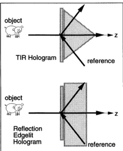
Figure 2.1: A total internal reflection (TIR) hologram and one type of reflection edgelit hologram.
2.2.1
TIR holograms
In 1967, Stetson introduced the total internal reflection (TIR) hologram. The configuration allows very close spacing between the object (usually a two-dimensional transparency) and the hologram; this geometry results in numerous advantages [46]. The TIR hologram is useful for miniaturization in optical integrated cir-cuits [38] and for high-resolution projection imaging [11] such as that required in submicrometer lithography [10]. Other researchers have published on the TIR hologram's characteristics independent from a particular application [12, 37].
Though it has not been explicitly discussed in the literature, the TIR holo-gram and some types of edgelit holoholo-gram have similar structures. The top of Figure 2.1 shows the configuration usually referred to as a TIR recording and reconstruction geometry; below that, one possible reflection edgelit recording ge-ometry is shown. The prism provides the same function for the TIR hologram as the glass block performs for the edgelit hologram. The holographic plate is coupled to the prism or block with a fluid having an index of refraction similar to the glass or emulsion; both prism and block allow the reference beam to exist in the emulsion at a much steeper angle than possible for a beam incident from air. In both cases shown, the reference beam undergoes total internal reflection at the air-emulsion interface. TIR holograms and edgelit reflection holograms that have a totally internally reflected beam have the same basic recording geometry
Figure 2.2: Light ray path down an optical waveguide
and fringe structure (some block-recorded transmission edgelits also have this fringe structure; see Chapter 3 for more on this subject). Many results from
work in TIR holography are, therefore, applicable to the edgelit hologram.
2.2.2
Waveguide holograms (WGH's)
This section begins with a general discussion of waveguides which will later help illuminate the difference between substrate-mode waveguide holograms and thin-film waveguide holograms.
Although anything that guides light can be called a waveguide (Yariv calls a lens system a "lens waveguide" [58]), usually we think of cylindrical fibers or rods, or planar films, slabs, or channels as waveguides. In discussions of optical waveguides usually the distinction is made between guides whose radius or thickness is much greater than the wavelength of light and those, such as fibers and thin films, whose dimensions are on the order of the wavelength of light [17]. This same distinction underlies the difference between substrate-mode WGH's and thin-film WGH's.
To understand the behavior of light in the thicker guides, a simple ray model may be used. A light ray propagates down the guide by successive total internal reflections (Figure 2.2). The minimum angle that will totally internally reflect, called the critical angle 0e, is given by the following equation:
c = sin-1 -" ng
where n is the index of refraction of the material immediately outside the waveguide (shown in the figure as air) and ng is the index of the guiding material. When the dimensions of the guide approach the wavelength of light, however, the propagation becomes more complex. Propagation modes evidencing the wave nature of the light become apparent in the interference patterns (mode patterns) visible at the ends of small diameter fibers, as shown in Figure 2.3 from Hecht [17].
na= 1.00
=>1
Figure 2.3: Waveguide modes evident in the highly magnified ends of fibers (from Hecht).
Understanding propagation modes in fibers or thin films can still begin with the simple ray model, however. All the different ray paths by which a beam can propagate down a guide can be considered different modes. Even in a small di-ameter fiber there can be hundreds or thousands of different ray paths or modes
by which the light can propagate down the fiber (see Figure 2.4 after Hecht [17]).
The different lengths of the different paths give rise to intermodal dispersion, also illustrated in Figure 2.4. As the diameter or thickness of the guide gets smaller, fewer modes can propagate and intermodal dispersion decreases.
The history of waveguide holography begins in 1976 when Suhara et al. made the first use of the term "waveguide hologram" [48]. Though Suhara et al. did little work with evanescent holograms and did not use guided reference beams, they defined the term "waveguide hologram" as a hologram that uses either the evanescent part of a guided wave or the guided wave itself as a reference or illumination source or both. In their experiments, they recorded the holo-gram with free-space reference and object beams, i. e. beams incident on the emulsion from air. They then reconstructed with a guided illumination beam of longer wavelength than the recording wavelength. They recorded with shorter wavelength light in air so that they would get the higher spatial frequency that a guided beam of longer wavelength at a steeper angle would have produced.
Figure 2.4: Waveguide modes (after Hecht).
They recognized that recording in a high index liquid at a steeper angle than achievable in air would also produce the higher spatial frequency fringes (as is the case for the tank-recorded edgelit). (Solymar and Cooke noted that a prism in a geometry, like that used in TIR holography, also can be used to produce higher spatial frequency fringes [44].) Suhara et al.'s recording material usually was sputtered onto a thin-film waveguide that has a lower index of refraction than the recording medium; this ensures that the amplitude of the field is high in the recording medium during reconstruction. Suhara et al. recorded a two-dimensional image in a 1 x 2 mm (0.04 x 0.08 in) hologram. Suhara et al. also reported twin images at reconstruction.
Suhara et al. presented their work as a new method for hologram integra-tion. Subsequently much work in the field of integrated optics uses Suhara et al.'s methods of recording in air with a shorter wavelength than the reconstruc-tion wavelength, using a two-layer waveguide, and recording holograms smaller than 2.5 mm2 (0.1 in2) [2, 42, 23, 24, 30]. Other workers have computer gener-ated their grating patterns and implemented them by one of several methods: etching the pattern into a quartz slab [22], contact printing into photoresist [41], using a double ion exchange process in glass [40], ion milling [1], or creating a nonpermanent photoconductivity grating [36]. Some workers have produced waveguide gratings that use a guided reconstruction beam that diffracts into other guided beams [56, 9]. Most waveguide holography work concentrates on diffractive optical elements such as lenses and gratings for optical intercon-nects, couplers, and other elements in integrated optics. Two papers [48, 2] discussed two-dimensional imaging for integrated optics systems. As mentioned earlier, this work falls under many names: "waveguide holograms" [9, 40, 48, 2], "substrate-mode holograms" [23, 24], "guided-wave holography" [41], variations
of "gratings in waveguides" [49, 56, 36], and several other names. As already
mentioned, all of the of optical integration work is termed waveguide holography in this thesis, and under that heading two subdivisions can the distinguished:
Intermodal dispersion
n.=1.00 1 | |
those guiding in thicker substrates [23, 24, 42, 22, 9] and those guiding in thin films [40, 48, 2, 56, 1, 41].
Those guiding on a thicker substrate are working with holograms that have the same basic structure as the edgelit hologram. As noted above, most of these researchers expose with shorter wavelength light in air, though it is recognized that they could use a beam incident from a tank, block, or prism to achieve the high spatial frequency fringes characteristic of edgelit and waveguide holo-grams. The high spatial frequency fringes are required to diffract light out of the waveguide from its steeply-angled, guided reconstruction beam. Since WGH researchers do not record on a block or prism, total internal reflection can not occur at the recording stage (though strong reflections may still the present). These holograms, therefore, seem most like the tank-recorded edgelit hologram. At first glance, it may appear that a significant difference between this work and edgelit holography work is the thickness of the reconstruction substrate. Most of the WGH researchers reconstruct on a glass waveguide substrate ap-proximately 2.0 -6.5 mm (0.08 - 0.25 mm) thick [42, 39]. In this thesis, these holograms are termed substrate-mode waveguide holograms. As previously men-tioned, the allowable thickness of the substrate depends on the divergence of the reconstruction beam and the size of the hologram. Since most of these holo-grams are only several square millimeters in area and are reconstructed with a guided, undiverged laser beam, they are in many ways simply scaled-down versions of the edgelit hologram.
The relationship between thin-film holography and edgelit holography is more complex, however. Although typical thin-film waveguide holograms are usually quite small-2.5 mm2 (0.1 in2) are the largest reported [2]-the thin-film waveguide has a thickness around 1.5 x 10~3mm or 1500nm (0.06 x 10~6 in) [48].
So, although the hologram itself has a structure like the edgelit (since most of
these holograms are recorded with the same short-wavelength recording method discussed above), the relationship between hologram size and guiding layer is radically different than for the edgelit hologram or the substrate-mode WGH's just discussed. As mentioned at the beginning of the section, the reconstruction beam is much more affected by its guide than reconstruction beams in a thicker material.
One problem with thin-film waveguides is that it is difficult to efficiently couple in a reconstruction beam. The largest beam reported being coupled into a thin-film waveguide had a width of 17mm (0.67in) and was coupled in with an efficiency of 20% [57]. (However, much higher coupling efficiencies are possible for smaller beams.)
Note that none of the thin-film waveguide holography researchers mentioned here record with guided waves, except Wood, who interferes two guided waves
[56].
Though the wave nature of light and resultant propagation modes must be taken into account to fully understand thin-film waveguide holograms, these holograms are still clearly related to the edgelit hologram because they have
a similar fringe structure as the edgelit hologram, extending throughout the emulsion thickness.
2.2.3
Evanescent wave holograms
In 1968, Nassenstein first published on evanescent wave holograms; he then pub-lished a detailed, two-part paper on the subject in 1969 [31, 32]. Nassenstein performed multiple experiments, including recording a three-dimensional image. Bryngdahl, working concurrently but separately, first published his work in 1969
[7]. Bryngdahl also performed multiple experiments, including recording a
two-dimensional image by evanescent holography. Lukosz and Wiithrich published the other most significant work in the field, discussing their work with evanes-cent wave holographic optical elements and two-dimensional imaging [29, 57]. Some researchers whose primary focus is waveguide holography also mention the feasibility of using evanescent waves [48, 30] or use evanescent waves to reconstruct a surface relief hologram [25].
Unlike all the other holograms discussed up to this point, the recording medium for an evanescent hologram is lower in refractive index than its sur-rounds. To produce an evanescent wave in the recording medium, a beam must totally internally reflect in a higher index medium that is in contact with the recording medium. Since all of the holograms previously discussed utilize total internal reflection at some point either in their recording or reconstruction, it is not surprising that previously discussed geometries can be used for the evanes-cent wave hologram. A tank filled with a fluid with higher refractive index than the recording medium can be used to produce the total internal reflection boundary [32, 7]; a geometry employing a prism (as in TIR holography) can be used [32, 29]; or a thin-film waveguide can be used [29, 57].
During reconstruction of evanescent wave holograms, twin output images appear, one on each side of the hologram.
Evanescent wave holograms differ significantly from edgelit, TIR, and waveg-uide holograms. The evanescent wave hologram may or may not have a similar fringe structure to the other three types but, in either case, the structure exists only in a very thin layer of the emulsion if the hologram is recorded with an evanescent wave. (Most researchers in this field both record and reconstruct with the evanescent wave; however, reconstructing a relief hologram with the evanescent wave has been reported [25].) The reason for the thinness of the layer in which the fringe structure appears is that the amplitude of the evanescent wave decreases exponentially with distance from the total internal reflection boundary. As a result, the evanescent wave hologram is approximately 1/16th the thickness of an average 7 pm emulsion [32].
Chapter 3
Fringe structure and
diffraction efficiency
The basic fringe structure of edgelit holograms lies on a continuum between the fringe structures of conventional transmission and reflection holograms, giving rise to some qualities also on such a continuum; other qualities are extremes of the behavior of conventional holograms. Additionally, many edgelit holo-grams have a complex, multiple fringe structure which can result in either a lowered overall diffraction efficiency or an undesirable, rapid variation of diffrac-tion efficiency with reconstrucdiffrac-tion angle. Choice of recording geometry, grating optimization, and emulsion processing can eliminate or reduce these effects.
This chapter compares the fringe structure of conventional holograms with two types of edgelit holograms, using accurately scaled figures that show the fringes resulting from the most common configurations. The diffraction effi-ciency of the edgelit is then tied to its fringe structure and polarization effects. Throughout this thesis, reference and object beams are assumed polarized perpendicular to the plane of incidence unless otherwise specified.
3.1
Fringe structure
3.1.1
Theory
For an accurate visual comparison of the fringe structure of conventional and edgelit holograms, the diagrams in this chapter are to scale (1mm = 113nm) and use actual beam angles. The diagrams are labeled according to the conventions outlined in Appendix B. In all of the particular examples given in this chapter, the emulsion faces the reference beam.
Snell's law, are used. Snell's law states:
n; sin 2 = nt sin t (3.1)
where ni and n are the indices of refraction of the medium in which the beam is incident and transmitted, respectively, and O6 and Ot are the incident and transmitted angles of the beam.
The fringes formed at recording bisect the angle between the object and reference beams, and their angle Of is given by the following expression:
f - Oref + 0ob (3.2)
2
where Of is the fringe angle, and Oref and Gobj are the reference and object angles, respectively, measured in the same medium (air, emulsion, glass, etc. ). The spacing of the fringes (the perpendicular distance between them) A is given by
A A/n
2 sin I0ref -9bj'
2
where A is the recording wavelength, n is the index of refraction of the emulsion, and 6',f and 6'bj are the reference and angles in the emulsion.
The distance d between the fringes as measured along the surface of the emulsion is given by
A/n sin 0'- ref sin 0'obj
(See Appendix A for a derivation of this equation showing that it should apply to the edgelit.)
The spatial frequency f of the hologram's interference pattern is given by
1/d and is usually specified in cycles per millimeter (cy/mm).
3.1.2
Conventional holograms
In this section the conventional transmission and reflection examples use a 450
reference beam typical of these types of hologram. The angles in the figures, however, are labeled by the 3600 convention since that convention is used in the computation of the fringe structure. For the examples in this section, the emulsion faces the reference beam.
Transmission holograms are recorded when both the object and reference beams approach the emulsion from the same side of the plate. In this example, the reference beam is incident on the emulsion at 45* and the object beam is incident at 00 (see Figure 3.1). Assuming the emulsion has an index of refraction of 1.63, the intra-emulsion reference angle is 25.7*, according to Snell's law.
The fringes of the transmission hologram in our example are at 13* and are shown in Figure 3.2 (for the simplified case in which both object and reference
Figure 3.1: A typical transmission hologram and its beam angles at recording.
f = 1117 cy/mm
object
reference
na= 1.00 n .3n=15
(air) (emulsion) (glass)
~7pm = 7000nm =633 nm
Figure 3.3: A typical reflection hologram and its beam angles at recording.
beams are collimated plane waves). If the recording wavelength A is 633 nm, the fringe spacing A is 873nm. The distance between the fringes along the emulsion
d is 896 nm for this example, so the spatial frequency is 1117 cy/mm.
Reflection holograms are recorded when the object and reference beams ap-proach the emulsion from opposite sides (see Figure 3.3). The reference beam for our example is incident on the emulsion at 1350 (450 by the 90*
angle-labeling convention; see Appendix B), which is 154* in the emulsion. Fringe spacing A = 199 nm, distance between fringes along the surface of the
emul-sion d = 896 nm, and spatial frequency
f
= 1117 cy/mm in Figure 3.4. Notethat the distance between fringes at the surface of the hologram (and, therefore, the spatial frequency) of the reflection and transmission holograms is identical. Also note the extreme difference in fringe angle and spacing within the emulsion between the transmission and reflection holograms.
Gref =135* 45* Z robj r0* object reference
A = 199 nm ref = 154.3* f 1117 cy/mm
Gref
=135* d 896 nm Of =77.15*Gobj
=0* reference n=151 n= 130(glass) (emulsion)_ (air)
~7 pm 7000 nm
X=633
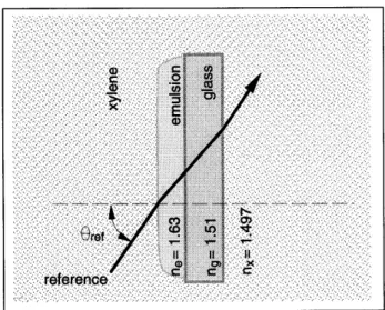
nmFigure 3.5: Schematic of a typical referencing geometry for a tank-recorded edgelit: a holographic plate (glass and emulsion) is immersed a liquid having an index of refraction similar to the indices of glass and emulsion.
3.1.3
Edgelit holograms
The primary fringe structure of both transmission and reflection edgelit holo-grams can be thought of as a blend between the fringe structures of conventional transmission and reflection holograms. Many edgelit recording geometries, how-ever, also produce a secondary fringe structure that can be almost as strong as the primary structure. This secondary fringe structure is formed by the in-terference of the object beam with that portion of the reference beam that is reflected off the second emulsion interface. Many other sets of fringes caused
by reflections can also occur depending on the edgelit recording geometry used
and can degrade the quantity of the hologram. See Appendix D for more on reflections in edgelit versus conventional hologram recording geometries.
To minimize the amount of light lost to reflection, edgelit holograms are usu-ally recorded with the reference beam incident on the emulsion from a material with an index of refraction similar to the emulsion's. Usually this material is an index-coupling fluid in a tank or a thick block of glass coupled to the holographic plate. Figure 3.5 shows the holographic plate immersed in xylene, a common index-coupling fluid with an index of refraction of 1.497. Figure 3.6 shows the holographic plate couple to a glass block with xylene. In both figures, only the reference beam is shown because the object beam may approach the plate from either side.
An idealized tank-recording geometry produces only the edgelit hologram's
0::i1
Gref
-Jreference
C*
c c COFigure 3.6: Schematic of a typical referencing geometry for a block-recorded edgelit: a holographic plate (glass and emulsion) is coupled to a glass block with a fluid having an index of refraction similar to the indices of glass and emulsion.