II. DEVELOPMENTAL ELECTRON OPTICS LABORATORY Academic and Research Staff
Dr. J.W. Coleman
1. THE AUGER ELECTRON MICROSCOPE
Joint Services Electronics Program (Contract DAAG29-78-C-0020) National Institutes of Health (Grant 1 ROI GM23597)
John W. Coleman
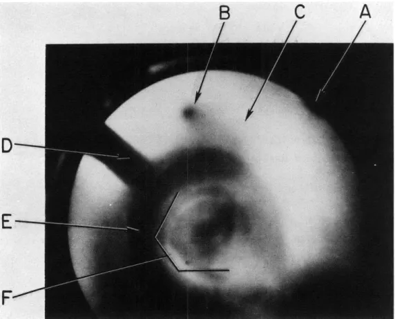
The Auger Electron Microscope has yielded Auger + secondary dark-field images of carbon on tungsten, with spatial resolutions of %0.8 p and energy resolution of <20 eV. A typical AEM micrograph is shown in Fig. II-1. The main limitations at present to better resolution of either type are
1. the lack of a facility for alignment of the optical column elements while images are being observed;
2. the influence of slowly varying residual stray fields; and 3. the lack of highly regulated power supplies.
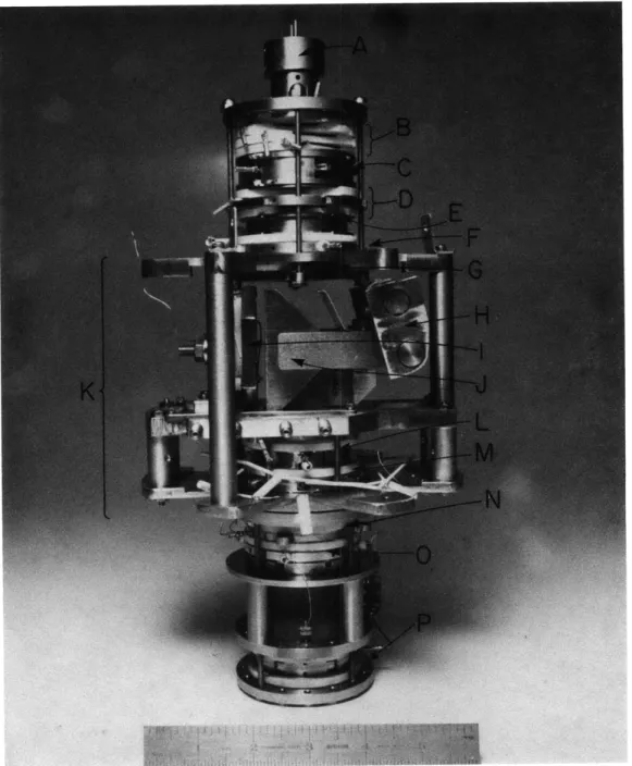
The total electron-optics package (minus the chevron electron multiplier array used as output) is shown in Fig. 11-2, and the overall instrument is seen in Fig.
11-3.
With the elimination of the problems listed above, the instrument should con-verge on its theoretical performance level, whereby eventually we expect spatial resolutions of a few angstroms and energy resolutions of a few eV to be demon-strated.
Fig. II-i. AEM micrograph of butt end of 3-mil diam tungsten wire which has been rubbed on graphite. (Low-mag image (330X) taken with Polaroid camera directly from Chevron Electron Multiplier Array phosphor screen, as seen through vacuum window (see-Fig. II-3). The CEMA current gain is 1.5 x 10⁶.) The parts of the figure are as follows:
A - Periphery of CEMA phosphor screen B - A CEMA defect (burnout point)
C - Scattered electrons of no interest (eventually to be aper-tured out when alignment permits)
D - Support portion of L-shaped tungsten wire, seen as shadow image
E - Dark-field background due to on-axis portion of tungsten wire F - Auger + secondary image of carbon embedment.
It should be noted that the butt end or specimen end of the wire is pointing away from the phosphor screen, and that the primary dark-field image appears between the specimen end of the wire and the phosphor screen. The situation is analogous to seeing a person's face against the background of the back of his head, and is a consequence of the mirror optics necessary for a high-efficiency collection of Auger
electrons.
Fig. 11-2. AEM electron-optics package. A - Electron gun for excitation
of Augers in specimen
B - Auger mirror-objective lens C - Specimen-holder drawer D - Accelerator
E - Set-up lens for energy analyzer F - Deflector ring
G - Spherical-aberration-corrector foil
H - Magnetic-prism winding assembly
I - Analyzer-mirror cathode J - Magnetic prism
K - Energy-analyzer assembly L - Projector-discriminator M - Deflector ring and
stigmator N - Projector #2
0 - Deflector ring P - Projector #3.
Fig. 11-3. PR No. 122 E~:E~ :8 i,~ --' ~- ---6 $ i g"i ~