HAL Id: tel-02269108
https://tel.archives-ouvertes.fr/tel-02269108
Submitted on 22 Aug 2019HAL is a multi-disciplinary open access archive for the deposit and dissemination of sci-entific research documents, whether they are pub-lished or not. The documents may come from teaching and research institutions in France or abroad, or from public or private research centers.
L’archive ouverte pluridisciplinaire HAL, est destinée au dépôt et à la diffusion de documents scientifiques de niveau recherche, publiés ou non, émanant des établissements d’enseignement et de recherche français ou étrangers, des laboratoires publics ou privés.
Lanthanide Energy Transfer Donors on Nanoparticles
Surfaces : From Fundamental Mechanisms to
Multiplexed Biosensing
Chi Chen
To cite this version:
Chi Chen. Lanthanide Energy Transfer Donors on Nanoparticles Surfaces : From Fundamental Mech-anisms to Multiplexed Biosensing. Micro and nanotechnologies/Microelectronics. Université Paris Saclay (COmUE), 2019. English. �NNT : 2019SACLS196�. �tel-02269108�
Lanthanide Energy Transfer
Donors on Nanoparticles Surfaces:
From Fundamental Mechanisms to
Multiplexed Biosensing
Thèse de doctorat de l'Université Paris-Saclay Préparée à l'Université Paris-Sud
École doctorale n°575 : electrical, optical, bio : physics and engineering (EOBE)
Spécialité de doctorat: Physique (Electronique et Optoélectronique, Nano et Microtechnologies)
Thèse présentée et soutenue à Orsay, le 5 Juillet 2019, par
M. Chi Chen
Composition du Jury : Mme Fabienne Mérola
Directrice de Recherche, Université Paris-Sud Présidente
Mme Adriana Zaleska-Medynska
Professeur, University of Gdansk Rapporteur
M. Thomas Just Sørensen
Professeur, University of Copenhagen Rapporteur
M. Christophe Dubessy
Maître de Conférences, Université de Rouen Examinateur
M. Niko Hildebrandt
Professeur, Université Paris-Sud Directeur de thèse
NNT : 2 0 1 9 S A CL S 1 9 6
Université Paris-Saclay
Espace Technologique / Immeuble Discovery
Route de l’Orme aux Merisiers RD 128 / 91190 Saint-Aubin, France
Titre : Transfert d'énergie entre lanthanides et nanoparticules: des mécanismes fondamentaux aux biosenseurs multiplexés
Mots clés : points quantiques, terbium, multiplexage, fluorescence, code à barres, FRET Résumé : Le multiplexage optique basé sur des
nanoparticules offre de nombreux avantages pour la biodétection et l'imagerie à multiparamètres. Toutefois, les modifications apportées à un paramètre entraînent également la modification d’autres paramètres. Par conséquent, la couleur, la durée de vie ou l’intensité ne peuvent pas être utilisées, respectivement, comme paramètre indépendant. Cette thèse peut être divisée en deux aspects. Le premier concerne le développement d'un multiplexage à une seule nanoparticule avec un temps résolu, basé sur le transfert d'énergie par résonance de type Förster (FRET) des complexes de lanthanides aux points quantiques (QD) et ensuite aux colorants fluorescents. Une investigation systématique de toutes les différentes combinaisons avec une large gamme de donneurs et d'accepteurs sur le QD est
présentée, et les résultats expérimentaux sont comparés à la modélisation théorique. Le résultat ne contribue pas seulement à une compréhension complète de ces voies de transfert d'énergie compliquée entre multi donneurs / accepteurs sur des nanoparticules, mais offre également la possibilité d'utiliser les modèles pour développer de nouvelles stratégies permettant de preparer le QD avec une couleur, une durée de vie et une intensité réglables de manière indépendante. Le deuxième aspect porte sur le mécanisme de transfert d'énergie du Tb à la nanoparticule d'or (AuNP). Le transfert d'énergie par nanosurface (NSET) s'est révélé être un mécanisme opérationnel pour l'extinction des PL par les AuNP, une information importante pour le développement, la caractérisation et l'application de nanobiocapteurs basés sur l'extinction des PL par les AuNP.
Title : Lanthanide energy transfer donors on nanoparticles surfaces: from fundamental mechanisms to multiplexed biosensing
Keywords : quantum dots, terbium, multiplexing, fluorescence, barcoding, FRET Abstract : Optical multiplexing based on
nanoparticles provides many advantages for multiparameter biosensing and imaging. However, the changes in one parameter also lead to changing of other parameters, and thus, color, lifetime, or intensity could not be used as an independent parameter, respectively. This thesis can be divided into two aspects. The first one focuses on developing time-resolved single-nanoparticle multiplexing based on Förster resonance energy transfer (FRET) from lanthanide complexes to quantum dot (QD) to fluorescent dyes. Systematical investigation of all different combinations with a broad range of numbers of donors and acceptors on QD are presented, and the experimental results are
compared with theoretical modelling. The result do not only contribute to a full understanding of such complicated multi donor-acceptor energy transfer pathways on nanoparticles but also open the opportunity to use the models for developing new strategies to achieve the QD with independent tunable color, lifetime and intensity. The second aspect focuses on the energy transfer mechanism from Tb to gold nanoparticle (AuNP). Nanosurface energy transfer (NSET) proved to be an operational mechanism in PL quenching by AuNPs, which is important information for the development, characterization, and application of nanobiosensors based on PL quenching by AuNPs.
Acknowledgment
First and foremost I would like to express my special appreciation my supervisor Prof. Niko Hildebrandt, who provided many precious opportunities and constant support during my PhD and acted as a role model to me not only academically but also in life. There are many things Niko has taught me, but nothings was more precious than his enthusiasm to pursue pure science and push the boundaries of human knowledge (e.g., FRET). I still remember one day we discussed a huge and complicated work, and he said: “I know all of this takes a long time but this is what science is actually about. We need to remember that we are primarily making science for science and not for our career. ”
I thank Prof. Adriana Zaleska-Medynska and Prof. Thomas Just Sørensen for being the reviewers of my PhD thesis.
I also want to thank our collaborators Dr. Liang Huang, Dr. Martinus H. V. Werts, Dr. Jurriaan M. Zwier, and Prof. Ben Corry for their kindness, availability and scientific support, and all the co-authors of my publications.
Many thanks to all former and current members of the NanoBioPhotonics group. My special thanks to Dr. Shashi Bhuckory, Dr. Yu-Tang Wu, and Dr. Xue Qiu for their continuous guidance, patience and valuable time devoted in sharing their technical and scientific knowledge with me. I also thank Dr. Marcelina Cardoso Dos Santos, Vjona Cifliku, and Meryem Sennad for cell culture.
I also want to thank Carlos Mingoes and Tudor Haruta for translating in hospital when I was injured, Dr. Xavier Zambrana Puyalto for suggesting the funny book
“Surely You're Joking, Mr. Feynman!”, Dr. Akram Yahia-Ammar for translating in CPMA, Dr. Mariia Dekaliuk for helping to find a nice apartment near our lab, Jiajia Guo and Jingyue Xu for providing real hot food when I first came to France, and Bilguissou Diallo for her help with translation of my abstract,
I thank the IDEX Paris-Saclay (Investissements d’avenir) for my PhD fellowship.
Of course, thanks must go to my parents. They do not speak English and have no idea what nanophotonics is, but they always try their best to support and encourage me in every possible way.
Last but not least, my deepest gratitude goes to my wonderful wife Xin Geng. Although she is not a scientist, she always listens curiously to me for sharing my research ideas. The idea of single-nanoparticle barcoding is inspired from a talk in which I want to explain her the spectroscopic ruler. Without her companionship and encouragement, it would have been impossible for me to go through the last three years with full of enthusiasm.
These days in Paris were the happiest three years I have had. Not only FRET theory from “Captain FRET”, I also learned a lot of art and culture knowledge from the museums. Thanks to everyone I have met along the way.
List of publications
Original publications
1. Chi Chen, Ben Corry, Liang Huang, Niko Hildebrandt. FRET-Modulated Multihybrid Nanoparticles for Brightness-Equalized Single-Wavelength Barcoding. Journal of the American Chemical Society 2019, 141, 11123-11141. 2. Chi Chen, Lijiao Ao, Yu-Tang Wu, Vjona Cifliku, Marcelina Cardoso Dos Santos, Emmanuel Bourrier, Martina Delbianco, David Parker, Jurriaan M. Zwier, Liang Huang, Niko Hildebrandt. Single-Nanoparticle Cell Barcoding by Tunable FRET from Lanthanides to Quantum Dots. Angewandte Chemie International Edition
2018, 41, 13686-13690.
3. Chi Chen, Clyde Midelet, Shashi Bhuckory, Niko Hildebrandt, and Martinus H. V. Werts. Nanosurface Energy Transfer from Long-Lifetime Terbium Donors to Gold Nanoparticles. The Journal of Physical Chemistry C 2018, 122, 17566-17574. 4. Chi Chen, Pengfei Zhang, Li Zhang, Duyang Gao, Guanhui Gao, Yong Yang, Wenjun Li, Ping Gong, Lintao Cai. Long-Decay Near-Infrared-Emitting Doped-Quantum Dots for Lifetime-Based in Vivo pH Imaging. Chemical Communications
2015, 51, 11162-11165.
5. Chi Chen, Pengfei Zhang, Guanhui Gao, Duyang Gao, Yong Yang, Hong Liu, Yuhui Wang, Ping Gong, Lintao Cai. Near-Infrared-Emitting Two-Dimensional Codes Based on Lattice-Strained Core/(Doped) Shell Quantum Dots with Long Fluorescence Lifetime. Advanced Material 2014, 26, 6313-6317.
6. Chi Chen, Xuewen He, Li Gao, Nan Ma. Cation Exchange-Based Facile Aqueous Synthesis of Small, Stable, and Nontoxic Near-Infrared Ag2Te/ZnS Core/Shell
Quantum Dots Emitting in the Second Biological Window. ACS Applied Materials
& Interfaces 2013, 5, 1149-1155.
7. Guanhui Gao, Chi Chen, Xiaobin Xie, Yantao Su, Shendong Kang, Guichi Zhu, Duyang Gao, Achim Trampert, Lintao Cai. Toward Edges-Rich MoS2 Layers via
Chemical Liquid Exfoliation Triggering Distinctive Magnetism. Materials
Research Letters 2017, 5, 267-275.
8. Li Zhang, Chi Chen, Wenjun Li, Guanhui Gao, Ping Gong, Lintao Cai. Living Cell Multilifetime Encoding Based on Lifetime-Tunable Latticed-Strained Quantum Dots. ACS Applied Materials & Interfaces 2016, 8, 13187-13191.
Oral presentations
1. Chi Chen, Niko Hildebrandt. Live-Cell Encoding by Single-Nanoparticle FRET Multiplexing. ACS National Meeting & Exposition, Orlando, USA, 2019, 31/03-04/04.
2. Chi Chen, Niko Hildebrandt. Particle Encoding using Terbium-to-Quantum Dot FRET. 8th International Colloids conference, Shanghai, China, 2018, 10/06-13/06.
Poster presentations
1. Chi Chen, Clyde Midelet, Shashi Bhuckory, Martinus H. V. Werts, Niko Hildebrandt. Resonance Energy Transfer to Gold Nanoparticles Explained by Long-Lifetime Terbium Donors. 10th International Conference on f-Elements
Contents
1. Introduction ... 1
2. Background ... 7
2.1 Förster resonance energy transfer ... 7
2.1.1 Förster resonance energy transfer theory ... 8
2.1.2 FRET with multiple donors and/or acceptors ...12
2.2 Quantum dots ...13
2.2.1 Optical properties...14
2.2.2 Surface functionalization ...16
2.2.3 QD as FRET donor/acceptor/relay ...18
2.3 Luminescent lanthanides ...24
2.3.1 Luminescent lanthanide complexes and nanoparticles ...25
2.3.2 Lanthanide complexes as FRET donor ...29
2.4 Fluorescent dyes ...32
2.4.1 Dye aggregates ...33
2.4.2 Homo FRET ...34
2.5 Gold nanoparticles ...35
2.5.1 Surface plasmon resonance ...36
2.5.2 Nanosurface energy transfer theory ...36
2.6 Time-resolved measurement ...38
2.6.1 Time-gated measurement ...39
2.6.2 Lifetime measurement ...40
2.6.3 Time to multiplex ...42
3. Lanthanides complex to QD FRET based cell barcoding ...45
3.1 Introduction ...45
3.2.1 Materials ...47
3.2.2 Synthesis of QD embedded silica nanpspheres ...48
3.2.3 Synthesis of mercapto-terminated silica nanospheres ...48
3.2.4 Estimation of molar concentration of QD/SiO2 ...48
3.2.5 Formation of mTb-QD/SiO2 donor-acceptor assemblies ...49
3.2.6 Formation of Eu-QD/SiO2 donor-acceptor assemblies ...49
3.2.7 Cell culture ...50
3.2.8 Living cell encoding...50
3.2.9 Cytotoxicity Measurements ...51
3.2.10 Analytical methods ...51
3.2.11 FRET calculation ...51
3.2.12 Multi-exponential PL decay analysis. ...52
3.3 Results and discussion ...53
3.3.1 Characterization of Ln (Tb/Eu)-QD assemblies ...53
3.3.2 Living cell encoding...57
3.4 Conclusion ...62
4. FRET-modulated multi-hybrid nanoparticles for brightness-equalized barcoding ...64
4.1 Introduction ...64
4.2 Materials and methods ...67
4.2.1 Materials ...67
4.2.2 Synthesis of QDs embedded silica nanospheres ...68
4.2.3 Synthesis of mercapto-terminated silica nanospheres ...68
4.2.4 Estimation of molar concentrations of QD/SiO2 ...68
4.2.5 Photoluminescence quantum yield determination ...69
4.2.6 Determination of Tb3+ to Lumi4-ligand ratio for ~100% coordination ...69
4.2.8 Formation of FRET system 2 (QD-nCy5.5) ...70
4.2.9 Formation of FRET system 3 (mTb-QD-15Cy5.5) ...71
4.2.10 Formation of FRET system 4 (75Tb-QD-nCy5.5) ...71
4.2.11 Fabrication of FRET-modulated multi-hybrid nanoparticles for brightness-equalized single-wavelength barcoding. ...72
4.2.12 Microbeads encoding ...73
4.2.13 Analytical Methods ...73
4.2.14 FRET calculation ...74
4.2.15 Multi-exponential PL decay analysis ...76
4.3 Results and discussion ...76
4.3.1 Design and preparation of the multi-hybrid FRET nanoparticles ...76
4.3.2 Photophysical characterization of the multi-hybrid FRET nanoparticles ...81
4.3.3 FRET system 1: mTb-QD ...83
4.3.4 FRET system 2: QD-nCy5.5. ...87
4.3.5 FRET system 3: mTb-QD-15Cy5.5 ...91
4.3.6 FRET system 4: 75Tb-QD-nCy5.5 ...94
4.3.7 Brightness-equalized barcoding ...99
4.4 Conclusion ... 104
5. Energy transfer from Tb donors to AuNPs... 106
5.1 Introduction ... 106
5.2 Materials and methods ... 108
5.2.1 Materials ... 108
5.2.2 Optimization of buffer conditions ... 109
5.2.3 Formation of Tb/AuNP donor-acceptor assemblies ... 109
5.2.4 Analytical Methods ... 110
5.3.1 Characterization of Tb-sAv-biot-AuNP assemblies ... 111
5.3.2 Time-resolved PL decay analysis ... 115
5.3.3 Energy transfer mechanism: FRET vs NSET ... 117
5.4 Conclusion ... 122
6. Summary and outlook ... 124
7. Appendix ... 126
7.1 Abbreviations ... 126
7.2 Simulation methods ... 130
7.3 FRET-modulated multi-hybrid nanoparticles ... 133
7.4 Energy transfer from Tb donors to AuNPs ... 148
7.4.1 Stability of the AuNPs in buffer ... 148
7.4.2 Time-resolved PL decays of Tb-sAv-biot-AuNP assemblies ... 149
7.4.3 Analysis of Tb PL decays for 5 nm, 30 nm, 50 nm and 80 nm AuNPs using Kohlrausch decay laws ... 155
8. Bibliography ... 161
1
1. Introduction
“Every science begins as philosophy and ends as art; it arises in hypothesis and flows into achievement.”
— Will Durant
This sentence is from a book called “The Story of Philosophy”. Or we also can call it “The beauty of Philosophy”. We know the natural philosophy is considered to be the precursor of natural science. But why every science ends as art? What is art? In my opinion, art is the expression of imaginative, conceptual, original ideas with technical skill and emotional power, or we can say beauty is art. Euler's Identity shows a profound connection between the most fundamental numbers in mathematics and exhibits the mathematical beauty. Maxwell’s Equations establish unified electromagnetic theory. They bring together electricity, magnetism, and light as different manifestations of the same phenomenon, and show the physical beauty. I also want to discovery the beauty in my research field, and I believe it has been there.
The aim of this thesis is to study the Förster resonance energy transfer (FRET) mechanism in lanthanides-quantum dot (QD)-fluorescent dyes systems and utilize the FRET modulated multi-hybrid nanoparticle for time-resolved multiplexing, and the study of energy transfer mechanism from long lifetime Tb donors to gold nanoparticles (AuNPs). Time-resolved multiplexing has many advantages, and we also find the beauty of time based multiplexing. The three temporal optical detection windows can be regarded as metaphor of the three clocks in Dali’s “The Persistence of Memory” (Figure 1.1 right). Inspired by this painting, we designed this picture (Figure 1.1 left), in which the three clocks with red, green, and blue color perfectly represent the idea of that were used for RGB (red, green, blue) barcoding. Other elements in this painting have also been replaced by the materials using in our study, including a single-nanoparticle assembly (orange
2
clock covered by ants in the original) on the bottom left, a microscope objective (the “monster” in the original) in the center (below the blue clock), and a microscope slide with encoding cells (the platform or pool in the original) on the top left.
Figure 1.1. The imitative work of “The Persistence of Memory” (left) and the original painting by
Salvador Dali (right).
The first study (Chapter 3) demonstrates the possibility of single-nanoparticle cell barcoding based on lanthanides complex to QD FRET. In order to obtain the optical encoding with higher capacity, the majority of principle was mixing of different luminescent molecules or nanoparticles in microbeads or cells. Designing different concentration-independent codes without mixing various nanoparticles and by using single-wavelength excitation and emission for multiplexed imaging is extremely challenging. As illustrated in Figure 1.2, we report the synthesis of QDs coated with SiO2 of different shell thicknesses (6 and 12 nm). Attachment of
lanthanide (Ln) complexes (Tb and Eu) with long photoluminescence(PL)-lifetimes on the SiO2 shells resulted in different Ln-to-QD distances, which, in turn, led to
different PL decay times due to distance-dependent FRET. Thus, four specific QD PL decays (all at 640 nm upon excitation of the Ln complexes at 349 nm) were designed with Tb-QD (SiO2-6nm), Tb-QD (SiO2-12nm), Eu-QD (SiO2-6nm), and
Eu-QD (SiO2-12nm) and used as well-defined single-particle codes to label live cells.
To recognize the live-cell codes, time-gated fluorescence microscopy was employed and four different cell types could be distinguished by a single measurement. The
3
donors with various Ln complexes and QD acceptors with different colors. Thus, our time-gated Ln-to-QD FRET concept has the potential to significantly advance fluorescence cell-encoding. However, one important drawback of this strategy is the significant variation in brightness of the different codes. We will address this issue in the second study.
Figure 1.2. (a) QDs with SiO2 coatings of different thicknesses (x=6 or 12 nm) functionalized with
Eu-1 or Lumi4-Tb for single-wavelength temporal PL barcoding. (b) The RGB encoding principle based on three distinct TG PL intensity fractions for each of the four FRET-specific PL decays and four encoded cells.
The second study (Chapter 4) focuses on multiple donor-acceptor FRET systems with QDs. QDs are the most versatile fluorophores for FRET because they can function as both donor and acceptor for a multitude of fluorophores attached to their surface. However, a complete understanding of multi-donor-acceptor FRET networks on QDs and their full employment into advanced fluorescence sensing and imaging have not been accomplished. In this chapter, we provide a holistic photophysical analysis of such multi-donor-QD-multi-acceptor FRET systems using time-resolved and steady-state PL spectroscopy and Monte Carlo simulations. Multiple terbium-complex (Tb) donors (1 to 191 units) and Cy5.5 dye acceptors (1 to 60 units) were attached to a central QD and the entire range of combinations of single and multiple FRET pathways was investigated by Tb, QD,
4
and Cy5.5 PL. Experimental and simulation results were in excellent agreement and could disentangle the distinct contributions of hetero-FRET, homo-FRET, and dye-dimerization. The FRET efficiency was independent of the number of Tb donors and dependent of the number of Cy5.5 acceptors, which could be used to independently adapt the PL intensity by the number of Tb donors and PL lifetime by the number of Cy5.5 acceptors. As shown in Figure 1.3, we used this unique tuning capability to prepare Tb-QD-Cy5.5 conjugates with distinct QD PL lifetimes but similar QD PL intensities. These brightness-equalized multi-hybrid FRET nanoparticles were applied to optical barcoding via three time-gated PL intensity detection windows, which resulted in an encoding of the distinct PL decay curves into simple RGB ratios. Direct applicability was demonstrated by an efficient RGB distinction of different nanoparticle-encoded microbeads within the same field of view with both single-wavelength excitation and detection on a standard fluorescence microscope. In addition to imaging and biosensing, controlled photophysical tuning of FRET-modulated multi-hybrid QDs for single-wavelength PL encoding has the potential to advance other photonic applications, such as data storage, security labeling, optogenetics, or molecular computing.
Figure 1.3. FRET-modulated multi-hybrid nanoparticles for brightness-equalized
single-wavelength barcoding.
In the third study (Chapter 5) we attempt to understand the energy transfer mechanism from long lifetime Tb donors to AuNPs. The application of PL quenching by AuNPs has expanded the applicability of optical probe methodologies in biochemistry, biodiagnostics, and biomolecular imaging. Understanding the
5
energy transfer mechanism plays a fundamental role in developing optical ruler methodologies. Both Förster resonance energy transfer (FRET, ~R-6 distance
dependence) and nanosurface energy transfer (NSET, ~R-4 distance dependence)
have been considered as the correct theory for the quenching mechanism. However, the significant differences of the distance dependence of both resonance energy transfer mechanisms can lead to strong variations in the energy transfer process. In this chapter, we investigate PL lifetime quenching of terbium complexes (Tb) conjugated to streptavidin when bound to biotinylated Au-NPs of different diameters (5, 30, 50, and 80 nm)(Figure 1.4). The binding of Tb-labeled streptavidin (Tb-sAv) to biotinylated AuNPs (biot-AuNPs) was studied using light-scattering spectroscopy. Quenching of the PL of Tb-sAv upon binding to biot-AuNPs of different diameters (5, 30, 50, 80 nm) was studied by time-resolved PL spectroscopy. Energy-transfer efficiencies were found to be practically independent of the AuNP size. Analysis according to FRET theory yielded donor−acceptor distances that were inconsistent and far beyond the expected Tb−AuNP distance. In contrast, the NSET model yielded a good agreement between the Tb-to-AuNP surface distance estimated from the geometry of the Tb-sAv/biotin-AuNP assembly (4.5 nm) and those calculated from PL lifetime analysis, which range from 4.0 to 6.3 nm. Our findings strongly suggest that NSET (and not FRET) is the operational mechanism in PL quenching by AuNPs, which is important information for the development, characterization and application of nanobiosensors based on PL quenching by AuNPs.
6
After this introduction, a theoretical background on resonance energy transfer, QDs, luminescent lanthanides, fluorescent dyes, AuNPs, and time-resolved measurement will be presented (Chapter 2). Three experimental studies will follow in a paper-style with an introduction, materials and method, results and discussion, and a conclusion. A summary addressing the results obtained from the experimental studies will be discussed and an outlook on future research. Appendix and bibliography follow at the end of the thesis.
7
2. Background
This chapter will introduce basic knowledge of Förster resonance energy transfer (FRET) mechanisms, quantum dots (QDs), luminescent lanthanides, fluorescent dyes, gold nanoparticles (AuNPs), and time-resolved (TR) measurement in an attempt to understand how to design and perform lanthanides-to-QDs D-A pairs based FRET and lanthanides-to-AuNPs pairs based NSET experiment. In particular, we are interested in studying the multiple donors and acceptors based FRET model for calculating desired photophysical properties adapted to advanced fluorescence biosensing and imaging applications. The understanding of such a model will be facilitated by a deep understanding of such complicated multi donor-acceptor energy transfer pathways on nanoparticles.
This chapter will be organized by first examining in Section (2.1) FRET mechanism in terms of FRET theory, multiple donors and/or acceptors FRET.
Section (2.2) will examine optical properties and surface functionalization of QDs,
and how QDs can server as donor, acceptor, or relay. The next Section (2.3) will examine photophysics of luminescent lanthanide complexes and nanoparticle, and the advantage of lanthanide complexes in donor based FRET. Section (2.4) will focus on dye aggregates and homo FRET of fluorescent dyes. Section (2.5) will focus on the surface plasmon resonance (SPR) and nanosurface energy transfer (NSET) of AuNPs. Finally, Section (2.6) will examine the TR measurement and TR based optical multiplexing.
2.1 Förster resonance energy transfer
Resonance energy transfer (RET) is based on the concept of a fluorophore as an oscillating dipole, which can exchange energy with another dipole with a similar resonance frequency.[1] The best known RET mechanism is Förster resonance energy transfer (FRET), which is considered to occur when the donor and acceptor can be reasonably approximated as point dipoles. For the observation of FRET, the following conditions should be met:[2]
8
(ii) Spectral overlap must exist between the emission of donor and the absorption of acceptor.
(iii) Donor and acceptor must be close, but not too close. (iv) The orientation factor should not be zero.
In addition, when the excited state donor is created through a chemical reaction or enzyme-catalyzed biochemical reaction, the RET phenomena are referred to as bioluminescence or chemiluminescence resonance energy transfer (BRET or CRET), respectively. In general, Förster theory applies equal well to both of them. The FRET mechanism does not generally apply in cases where the donor or acceptor cannot be approximated as a point dipole, which frequently occurs with energy transfer to metal surfaces. The latter are more appropriately described as nanosurface energy transfer (NSET). The discussion below will present some very basic knowledge and mathematics needed of FRET theory (2.1.1), multiple donors and/or acceptors based FRET (2.1.2) to design and perform FRET based experiments, and is mainly extracted from reference [2].
2.1.1 Förster resonance energy transfer theory
Förster resonance energy transfer (FRET) is an electrodynamic phenomenon, and the theory behind resonance energy transfer was mainly contributed by Theodor Förster in 1940s.[2] FRET is a nonradiative energy transfer process between a donor (D) molecule in the excited state and an acceptor (A) molecule in the ground state with an efficiency that is dependent on the distance R-6 between D and A.
FRET occurs without the appearance of a photon and is the result of long range dipole–dipole interactions between the donor and acceptor. It can be represented by Coulombic coupling (coupling of two charges) VCoul. VCoul should be dominant at
the distance range of 1-20 nm, which is usually considered FRET distance. In this case, orbital overlap-related mechanisms and radiative mechanisms play minor roles. The FRET rate can be represented by Fermi’s golden rule (Equation 2.1):
𝑘FRET =2𝜋
ℏ |𝑉|
2𝜌 (2.1)
Where ℏ is the reduced Planck constant, V is the electronic coupling between D and A, and ρ is the density of the interacting initial and final energetic states,
9
which is related to the spectral overlap integral J (the overlap of D emission and A absorption, defined in the wavelength or wavenumber scale). In Equation 2.1, V can be replaced by the R-3 distance dependent 𝑉Coul (Equation 2.2):
𝑉Coul =4𝜋𝜀𝜅|𝜇⃗⃗ D||𝜇⃗⃗ A|
0𝑛2𝑅3 (2.2)
Where 𝜇 D and 𝜇 A are the transition dipole moments of D and A, 𝜅 is the orientation factor between them, 𝜀0 is the vacuum permittivity, n is the refractive index, and
R is the distance between D and A.
After substituting Equation 2.2 into Equation 2.1, the FRET rate can be descripted as following Equation 2.3:
𝑘FRET= 9 (ln10)𝜅
2Φ D
128𝜋5𝑁A𝑛4𝜏D𝑅6𝐽 (2.3)
Where ΦD is the luminescence quantum yield of D in absence of energy transfer,
𝑁A is Avogadro’s number (6.023 × 10²³ mol-1), and 𝜏
D is the luminescence lifetime
of D.
Figure 2.1. (Left) Basic FRET principle. In the Jablonski diagram (simplified energy level
scheme), the donor is excited by hv from an electronic ground state (D) to an excited state (D*), and then goes to an excited electronic ground state by inner relaxation (vibrational and rotational-dotted arrow), and finally goes back to ground state by radiative decay (𝑘R), nonradiative decay (𝑘NR), or FRET (𝑘
FRET). The FRET process happens when the difference between the respective energy levels are equal, in other words the donor and acceptor share the same electronic transitions (horizontal lines with dots on each end). After FRET, the acceptor is in an excited state (A*), then goes to its ground state (A) by radiative or nonradiative decay. (Right) The overlap (gray area) of the area normalized emission spectrum of D (cf. Equation 2.6) and the molar absorptivity spectrum of A (𝜀A) defines the overlap integral J (cf. Equation 2.5). (Adapted from reference [2]. Copyright 2013 Wiley-VCH Verlag GmbH & Co. KGaA)
10
2.1 (left), electronic transitions from a higher to a lower energy level in D lead to
electronic transitions from a lower to higher energy level in A, if these transitions are in energetic resonance.
Förster distance (R0), at which energy transfer and spontaneous decay of the
excited donor are equally probable (𝑘FRET= 𝑘DR+ 𝑘DNR= 𝜏D−1), the FRET efficiency
𝐸FRET is 50%, can be calculated by Equation 2.4 (replace 𝑘FRET with 𝜏D−1 and R
with R0):
𝑅06 =9 (ln10)𝜅2ΦD
128𝜋5𝑁A𝑛4 𝐽 (2.4)
The spectral overlap integral 𝐽 (defined in wavelength scale) is shown in Figure
2.1(right) and given by Equation 2.5:
𝐽 = ∫ 𝐼̅ (𝜆)𝜀D A(𝜆)𝜆4d𝜆 (2.5)
Where 𝜀A(𝜆)is the acceptor molar absorptivity (or extinction coefficient) spectrum,
𝐼̅ (𝜆) is the donor emission spectrum normalized to unity and is given by Equation D
2.6:
∫ 𝐼𝐷̅ (𝜆) 𝑑𝜆 = 1 (2.6)
Figure 2.2. FRET dipole orientation factor 𝜅2 can be calculated by orientation of the D emission transition dipole moment 𝜇 D, the A absorption transition dipole moment 𝜇 A and the D−A connection vector 𝑅⃗⃗ . (Reproduced from reference [3]. Copyright 2017 American Chemical Society)
The orientation factor 𝜅2 can be calculated using the different angles and the unit
vectors of 𝜇 𝐷, 𝜇 𝐴, and 𝑅⃗ (Equation 2.7):
𝜅2= [𝜇̂
D∙ 𝜇̂A− 3(𝜇̂D∙ 𝑅̂)(𝜇̂A∙ 𝑅̂)] 2
= [cos 𝜃DA− 3 cos 𝜃Dcos 𝜃A]2 (2.7)
where 𝜇̂D, 𝜇̂A, and 𝑅̂ represent the unit vectors of 𝜇 D, 𝜇 A, and 𝑅⃗ , respectively. As
show in Figure 2.2, 𝜃DA is the angle between the donor and acceptor transition
11
dipole moments and the donor-acceptor connecting vector 𝑅⃗ . According to the
Equation 2.7, 𝜅2can range from 0 to 4 depending on the relative orientation of
donor and acceptor transition dipole moments. For instance, 0 can occur for the perpendicular transition dipole moments, 4 for head-to-tail parallel transition dipoles moments, and 1 for the parallel transition dipole moments. Generally, 𝜅2
is assumed equal to 2/3, which is the value for D and A that are free to rotate any possible orientation during the FRET time ( 1/𝑘FRET), which means that the
average rotation rate is much higher than the average FRET rate.
Combination of Equations 2.3 and 2.4 leads to the relation between the FRET rate, the luminescence decay time of the donor, and the distances (R-6 distance
dependence of the FRET rate, Equation 2.8):
𝑘FRET= 𝜏D−1[𝑅0
𝑅] 6
(2.8)
Then the FRET efficiency is given by Equation 2.9:
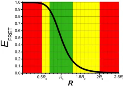
𝐸FRET = 𝑘FRET 𝑘FRET+𝑘DR+𝑘DNR= 𝑘FRET 𝑘FRET+𝜏D−1= 1 1+(𝑅/𝑅0)6= 𝑅06 𝑅06+𝑅6 (2.9)
As shown in Figure 2.3, FRET efficiency is most sensitive in a region between ca.0.5-2.0 𝑅0 (yellow) and exhibits very steep curve in a region between ca. 0.7-1.3 𝑅0 (green). FRET changes become extremely difficult to measure beyond this
region (red).
Figure 2.3. FRET efficiency as a function of the donor-acceptor distance (R) shows R-6 distance
dependence and leads to a steep curve around 𝑅0. (Reproduced from reference [3]. Copyright 2017 American Chemical Society)
12
FRET efficiency can also be calculated by the measurable PL properties including intensity (I), lifetime (τ), and quantum yield (Φ) using Equation 2.10:
𝐸FRET= 1 −𝐼DA 𝐼D = 1 − 𝜏DA 𝜏D = 1 − ΦDA ΦD (2.10)
where D is the donor in absence of the acceptor, and DA is the donor in presence of the acceptor.
2.1.2 FRET with multiple donors and/or acceptors
Nanoparticles (e.g., QDs) possess nontrivial surface areas, and usually can assemble multiple donors and acceptors on their surface. The D/A and A/D ratio can influence the FRET properties (sensitization and FRET efficiency). However, theoretical model for FRET system with multiple (m) donors and multiple (n) acceptors was only considered by a few studies.[4]–[7] According to Raicu’s theoretical model for FRET with m donors and/or n acceptors, FRET efficiency is solely dependent on the number of acceptors and the efficiency of a single D–A pair.[7] The relation between FRET efficiency and the number of acceptors also has been shown in an experimental study by Mattoussi’s group using n Cy3 acceptors around a QD donor,[8] which was the same as the theoretical model and can be descripted by the following Equation 2.11:
𝐸FRETmulti= 1 −𝐼DA(𝑛) 𝐼D = 1 − 𝜏DA(𝑛) 𝜏D = 1 − 𝛷DA(𝑛) ΦD = 𝑛𝑅06 𝑛𝑅06+𝑅6= 𝑛𝐸FRET 1+(𝑛−1)𝐸FRET (2.11)
An increasing FRET efficiency with an increasing number of n (acceptors per donor) is logical, because acceptors provide n possible FRET pathways to the excited donor, and therefore, the probability of de-exciting via FRET increases. For m donors around a QD acceptor, as mentioned above, the FRET efficiency does not change with an increasing number of m.[7] However, the probability of acceptor FRET-sensitization will increase with an increasing number of m and can be given by the following Equation 2.12.
𝑃A = 1 − (1 − 𝐸FRET)𝑚 = 1 − ( 𝑅
6
𝑅06+𝑅6)
𝑚
(2.12)
Based on a Monte Carlo simulation model,[4] Corry and co-workers considered the influence from different excitation intensities and designed a model to calculate
13
FRET efficiencies between m donors and n acceptors in complex geometries.[5],[6] It is significant because high excitation intensities may lead to many excited donors and/or acceptors, and as a result the already excited acceptors will be unavailable for FRET and decrease the FRET efficiency. This means that
Equation 2.11 is valid only for the FRET system with low excitation intensities,
in which all donors and acceptors have already gone back to ground states before the excitation. It is the same in the case of the probability of acceptor FRET-sensitization. So the Equation 2.12 is invalid for the FRET system with high excitation intensities or excited state of A is much longer than the one of D. However, Equation 2.11 and 2.12 is valid for cases in which the excited state lifetime of D is much longer than the one of A (e.g., lanthanide D and QD). When there are enough photons to excite several Tb (on the QD) and the QD, sequential FRET (all with the same FRET efficiency) from each Tb to the QD can occur due to the extremely long exited state lifetime of the Tb. For example: 10 Tb and the QD are excited, in the very beginning after the pulsed excitation (several 100 ns) the QD is excited and FRET cannot occur. After ca. 100 ns, the QD decays back to its ground state and can then become an acceptor (within these 100 ns, the probability of Tb de-excitation is small due to the ms lifetime). The QD will get FRET-sensitized by one Tb and then directly give away that energy (fluorescence within ns) and can be excited again. As the probability that the other 9 Tb are still excited is high due to the ms lifetime, the QD can be FRET sensitized again, and thus the FRET efficiency of this system will be constant but the probability of acceptor excitation increases with high intensities pulsed excitation. These FRET processes were studied in this thesis.
2.2 Quantum dots
Quantum dots (QDs) are luminescent inorganic semiconductor nanoparticles mainly composed of II-VI (CdS, CdSe, CdTe, ZnS, ZnSe, ZnTe), III-V (GaAs, GaN, GaP, InAs, InP), IV-VI (PbS, PbSe), I-VI(Ag2S, Ag2Se, Ag2Te), and I-III-VI (AgInS,
AgInSe, CuInS, CuInSe) groups of the periodic table, and also composed by alloyed structure, core/shell structure, and doped structure of these materials. Figure 2.4 represents the spectral range of emission for the most widely studied types of
14
semiconductor nanocrystals. The size of these nanoparticles that is usually between 1-10 nm in diameter (zero-dimensional nanomaterials) is smaller or close to their Exciton Bohr Radius. In 1982, Efros et al.[9] and Ekimov et al.[10] demonstrated that the ultra-small size of particle has a decisive effect on its optical and electrical properties. In 1983, Brus and colleagues at Bell Laboratories first reported colloidal QDs.[11] From then on, QD began to attract scientists' attention. In 1993, Bawendi et al. synthesized nearly monodisperse QDs in the high temperature organic solution.[12] Since the synthesized product was soluble in the organic phase, main application fields of QDs were focused on high density memory and photovoltaic equipment.[13],[14] Until 1998, Chan et al.[15] and Bruchez et
al.[16] pointed out that the water solubility and biocompatibility of QDs can be
solved by attaching thioglycolic acid to the surface of QDs or by coating with hydroxyl group functionalized SiO2 shell, which successfully established a
scientific foundation for the application in life science. The discussion below will focus on the optical properties (2.2.1) and surface functionalization (2.2.2) of QDs and examine how QD serves as FRET donor/acceptor/relay (2.2.3).
Figure 2.4. Spectral range of the photoluminescent emission for the most widely studied types of
semiconductor nanocrystals. (Reproduced from reference [17]. Copyright 2016 American Chemical Society)
2.2.1 Optical properties
QDs possess electronic properties that are intermediate between those of bulk semiconductors and discrete molecules. When a bulk semiconductor is excited by photons, an electron is promoted into the quasi-continuum conduction band (CB)
15
leaving a positively charged hole in the valence band (VB). The electron and the hole can bind to each other to form an exciton, and the distance in electron-hole pair is referred to as the exciton Bohr radius. Since the size of QDs is on the same order as the size of the exciton Bohr radius, when an exciton is created, the density of electronic states is not enough to form complete band structures and quantization of the energy levels can be observed at the band edges. The spatial confinement of excitons in QDs leads to a phenomenon known as quantum confinement, which has a direct effect on the boundaries of the bandgap. As illustrated in Figure 2.5, the inter-bandgap energy of QD can be tuned by the size of the nanoparticle. Due to the quantum confinement effect, the band gap of QD will increase as the particle radius decreases, and therefore a series of different emission wavelengths from the ultraviolet (UV) to the near-infrared (NIR) region can be obtained.[18]
From the perspective of fluorescent labeling, QDs possess many desirable photophysical properties.[19] (i) Broad and continuous absorption spectrum allows free selection of excitation wavelength. (ii) Both high molar absorption coefficient (105–106 M–1 cm–1 at first excitonic absorption peak, increasing toward UV
wavelengths) and quantum yields (up to 100%) lead to high brightness, which is essential for single particle tracking. (iii) Narrow, size-dependent, and symmetric emission spectra spanning from UV to NIR region are ideal for multi-color experiment. Generally, high quality and monodisperse QDs yield emission profiles with (full-width at half-maximum) FWHM which are typically in the range of 25-35 nm. It has been reported high-quality core-shell CdSe/CdS QDs with narrow emission line widths (FWHM ~20 nm) can be achieved through a slow growth rate of the shell.[20] (iv) Large effective Stokes shifts are efficient separations of the excitation and emission lights. (v) Remarkable photostability (strong resistance to photobleaching and chemical degradation) provides powerful support for long-term real-time bioimaging. (vi) High multiphoton action cross sections allow excitation with NIR light to have deeper tissue penetration and decrease autofluorescence from the biological matrix. It has been reported high-resolution in vitro and in vivo imaging can be achieved by combining three-photon excitation of ZnS nanocrystals and visible emission from Mn2+ dopants.[21]
16
Figure 2.5. Top: Cartoon, photograph, and PL spectra illustrating progressive color changes of
CdSe/ZnS QDs with increasing nanocrystal size. Bottom: Qualitative changes in QD energy levels with increasing nanocrystal size. Eg represent the bandgaps energies. Continuous conduction band
(CB) and valence band (VB) of bulk semiconductor shown as comparison. (Reproduced from reference [18]. Copyright 2011 American Chemical Society)
2.2.2 Surface functionalization
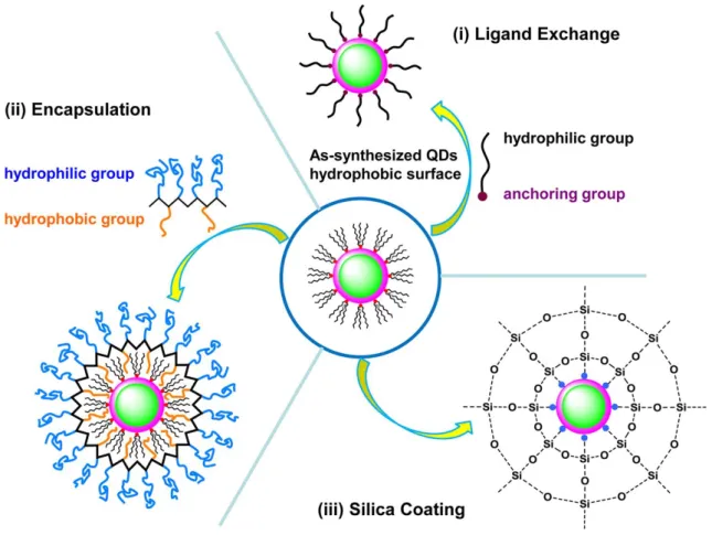
The surface functionalization of QD is a major issue for biomedical applications because most of high quality QDs are synthesized using hydrophobic surface ligands at high temperatures, therefore, as-prepared QDs are not directly soluble in aqueous media. For the purposes of making them stable in aqueous solution, as illustrated in Figure 2.6, there are mainly three different strategies: (i) ligand exchange, (ii) encapsulation, and (iii) silica coating.
Ligand exchange is the strategy by which the original hydrophobic surface ligands on the QD surface are replaced with hydrophilic ligands. Essentially these hydrophilic ligands consist of two functional components: the anchoring group(s)
17
and hydrophilic group(s). Thiol based molecules (mercaptoacetic acid (MAA),[22]– [24] mercaptopropionic acid (MPA),[25]–[27] mercaptoundecanoic acid (MUA),[28],[29] and dihydrolipoic acid (DHLA)[30]) are the most frequently used ligands due to their reasonably strong affinity for Cd and Zn, which are the most common metals on the surface of QD. However, the colloidal stability of QD coated with these ligands relies on deprotonation in of the carboxyl groups, limiting the usable pH range of QD. In order to solve the poor colloidal stability of thiol ligands, the thiol ligands were modified with poly (ethylene glycol) (PEG) to expand the usable pH range of QD.[31],[32] It has been reported that PEG-appended DHLA derivatives have been developed to enhance colloidal stability across a pH range from weakly acidic to strongly basic aqueous media.[33]–[35] The advantage of ligand exchange is that QD with small hydrodynamic diameter can be prepared, which is essential for FRET based biosensing applications.
Figure 2.6. Schematic overview of different strategies for surface functionalization of QD: (i)
ligand exchange, (ii) encapsulation, or (iii) silica coating chemistries. The center represents an as-synthesized QD in organic solvent with its hydrophobic surface of organic ligands. (Reproduced from reference [3]. Copyright 2017 American Chemical Society)
18
Encapsulation is a strategy by which to incorporate the QD with extraneous amphiphilic molecules via hydrophobic interactions. Surfactants such as phospholipids and amphiphilic polymers are commonly used amphiphilic ligands. In 2002, Dubertret et al. encapsulated individual QD in micelles and demonstrated them for both in vitro and in vivo imaging.[36] Since these encapsulation techniques do not modify the original ligand on the QD surface and prevent water interacting with this surface, QD almost preserve their original QY after encapsulation. However, this strategy often results in large hydrodynamic diameter, which is not optimal for FRET applications.
Silica coating is a method by which to form nucleation sites on the surface through ligand exchange using (3-mercaptopropyl) trimethoxysilane, followed by further shell growth with silane molecules such as tetraethoxysilane via hydrolysis and condensation,[37],[38] or a water-in-oil reverse microemulsion method.[39]–[41] The silica shell is quite robust and makes QD highly stable. Moreover, the silica shell is nontoxic and can be easier to functionalize with bioconjugation reagents. Despite significant advances in uniformity and size control of silica coating, the silica shell is still relatively thick compared to materials prepared with ligand exchange methods. Even so, there are fewer energy transfer and bioimaging studies by using silica shell coated QD.[42],[43] Recently, we developed lanthanide complex doped QD/SiO2 system and demonstrated them for FRET based living cell
barcoding.[44] We assembled the Tb-Lumi4 or Eu-1 on the QD surface with different thickness of silica shell (6 nm and 12 nm), and observed strong FRET signals due to large Förster distance (up to 12.2 nm) of Ln-QD FRET pairs.
2.2.3 QD as FRET donor/acceptor/relay
QD as FRET donor
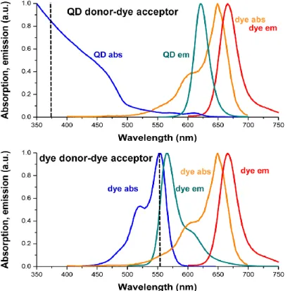
QDs can act as FRET donor, acceptor or relay. Most often, QDs are used as FRET donor due to their unique photophysical properties. As illustrated in Figure 2.7, compared with organic dye donors, the broad absorption spectra of QD donors can be excited in the blue/UV range, hundreds of nanometers from their emission maximum. This property leads to significant minimization of direct acceptor excitation and can enhance the FRET sensitivity. QD donors can be regarded as
19
nanoantenna due to their high extinction coefficients (>107 M-1 cm-1), which
increase sensitivity of FRET assay. The emission spectra of QDs are quite narrow and symmetrical, which means the donor emission does not leak into the acceptor detection channel. The surface area of QDs can assemble several acceptors around a single donor, which can allow “tuning” of FRET efficiency.
Figure 2.7. Comparative absorption and emission spectra of a hypothetical QD donor-dye acceptor (top) and dye donor-dye acceptor (bottom) FRET pair illustrating the photophysical differences
between a QD donor and a dye donor (black dotted line: putative excitation lines). (Reproduced from reference [3]. Copyright 2017 American Chemical Society)
In 2001, Willard et al. demonstrated QD donor based FRET to a dye-labeled biomolecule.[36] They conjugated a biotinylated bovine serum albumin (BSA) onto the QD surface, then mixed with dye-labeled streptavidin (dye-sAv) and observed a QD emission quenching with a dye emission increasing. In 2003, Patolsky et al. used DNA-based QD FRET to follow the dynamics of DNA replication on the QD.[45] They incorporated dye-labeled nucleotides into a nascent strand hybridized to the thiolated-DNA on the QD surface using a polymerase, and observed the spectroscopic signature of FRET after replication. The same year, Medintz et al. demonstrated protein-based QD FRET sensor using dye-labeled cyclodextrin binding to surface immobilized labeled or unlabeled maltose-binding
20
proteins (MBPs).[46] They used the MBP terminal His6-tag to conjugate proteins on the QD surface directly, which allow to precisely control the number and orientation of MBP. The number of QDs as FRET donor-based sensors has increased considerably since these early contributions. In particular, we are interested in QD donor-to-multiple dyes acceptors based FRET mechanism and their application. The studies about this system are listed in Table 2.1, which open the opportunity to use this system for fabricating desired photophysical properties for biosensing applications.
Table 2.1. QD as donor based multiple (n) acceptors FRET system.
Acceptors n Donors Application Mechanism
investigated Ref. QSY9, (Cy3, Cy3.5) 0~10 QD 530 / yes [46] Cy3 0~10 QD510, 530, 555 / yes [8] biot-Au NPs
(2~3 nm) ~9 (rod shape) sAv-QDs detection for avidin no [47] Rhodamine
Red-X, 0~48 QD545 extracellular matrix metalloproteinases (MMPs) activity in normal and cancerous
breast cells
no [48]
mOrange, mOrange M163K
15.7 and 16.5 QD 520 sensing intracellular
pH no [49]
EYFP, Atto647 0~18 QD / yes [50]
(A555, A647) (0,0)~(7,7) QD multiplexed protease
sensing yes [51]
Cy3-Cy3.5-Cy5- Cy5.5 1~8 QD525 / yes [52]
A555/A647 0~16 QD, A488 detection of the activity of nanomolar concentrations of
trypsin
yes [53]
(A555, A647) (0,0)~(7,7)
Green-emitting QD tracking the activity of trypsin and chymotrypsin
no [54]
(A555, A647) (0,0)~(12,18) QD520b,
QD525a / yes [55]
A610 or A633.
A555 or A647 0~30 530a, 540a, QD 525, 550, 575, 600, 650 / yes [56] (A555, Cy3.5 or At594, A647.)(L,M,N) L = 0, 2, 5, 8 (or L = 0, 3, 6, 9); M = 0, 2, 5, 8; N = 0, 2, 5, 8. QD quantitative tracking the proteolytic activities of trypsin, chymotrypsin, and enterokinase yes [57]
21 QD as FRET acceptor
In 2005, Clapp et al. studied dye-to-QD configuration and found no evidence for FRET with both steady state and time-resolved spectroscopy, even when the dye/QD ratio was increased up to 10.[58] They assumed that the direct QD excitation and excited-state lifetime difference should be responsible for this result. When organic dyes are excited, QDs are always directly excited at the same time due to their broad absorption spectra. Moreover, the relatively long excited-state lifetime of a QD (usually tens to hundreds of ns) compared to that of a typical organic dye (usually a few ns) leads to a very high probability that the dye will decay back to its ground state before the QD and therefore they cannot effectively serve as acceptors for a proximal excited dye.[59] They tested a Ru-based dye as donor (with several hundreds of ns lifetime) and observed significant lifetime quenching in the presence of a QD acceptor. This was the first indicator that long excited-state lifetime donors may unlock QD acceptor based FRET.
Although dye-to-QD based FRET configurations are generally unfavorable, QDs acceptor-based FRET has gradually been established using some non-traditional donors such as lanthanide complexes, chemiluminesent and bioluminescent molecules, and upconverting NPs (UCNPs).[59] The main issue of QDs as FRET acceptors is their broad and intense absorption, which means there are efficient excitation at all wavelengths shorter than their emission wavelength. In order to inhibit or decrease direct excitation of the QDs, there are three different strategies: (i) Lanthanide complexes usually possess a much longer excited-state lifetime compared to that of QDs, which can be measured by time-gated detection void of contribution of directly excited QDs. Hildebrandt and Charbonniere et al. demonstrated clear evidence for QDs to be used as FRET acceptors by combining them with Tb and Eu-complex donors.[60],[61] Although such lanthanides complex need to be excited in the UV range, which leads to more efficient excitation of QDs, the 105 times longer excited state lifetimes of the lanthanide donors proved to be
the key to unlocking QD acceptor based FRET. Time-gated detection after a sufficient delay time after the pulsed excitation allowed efficient detection of both lanthanide donor FRET-quenching and QD acceptor FRET-sensitization. (ii) Bioluminescent and chemiluminesent molecules as donors do not require light
22
excitation. If bioluminescent or chemiluminescent molecules are used as donors in FRET, the phenomena are now referred to as bioluminescence or chemiluminescence resonance energy transfer (BRET or CRET), respectively. In 2006, Rao et al. demonstrated QDs acceptor-based BRET. They showed that mutagenically optimized Rluc and QDs can be used as BRET donor-acceptor for multicolor imaging in vitro and in deep tissues in living mice.[62] In the same year, Ren et al. demonstrated an efficient CRET between luminol and QDs and showed potential application of multiple QDs acceptors with different color to multiplex analysis.[63] (iii) UCNP with higher energy visible PL can be excited using low energy NIR by sequential absorption of two or more photons. Therefore, direct QD excitation can also be avoided by using upconverting NPs as donors. It should be noted that FRET between UCNPs and QDs is not the most advantageous situation since the NPs usually possess relatively large size as compared to the usual FRET range of ca. 1 to 10 nm. Thus, in UCNP-to-QD FRET, only the lanthanide ions close to the surface can participate in FRET to the QD, whereas the ions close to the center of the UCNP usually remain unquenched.[64] In order to generate efficient FRET, it is necessary to design UPNCs with efficient surface-emitting lanthanide ions.
QD as FRET relay
QDs can serve as relay. In this case, the QD is used simultaneously as a donor and an acceptor, and can transfer energy provided by an initial donors to an acceptor. The advantage of QD as relay is that the color multiplexing can be achieved with a single QD. Figure 2.8 presents a full FRET relay cycle (e.g., mTb-QD-nA647) after a pulsed excitation. Both Tb and QD can be excited by pulsed UV light directly, whereas the A647 (assuming no direct excitation) remains in its ground state. In this situation, FRET2 (QD-to-A647) occurs and followed by A647 PL emission, while the FRET1 is forbidden. Then Tb still remains in excited state due to the long lifetime (~ms), in which the QD and A647 decay to their ground states. FRET1 (Tb-to-QD) will then occur followed by another FRET2 (FRET-sensitized QD to A647). Such kind of QD as relay based FRET systems have already been developed for enzymatic and hybridization assay or for the design of molecular logic gates. [65]–[68] In this thesis, we are interested the mechanism and application
23
of QD as relay based system, and previous studies about these systems are listed in Table 2.2.
Figure 2.8. (a) Schematic presentation of FRET (arrows) and radiative (flashes) transitions and
excited and ground state situations for a full FRET relay cycle after pulsed excitation. Steady-state (red) and time-gated (green, 55 μs) PL spectra of (b) pure QDs, (c) mTb-QD (time-gated FRET1 from Tb to QD), (d) nA647-QD (steady-state FRET2 from QD to A647), and (e) mTb-QD-nA647 (FRET relay).The black spectra show scaling of the steady-state PL spectrum to fit the time-gated PL spectrum. (Adapted from reference [3],[65]. Copyright 2017 American Chemical Society)
Table 2.2. QD as relay based multiple (m) donors and multiple (n) acceptors systems.
Acceptor n Donor m Application Mechanism
investigated Ref.
IRD700 / PDFD(polymer),
QD615 / detection of DNA hybridization yes [69] A647 0~15 Tb 0~20 monitoring protease
activity and nucleic acid hybridization
yes [65]
A647 0~5 Tb 0~10 multiplexed
protease sensing no [66] A647 0~25 Tb 0~25 complex logic
functions yes [67] A555/Cy3/A594 0~8 Ru-phen 0~12 detection of the
proteolytic activity of trypsin
yes [70]
A647 0~20 Tb 0~45 sensitive intra- and extracellular
fluorescence imaging
24
2.3 Luminescent lanthanides
Lanthanides are a series of 15 metal elements located at the sixth period and IIIB group in the periodic table, ranging from lanthanum to lutetium, with the electronic configuration of [Xe]4f𝑛−15𝑑0−16s2(n = 1−15), and are also referred as
the f-block elements. Trivalent lanthanide ions (Ln3+) are the most stable oxidation
state of lanthanide cations, except for Ce4+, Tb4+, and Yb2+, for which the f orbitals
are empty, half-, or full-occupied, respectively.[71] Due to specific electronic configurations, Ln show similar chemical properties. Ln3+ ions possess intrinsic
luminescence that originates from f−f electronic transitions, the 4f orbitals do not directly participate in chemical bonding due to shielding by the 5s and 5p orbitals, which minimizes the influence of external ligand fields, leading to sharp-band emissions.[72] Figure 2.9 show the ground and excited states of the Ln3+ ions,
where radiative transition between the energy levels occurs to give rise to luminescent lanthanide ions. As it can be observed for the Ln3+ ions on the
periphery (Ce3+, Pr3+, Nd3+, Pm3+, Ho3+, Er3+, Tm3+, and Yb3+), the energy gaps are
relatively small between adjacent levels, while the central metals (Sm3+, Eu3+,
Gd3+, Tb3+, Dy3+) exhibit larger energy gaps. As a result, f-f emission lines cover
the entire spectrum from UV (Gd3+) to visible (e.g., Pr3+, Sm3+, Eu3+, Tb3+) and NIR
(e.g., Pr3+, Nd3+, Er3+, Yb3+).[73] In addition, Ln3+ ions possess significant
paramagnetic properties due to unpaired electrons in 4f orbitals (except La3+ and
Lu3+). Unlike their chemical properties, the magnetic moments and magnetic
susceptibilities of Ln3+ differ dramatically along the series.[74]
The studies on lanthanide elements date back to the 18th century. With the development of lanthanide chemistry for more than two centuries, these elements have found a wealth of applications, ranging from high-tech products to health and medical utilization.[75],[76] Particularly, there has been a steady increase in the theoretical and experimental studies of luminescent lanthanide complex and lanthanide nanoparticle over the past decade, principally due to an increasing demand for photoluminescence and related applications, including electronic
25
display, document security, optical data storage, biological labeling, and imaging.[73],[77]–[82] The discussion below will review the luminescence mechanism and design of luminescent lanthanide complexes (LLCs) (2.3.1) and upconverting nanoparticle (UCNP) (2.3.2), and examine how lanthanide serves as FRET donor (2.3.3).
Figure 2.9. A summary of ground and excited energy levels of Ln3+ ions series. (Reproduced from
reference [72]. Copyright 2009 American Chemical Society)
2.3.1 Luminescent lanthanide complexes and nanoparticles
Luminescent lanthanide complexes (LLCs)
The unique luminescence properties of lanthanides come from transitions involving a redistribution of electrons within 4f orbitals because of the effective shielding by 6s and 5p orbitals. Since the transitions within 4f orbitals are in violation of the Laporte rule which states that electronic transitions that conserve parity, either symmetry or antisymmetry with respect to an inversion center are
26
forbidden, lanthanide ions display extremely long luminescent lifetimes and very small molar absorption coefficients (<10 M−1 cm−1).[83] In order to get more excited,
lanthanide ions usually require indirect excitation, which means the emissive states of lanthanides are populated through energy transfer from a sensitizing antenna. As illustrated in Figure 2.10 (a), the general architecture of luminescent lanthanide complexes (LLCs) consists of the Ln3+ center surrounded by a moiety
that coordinates the central ion (lanthanide ion carrier chelate) and equipped with a sensitizing chromophore moiety (antenna ligand). The chelate serves to prevent the release of free Ln3+ ions and to protect the Ln3+ ions from quenching from
vibrational energy dissipation by oscillators like O−H of water. For the antenna effect, a simplified Jablonski diagram shows the main energy migration pathways, the antenna harvests energy through high molar absorption to the ligand singlet excited state (S0 S1), and is generally assumed to first undergo intersystem
crossing to the triplet state (S1 T1), followed by population of excited states of
Ln3+ through energy transfer from T1 state of the ligand, and finally characteristic
luminescent emission from the Ln3+ ion. A large ligand-induced Stokes shift should
exist between ligand absorption and lanthanide emission in order to prevent back energy transfer which results in low quantum yields and short, temperature-dependent lifetimes.[73] Figure 2.10 (b) shows the transitions between the well-defined J-levels (degenerated from the electronic configuration based on Coulomb interaction and spin-orbit coupling) of Tb3+ and Eu3+.
The overall quantum yield, ΦLnL , of a lanthanide complex is given by Equation
2.13:
ΦLnL =𝐼Ln(E)
𝐼L(A) = sens ΦLn
Ln (2.13)
Where 𝐼Ln(E) is the number of photons emitted by the Ln metal ion, 𝐼L(A) is the
number of photons absorbed by the ligand, ΦLnLn is the intrinsic quantum yield of
the Ln metal ion, sens represents the sensitization efficiency.
Based on Equation 2.13, the ΦLnL can be improved by tuning the following two
factors: sens and ΦLnLn. A higher 𝜂
sens value can be achieved by the antenna ligand
with a higher intramolecular energy transfer rate, and a higher ΦLnLn can be
27
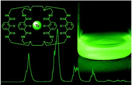
quenching effects of the aqueous matrix, and thus minimizes the non-radiative processes. Figure 2.11 represents the Tb complex (Lumi4-Tb) based on 2-hydroxyisophthalamide ligands we used in this thesis bearing maleimide functional groups and having a molar absorption coefficient of ca. 26000 M-1 cm-1
at 340 nm.
Figure 2.10. (a) Simplified Jablonski diagram for the antenna effect and the scheme of lanthanide
complexes (the Ln center surrounded by a chelate and equipped with a sensitizing antenna). (b) Commonly observed emission wavelengths of europium (red) and terbium (green) complexes.
(Reproduced from reference [84]. Copyright 2014 American Chemical Society)
Figure 2.11. Cage-like structure of the ligand for photon harvesting of the Lumi4-Tb complex used
28 Upconverting nanoparticles (UCNPs)
Luminescence usually follows Stokes’ law which states that emitted photons have a smaller energy than excitation photons. In 1966, Auzel suggested that energy transfer can take place between neighboring Ln3+ ions that are both in their excited
states by sequential energy transfer process, which is more efficient than excited-state absorption (or 2-step absorption). In this process, two (or more) low-energy photons are combined resulting in the emission of one higher-energy photon, known as upconversion emission.[86]
Figure 2.12. Principal UC mechanisms of Ln3+: (a) ESA, (b) ETU, and UC energy transfer
diagrams in (c) Yb3+−Er3+, (d) Yb3+−Ho3+, and (e) Yb3+−Tm3+ pairs, (f) CET, (g) EMU. (Reproduced
from reference [87]. Copyright 2015 American Chemical Society)
As illustrated in Figure 2.12, upconversion (UC) emissions of Ln3+ generally can
be divided into the following types of energy transfer pathways: excited-state absorption (ESA), energy transfer upconversion (ETU), cooperative transfer upconversion (CTU), and energy migration-mediated upconversion (EMU). In the case of ESA, excitation takes the form of the sequential absorption of two or more


![Figure 2.9. A summary of ground and excited energy levels of Ln 3+ ions series. (Reproduced from reference [72]](https://thumb-eu.123doks.com/thumbv2/123doknet/12875239.369605/38.892.108.785.272.801/figure-summary-ground-excited-energy-levels-reproduced-reference.webp)