HAL Id: tel-03014629
https://tel.archives-ouvertes.fr/tel-03014629
Submitted on 19 Nov 2020
HAL is a multi-disciplinary open access
archive for the deposit and dissemination of
sci-entific research documents, whether they are
pub-L’archive ouverte pluridisciplinaire HAL, est
destinée au dépôt et à la diffusion de documents
scientifiques de niveau recherche, publiés ou non,
Dielectric elastomer loudspeakers : models, experiments
and optimization
Emil Garnell
To cite this version:
Emil Garnell. Dielectric elastomer loudspeakers : models, experiments and optimization. Acoustics
[physics.class-ph]. Institut Polytechnique de Paris, 2020. English. �NNT : 2020IPPAE007�.
�tel-03014629�
NNT
:
2020IPP
AE007
Dielectric elastomer loudspeakers:
models, experiments and optimization
Th `ese de doctorat de l’Institut Polytechnique de Paris pr ´epar ´ee `a l’ ´Ecole nationale sup ´erieure de techniques avanc ´ees ´
Ecole doctorale n◦626 de l’Institut Polytechnique de Paris (ED IP Paris)
Sp ´ecialit ´e de doctorat : M ´ecanique des fluides et des solides, acoustique
Th `ese pr ´esent ´ee et soutenue `a Palaiseau, le 6 novembre 2020, par
E
MIL
G
ARNELL
Composition du Jury :
Herbert Shea
Professeur, EPFL (Soft Transducer Laboratory) Pr ´esident Jean-Franc¸ois De ¨u
Professeur, CNAM (LMSSC) Rapporteur
Morvan Ouisse
Professeur, ENSMM (FEMTO-ST) Rapporteur
St ´ephane Job
Maˆıtre de conf ´erences, Supm ´eca (Laboratoire Quartz) Examinateur Laurence Bodelot
Professeur assistant, ´Ecole polytechnique (LMS) Examinateur Olivier Doar ´e
Professeur, ENSTA Paris (IMSIA) Directeur de th `ese
Corinne Rouby
Maˆıtre de conf ´erences, ENSTA Paris (IMSIA) Co-encadrante Yoachim Horyn
Emil Garnell
Dielectric elastomer loudspeakers: models, experiments and optimization
November 6, 2020, Version: November 18, 2020 Reviewers: Jean-François Deü and Morvan Ouisse Supervisors: Olivier Doaré and Corinne Rouby ENSTA Paris, Institut Polytechnique de Paris IMSIA
828 boulevard des Maréchaux 91120 Palaiseau, France
Abstract
Dielectric elastomers are soft active materials capable of large deformations when acti-vated by a high voltage. They consist of a thin elastomer membrane (generally made of silicone or acrylic), sandwiched between compliant electrodes. The thickness of the assembly is about 100 microns. When a high voltage is applied between the electrodes, the membrane is squeezed between the electrodes, and increases in area by up to 100%.
This electromechanical conversion principle can be used to build loudspeakers. Proto-types have been developed and tested by several research groups, and models have been proposed to estimate their performance.
An intrinsic characteristic of dielectric elastomer loudspeakers is their multi-physic na-ture. Indeed, the actuation mechanism is itself a coupling between electrostatics and mechanics; the membrane is very thin and light, and couples therefore strongly with the surrounding air which is comparatively heavy; and finally the electrode electrical resistiv-ity induces a coupling between electrodynamics and mechanics.
The models proposed so far did not consider all of these couplings together, which lim-ited their use to qualitative estimations. In this thesis, a multi-physic model of dielectric elastomer loudspeakers is set-up, in order to optimize their acoustic performances, in terms of frequency response, radiated level, and directivity. The strong couplings be-tween electrostatics, membrane dynamics, acoustics and electrodynamics are studied with a finite element model in FreeFEM. This model is validated by dynamical and acous-tical measurements, and then used to improve the performances of the prototype, by working on several levels: optimization of the excitation, filtering, damping and con-trol.
Résumé
Les élastomères diélectriques sont des matériaux actifs souples capables de grandes déformations sous chargement électrique. Ils sont constitués d’une fine membrane d’élastomère (en général en silicone ou en acrylique), recouverte de chaque côté par des électrodes souples et étirables. L’ensemble a une épaisseur de l’ordre de 100 mi-crons. Lorsqu’une tension électrique est appliquée entre les électrodes, la membrane se comprime et sa surface peut augmenter de plus de 100%.
Ce principe de conversion électromécanique peut être utilisé pour réaliser des haut-parleurs. Des prototypes ont été développés par plusieurs groupes de recherche, et des modèles ont été proposés pour évaluer leurs performances.
Une caractéristique intrinsèque des haut-parleurs en élastomères diélectriques est leur nature multiphysique. En effet, le mécanisme d’actionnement est lui-même un couplage entre électrostatique et mécanique; la membrane est très fine et légère, et se couple ainsi fortement à l’acoustique car l’air est lourd par rapport à la membrane; et enfin la résistivité des électrodes engendre un couplage entre l’électro-dynamique et la mé-canique.
Les modèles proposés jusqu’alors ne considéraient pas l’ensemble de ces couplages, limitant leur utilisation à des estimations qualitatives. Dans cette thèse, un modèle multiphysique de haut-parleurs en élastomères diélectriques est mis en place, afin de permettre l’optimisation de leurs performances acoustiques, en terme de réponse en fréquence, niveau rayonné, et directivité. Les couplages forts entre électrostatique, dy-namique membranaire, acoustique, et électrodydy-namique sont étudiés à l’aide d’un mod-èle par éléments finis dans FreeFEM. Ce modmod-èle est validé par des comparaisons avec des mesures dynamiques et acoustiques, et ensuite utilisé pour améliorer les perfor-mances du prototype, en travaillant sur plusieurs plans : optimisation de l’excitation, fil-trage, amortissement, et contrôle.
List of publications
The work carried out during this PhD project resulted in several publications in peer-reviewed journals and conferences.
Articles in peer-reviewed journals
• Garnell, E., Rouby, C., & Doaré, O. (2019). Dynamics and sound radiation of a dielectric elastomer membrane. Journal of Sound and Vibration, 459, 114836. • Garnell, E., Doaré, O., & Rouby, C. (2020). Coupled vibro-acoustic modeling of a
dielectric elastomer loudspeaker. The Journal of the Acoustical Society of America, 147(3), 1812–1821.
• Garnell, E., Rouby, C., & Doaré, O. Resistivity-induced coupling between voltage distribution and vibrations in dielectric elastomers. Submitted in September 2020. • Garnell, E., Doaré, O., & Rouby, C. Model based adaptive filtering of dielectric
elas-tomer loudspeakers. Submitted in October 2020.
• Garnell, E., Aksoy, B., Rouby, C., Shea, H., & Doaré, O. Optimization of the elec-trode shape of dielectric elastomer actuators for dynamic applications. Submitted in November 2020.
Articles in conference proceedings
• Garnell, E., Doaré, O., & Rouby, C. (2019). Resonance modes for exterior vibro-acoustic problems, application to a dielectric elastomer loudspeaker. ICA 2019, Aachen.
• Garnell, E., Doaré, O., & Rouby, C. (2019). Modèle vibro-acoustique couplé d’un haut-parleur en élastomère diélectrique. CFM 2019, Brest.
• Garnell, E., Doaré, O., & Rouby, C. (2019). Dynamique et rayonnement acoustique d’une membrane d’élastomère diélectrique. CMSA 2019, Giens.
Other workshops and conferences
• Journées Jeunes Chercheurs en Acoustique et Bruit 2018, Le Mans. Industrial prize.
• Journées Jeunes Chercheurs en Acoustique et Bruit 2019, Femto-ST, Besançon. • Journées thématiques de la fédération francilienne de mécanique 2019: « Ondes
Acknowledgement
My greatest gratitude goes to my two supervisors, Olivier Doaré and Corinne Rouby, who came up with the idea of this thesis, and accompanied me during these three years. I am thankful for their trust and support, and the serene work atmosphere it led to. This helped me a lot in moving forward efficiently, and enjoying going to work every day. I appreciated Corinne’s great attention and rigor which helped clarifying many points in particular before submitting articles, and Olivier’s physical sense, which always pointed out new possible directions for my work.
I would like to thank sincerely Morvan Ouisse and Jean-François Deü for their very careful reading of the manuscript, and the whole jury for the interesting and stimulating discus-sions during the defense, I wish I had some more time to investigate ideas which have been suggested !
I would like to thank all people I interacted with in the lab during these three years. I appreciated the technical support in manufacturing the prototypes, setting up the mea-surement tools, buying the needed materials and train tickets, and the useful advices of Nicolas Baudet, Lahcene Cherfa, Thierry Pichon, Nicolas Thurieau and Cécile Callo-Labbe.
The group of PhD students, post-docs and interns at the lab formed a great team to spend time with, both for working and socializing. Thanks to you all David, David, David, Romain, Aurore, Haiqin, Marine, Thomas, Till, Jeremy, Aurélien, Guillaume, Joar, Jonathan, Baptiste, Lisa !
A special thought for my office-mates Tommy, Nicolas, Robin and Elodie, who created both a good studious context, and great company for coffee breaks. Working remotely for several month made me realize how important this is. I will also miss the lunch breaks running with Robin and Ludo, or climbing with Mathilde.
The doors of the senior researchers offices were always opened, and made it natural to come and ask for an advice. I am grateful to Benjamin Cotté, Cyril Touzé, Jean Bois-son, Jean-François Semblat, Romain Monchaux, Fabien Szmytka, Luc Pastur, for being available when I came knocking on the door. I would also like to thank Eliane Bécache, Claude Stolz, Marc Bonnet and Stéphane Job for helpful discussions.
After two years trying to manufacture reliable prototypes in the lab at IMSIA, I realized it could be efficient to collaborate with teams who are specialized in handling soft ma-terials. I contacted Prof. Herbert Shea, from the Soft Transducer Laboratory at the EPFL, who kindly offered me to spend a month in his lab to benefit from the group’s extensive manufacturing knowledge. I would therefore like to cheerfully thank the whole team who welcomed me warmly, Herbert, Bekir, Fabio, Sylvain, Vito, Edouard, Ronan, Djen and Giulio.
I ended up writing my thesis during the lock-down due to the Covid-19, and I would like to thank Gerard and Michelle Miquel for lending us their country house, where I could work efficiently in a calm natural environment.
Finally I’m grateful to my parents and family for their long term support in my studies, and to Faustine for stimulating my life during this whole period.
Contents
Main variables 1
1. Introduction 3
1.1. General context . . . 3
1.2. A short history of dielectric elastomers . . . 4
1.3. Dielectric elastomer loudspeakers . . . 5
1.3.1. Founding work . . . 5
1.3.2. First models and dynamic experiments . . . 7
1.3.3. More recent work . . . 8
1.4. Related work on dielectric elastomers . . . 10
1.4.1. Non-linear dynamics . . . 10
1.4.2. Viscosity . . . 11
1.5. Goals of the thesis . . . 12
1.6. Organization of the thesis . . . 14
2. Model of a DE loudspeaker 17 2.1. Overview of the modelling procedure . . . 17
2.2. Electromechanical coupling . . . 18
2.2.1. Literature review . . . 18
2.2.2. Theory . . . 22
2.3. Hyper-elastic membrane mechanics . . . 25
2.3.1. Literature review . . . 25
2.3.2. Theory . . . 25
2.4. Electrical model of the dielectric elastomer membrane . . . 27
2.4.1. Literature review . . . 27 2.4.2. Theory . . . 28 2.5. Acoustic radiation . . . 30 2.5.1. Literature review . . . 30 2.5.2. Theory . . . 32 2.6. Numerical procedure . . . 36
2.6.1. Set of coupled equations . . . 36
2.6.2. Static deformation . . . 37
2.6.3. Linear dynamics . . . 38
2.7. Conclusion . . . 44
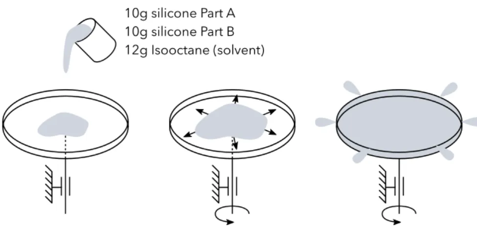
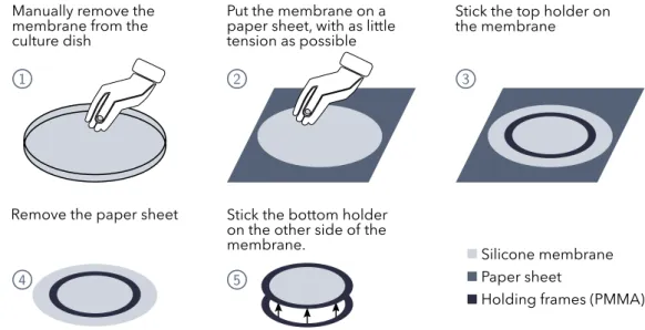
3. Experimental setup 45 3.1. Fabrication process . . . 45
3.1.1. Fabrication of the membranes . . . 45
3.1.2. Applying soft conductive electrodes . . . 49
3.1.3. Design of the electrode connections . . . 50
3.3. Identification of the material parameters . . . 55
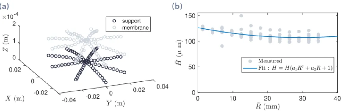
3.3.1. Hyper-elastic parameters . . . 55
3.3.2. Membrane thickness . . . 59
3.4. DE loudspeaker characterization procedure . . . 62
3.4.1. Overview . . . 62
3.4.2. Static deformation . . . 62
3.4.3. Impedance measurements . . . 62
3.4.4. Modal analysis and membrane dynamics measurements . . . 63
3.4.5. Acoustic radiation . . . 65
3.5. Conclusion . . . 65
4. Comparison of experimental and numerical results 67 4.1. Parameters of the prototype . . . 67
4.2. Static deformation . . . 67
4.2.1. Without applied voltage . . . 67
4.2.2. With applied voltage . . . 69
4.3. Membrane dynamics . . . 73 4.3.1. Free response . . . 73 4.3.2. Forced response . . . 76 4.4. Acoustic radiation . . . 79 4.4.1. Pressure on axis . . . 79 4.4.2. Directivity . . . 82 4.4.3. Harmonic distortion . . . 82
4.5. Demonstration of the multi-physics nature of the studied device . . . 83
4.5.1. Influence of the cavity stiffness . . . 84
4.5.2. Influence of the vibroacoustic coupling . . . 84
4.6. Conclusion . . . 85
5. Optimization 87 5.1. Static analysis . . . 87
5.1.1. Limits of dielectric elastomer membranes . . . 87
5.1.2. Optimal parameters for low frequency behavior . . . 89
5.1.3. Acoustic radiation with the optimal parameters . . . 91
5.1.4. Conclusion . . . 93
5.2. Optimization of the electrode shape . . . 93
5.2.1. Introduction . . . 93
5.2.2. Definition of the optimization problem . . . 94
5.2.3. Objective functions . . . 95 5.2.4. Optimization procedure . . . 97 5.2.5. Results . . . 98 5.2.6. Experimental investigation . . . 101 5.2.7. Conclusion . . . 103 5.3. Acoustic damping . . . 104 5.3.1. Theory . . . 104 5.3.2. Results . . . 106 5.3.3. Conclusion . . . 108
5.4. Control and filtering solutions . . . 108
5.4.2. Description of the studied system . . . 109
5.4.3. Theory of the control strategy . . . 109
5.4.4. Results . . . 111 5.4.5. Conclusion . . . 117 5.5. Conclusion . . . 118 6. Resistive effects 119 6.1. Literature review . . . 119 6.1.1. Lumped models . . . 119
6.1.2. Transmission line models . . . 120
6.1.3. Goal of the present work . . . 121
6.2. Theory . . . 121
6.2.1. Description of the studied system . . . 122
6.2.2. Transmission line model . . . 122
6.2.3. Model based on Maxwell’s equations . . . 124
6.2.4. Comparison of transmission line and Maxwell models . . . 131
6.2.5. Linearized coupled equations . . . 131
6.3. Application . . . 131 6.3.1. Coupled equations . . . 132 6.3.2. Experimental setup . . . 133 6.4. Results . . . 135 6.4.1. Membrane dynamics . . . 136 6.4.2. Impedance . . . 136
6.4.3. Voltage on the membrane . . . 138
6.5. Conclusion . . . 140
7. Conclusion 143 7.1. Summary of the main results . . . 143
7.2. Perspectives . . . 144
7.2.1. Model improvement . . . 144
7.2.2. Optimization . . . 144
Bibliography 147
Appendix
155
A. Constitutive equations of dielectric elastomers 157 B. Linearized weak forms 161 B.1. Static deformation . . . 161B.1.1. Solving step one . . . 161
B.1.2. Solving step two . . . 163
B.2. Dynamics . . . 164
C. Validation of the axisymmetric perfectly matched layers implementation 167 C.1. Description of the studied system . . . 167
C.2. Theory . . . 168
C.2.1. Weak form of the governing equation . . . 168
C.2.3. Pressure computation using the Rayleigh integral . . . 169
C.3. Results . . . 169
C.3.1. Frequency range of interest . . . 170
C.3.2. Mesh . . . 170
C.3.3. Convergence analysis . . . 170
C.4. Conclusion . . . 171
D. Validation of modal methods for exterior vibroacoustic problems 173 D.1. Description of the studied system . . . 173
D.2. Governing equations . . . 174
D.3. Numerical solving . . . 175
D.3.1. Finite element discretization . . . 175
D.3.2. Modal analysis . . . 175
D.4. Results . . . 177
D.4.1. Modal parameters . . . 178
D.4.2. Convergence of the modal summation . . . 180
Main variables
In the whole thesis, capital letters denote dimensional variables and small letters non-dimensional variables.
In the following list, the main dimensional variables are defined.
Variables with an overbar stand for variables defined in thereference configuration[see fig. 2.1].
Geometry
C = FTF Cauchy deformation tensor
-F = ∂X/∂ ¯X Displacement gradient
-n Normal unit vector
-u1, u2 In-plane unit vectors
-ˇ
H Membrane thickness at center in reference configuration m
λ1, λ2,λn Radial, ortho-radial and normal stretches
-Γ Electrode repartition function
-A Membrane radius in deformed configuration m
H Membrane thickness m R Radial coordinate m RE Electrode radius m V Volume m3 X Radial displacement m Y Vertical displacement m Z Vertical coordinate m General variables ϵ Permittivity F m−1 µ Shear modulus Pa
Ω Angular frequency rad s−1
ρf Density of air kg m−3
ρs Density of the membrane kg m−3
ρratio Ratio of electrode over membrane mass per unit area
-c = Cf/Cs Non-dimensional speed of sound
-Cf Speed of sound in air m s−1
Cs Speed of shear waves in the membrane m s−1
G Green function m−1
Jm Material parameter of Gent’s law
-m = ρfA/ρ¯ sHˇ Non-dimensional air density
-Electrical
D Electric displacement C m−2
E Electric field V m−1
P Polarization C m−2
ϱe Electrode resistivity Ω/□
U Voltage applied to the electrodes V
W Alternative excitation signal V2
Stresses
σ1 Radial stress Pa
σ2 Orth-radial stress Pa
P Pressure Pa
S1 Radial nominal stress Pa
S2 Orth-radial nominal stress Pa
Modal parameters
ψn Modeshape n
-kn Modal stiffness
-Introduction
1
In this chapter the scientific context of the thesis is presented, starting from a general overview of dielectric elastomer applications to the challenges for modelling, designing and manufacturing efficient dielectric elastomer loudspeakers. The goals of the thesis are then stated, and its structure is outlined.1.1 General context
We are today surrounded by loudspeakers, in our electronic devices, cars, buildings, etc. The vast majority are electro-dynamic loudspeakers, in which the sound-radiating mem-brane is moved by a coil oscillating inside a magnet. This principle has been developed by Rice and Kellogg in 1925 [92], and has been gradually improved since then.
For example, a high-frequency tweeter has been built in a larger woofer by Altec lansing in 1943, yielding a coaxial loudspeaker (Altec Lansing Model 604 Duplex radiator) that outperformed most of other loudspeakers at that time.
However, the physical principle remained the same for almost 100 years, and most inno-vations concerning loudspeakers concerned the enclosure, such as horn loudspeakers as the Klipschorn [65], or bass reflex which has been developed by Jensen in the 1940s. The reader is referred to [5] for a short history of the development of hi-fi loudspeakers. Even though electrodynamic loudspeakers have shown their ability to perform well in a wide range of applications, they still have a few drawbacks. The magnet which is re-quired to put into motion the voice coil is heavy, and also bulky. Strong magnets are made out of neodymium, which is costly. To obtain the necessary power, the magnet and voice coil need to be relatively thick, so manufacturing flat loudspeakers remains a challenge. Also, their distortion is rather large: the total harmonic distortion lies around 3% at low frequencies.
The last limitation (distortion) has been addressed by electro-static loudspeakers (ESLs), which have been patented by Janszen in 1953 [55]. They consist of a very thin plastic sheet placed between rigid and perforated metal electrodes (see fig. 1.1).
The main advantages of this driving mechanism is that the moving part is very light, and driven on its whole surface. The coupling with acoustics is therefore very strong, and the diaphragm is heavily damped. A very flat frequency response can be obtained, and dis-tortion is reduced by one order of magnitude compared to conventional electrodynamic drivers.
Varying electric field Metal grids
Plastic diaphragm coated with conductive material Static high
voltage
Fig. 1.1.Schematics of electrostatic loudspeakers. A thin plastic diaphragm is coated with con-ductive material, and placed between perforated metal plates. A high voltage static bias U0is applied to the diaphragm, and the electrodes are driven by the audio signal u(t).
ESLs have been commercialized from the late 1950s to nowadays, mostly for high-end loudspeakers. They are most of the time combined with a conventional woofer, because ESLs behave as acoustic dipoles, and can therefore not radiate properly at low frequen-cies.
The last type of loudspeakers which have obtained a commercial success are piezoelec-tric drivers. A piezoelecpiezoelec-tric crystal bends when a voltage is applied across its electrodes, and this mechanism can be used to radiate sound. Most piezoelectric drivers are used in applications where a high level is desired for a small size, and where cost is a ma-jor constraint. They are limited to high frequencies as only small displacements can be obtained.
In this thesis, we will investigate another type of loudspeakers, based on a different phys-ical principle. We will use an active material (dielectric elastomer) like piezoelectric crys-tals, but which is capable of much larger deformations (up to more than 100%), and should thus perform better at low frequencies.
Dielectric elastomer loudspeakers should also help address some limitations of elec-trodynamic loudspeakers, as it should be possible to obtain much lighter and flatter devices, by avoiding using a magnet.
The ultimate goal is to obtain small and flat loudspeakers, which can radiate at low fre-quencies, with limited distortion.
1.2 A short history of dielectric elastomers
Dielectric elastomer (DEs) are soft active materials, which have been studied for about 20 years now, after Pelrine et al. [87] showed that deformations of more than 100% in area can be achieved when a high voltage is applied.
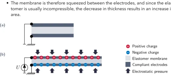
The working principle is the following, and is described in fig. 1.2:
• A soft elastomer membrane is coated on both sides with conductive and stretch-able electrodes.
• A high voltage is applied between the electrodes. This brings positive charges on one side of the membrane and negative charges on the other.
• The positive and negative charges are attracted to each other, and thus apply a normal pressure on the membrane surfaces.
• The membrane is therefore squeezed between the electrodes, and since the elas-tomer is usually incompressible, the decrease in thickness results in an increase in area.
+
+
+
+
+
+
+
+
+
_
_
_
_
_
_
_
_
_
+
+
_
_
Compliant electrodesElastomer membrane Electrostatic pressure+
_
Positive chargeNegative charge(a)
(b)
Fig. 1.2.Principle of dielectric elastomers.(a)Initial state, no voltage applied.(b)Deformed state, a voltage U is applied between the electrodes.
The research interest in DEs is high for several reasons.
First, DE actuators are soft, contrary to all motor-based solutions. This is of primary inter-est in robotics, where nature inspired robots become possible. Indeed, DEs reproduce the behavior of real muscles, as they have similar achievable stretch, energy density and stiffness.
Second, they offer combined actuation and position sensing. The deformation of the de-vice is related to its capacitance, which is easily measured during actuation. The deforma-tion can thus be monitored in real time. Self-sensing strategies can then be implemented to control the actuator in closed loop without any added sensor. Huge improvements of the actuator precision can be obtained.
DEs also work as energy harvesters, and can thus be used to build soft generators, that can be embedded in deformable structures, such as robots, cloths, gloves, etc.
It is beyond the scope of this introduction to provide a general review of the multiple possible applications of DEs, as it has been an active field of research for more than twenty years. For a broader view of the field, the reader is referred to the reviews by Anderson et al. [4], Rosset and Shea [99], and Gu et al. [40].
1.3 Dielectric elastomer loudspeakers
1.3.1 Founding work
The first published work on DE loudspeakers is the study by Heydt, Pelrine, Kornbluh and Mason from SRI International [43], in which inflated bubbles of silicone membrane coated with graphite powder are investigated. This configuration will be studied in the whole thesis, so the principle is described in fig. 1.3.
Compliant electrodes Elastomer membrane Electrostatic pressure
+
_
Positive chargeNegative charge (a) (b)+
+
+
+
+
+
+
_
_
_
_
_
_
_
Pressure Pressure Inflation pressure Fig. 1.3.Inflated DE membrane. (a)Initial configuration, the membrane is inflated over a closedcavity.(b)When a high voltage is applied, the membrane increases in area, and because of the the initial pressure, its moves outwards.
It was found in [43] that DEs have a high potential for making loudspeakers, because of their large achievable deformation, quick response and high energy density. A promis-ing sensitivity of 100 dB SPL/1W/1m was obtained, exceedpromis-ing the average sensitivity of standard electrodynamic loudspeakers (about 90 dB SPL/1W/1m). The main identified limitations are the high voltage required to actuate the speaker, as well as the large dis-tortion. However, it is indicated that the results were obtained without optimizing the design to improve those characteristics.
A similar device was further investigated in [46], where an array of inflated bubbles was considered. A radiated sound pressure level of more than 70 dB was obtained in the fre-quency range 1-20 kHz. It was also shown that shaping the excitation signal by a square root helps reducing a lot the major non-linearity coming from the square dependence of the electrostatic pressure on the applied voltage, reducing the total harmonic distortion to less than 5 % over the whole frequency range.
A patent of SRI international on the device studied in [43, 46] was published in 2002 [86].
An experimental study by the same authors in 2006 [45] investigated this time a sin-gle large inflated DE membrane, and not an array of small bubbles. The sound radia-tion properties were analysed, and it was found experimentally that a prototype with a positive inflation pressure (membrane inflated towards the outside) had a more omni-directional directivity than a membrane inflated with a negative pressure. General ideas of possible applications, where the directivity could be controlled by the inflation pres-sure, or by signal processing methods were mentioned but not studied.
The results of [45] have been patented in 2009 [44], where different biasing mechanisms were included in the patent, such as inflation pressure, foam backing, push-pull config-uration, etc.
1.3.2 First models and dynamic experiments
The pioneering work of Pelrine et al. raised a large interest in the research community, and several teams started investigating in more details the dynamics and sound radiation of DE membranes.
A substantial work has been carried out by Fox, Mockensturm and Goulbourne on the dynamics of inflated DE membranes. The purpose of their work is not loudspeakers, as they focused on the low frequency range.
Their first numerical study [81] focused on the transition between multiple state of equi-librium. The equations for the dynamics of axisymmetric DE membranes are derived, and used to analyse the static behavior of a spherical membrane, as well as the transient response of the membrane to a step input voltage.
The dynamics of an inflated DE membrane were then analysed experimentally in [32, 31] in the low frequency range (up to 200 Hz). A resonance was observed, and the influence of the excitation frequency on the membrane displacement was measured.
Their most complete study is [30], where the influence of the major design parameters (cavity volume, inflation pressure, bias voltage) on the membrane resonance frequencies has been experimentally analysed. However, no model was proposed to compute the forced dynamics of the membrane, so only experimental conclusions could be drawn. Among the early works it is worth mentioning the study by Dubois et al. [25], where a millimetric flat DE membrane was investigated. The electrostatic pressure created by the applied voltage decreases the tension in the membrane, which decreases its first resonance frequency. A decrease in frequency of 77 % is observed when the voltage is applied, and a simple model is derived to explain this decrease.
A similar study was performed by Hochradel et al. [47], but for an inflated membrane. The change in frequency due to the electric voltage was studied, as well as the dynamical and acoustical response of the membrane when actuated by an oscillating signal. A model has been developed, but only to analyse the influence of the static voltage on the first resonance frequency of the system.
Also, the work by Keplinger et al. published in Science is interesting, as it demonstrated the possibility to manufacture transparent loudspeakers using DEs. This is made pos-sible by the use of ionic hydrogels as electrodes, instead of the electronic conductors which are generally used (carbon or metal based). Inoic conductors are found to have a higher conductivity than electronic conductors, which is important for the high frequency efficiency of DE loudspeakers.
Transparent DE loudspeakers have also been studied by Yu et al. [122], where trans-parency is achieved by using carbon nanotube electrodes. The loudspeaker frequency response is measured, but the sound generation mechanism is unclear as the loud-speaker consists only in a stretched DE film. Without any biasing mechanism the DE membrane should move in plane, and thus does not radiate sound efficiently.
Transparent DE loudspeakers have also been demonstrated by Xu et al. [120], where graphene based electrodes are used.
The first model of the dynamics of an inflated DE membrane, that does not make the as-sumption that the membrane behaves like a one-degree-of-freedom system is the study by Zhu et al. [126]. The eigenmodes of an inflated membrane around a non-linear static equilibrium are computed, and the influence of the inflation pressure and bias voltage are analysed. This paper is also the first to compute the frequency-response functions of an inflated DE membrane, using time integration. Interesting non-linear phenomena are observed, such as sub- and super-harmonic resonances. However, the results presented in this study are purely numerical, and are not validated by experiments.
1.3.3 More recent work
DirectivityThe team of Maeda et al. carried out several studies on the use of inflated DE membranes as loudspeakers.
They investigated the directivity of a hemispherical membrane [51], showing that an al-most omni-directional directivity could be achieved in a hemisphere. A suggested po-tential application of DE loudspeakers is room impulse response measurements, where an omnidirectional point source is required. However, the maximum sound pressure level radiated by DE loudspeakers may limit this application.
This study was extended to the case of a spherical loudspeaker in [52], where the di-rectivity of an inflated VHB (commercial 3M acrylic tape) membrane is measured. The authors claim that they explained the observed directivity by membrane modeshapes measurements, but this part of the study suffers from methodological flaws.
Other biasing mechanisms
Other geometries based on different biasing mechanisms than the inflation have also been investigated.
Sugimoto et al. [107] used a rigid elastomer instead of the commonly used silicone or acrylic membranes. The rigidity of the elastomer allows the authors to avoid the use of a frame to hold the membrane. To convert the in-plane displacement to out-of-plane displacement, the DE is bent into a semi-cylindrical shape. The influence of the major de-sign parameters is investigated experimentally, but no model capable of computing the radiated pressure is provided. The sensitivity is also analysed, and found to lie around 70 dB/W/m, that is to say about 20 dB lower than standard loudspeakers.
The same team investigated the push-pull configuration suggested by Heydt et al. [44], in which two membranes are placed one apon another, with a rigid connector between them. When one membrane increases in area, the other decreases. They proposed a model to compute the fundamental resonance [106]. It is found that the push-pull configuration reduces the second harmonic distortion by 10 dB, the non-linearity of one membrane being compensated by the other.
(a) (b)
Fig. 1.4.From Rustighi et al. [102], c. Working principle of DE with perforated rigid electrodes. (a)Un-deformed configuration.(b)Deformed configuration, when an actuation voltage is applied.
A team at Darmstadt, Germany, developed another interesting concept for using DEs as loudspeakers [113, 59]. Contrary to most other studies, rigid electrodes are used. They are made or perforated metal plates, as shown in fig. 1.4. A stack of alternating elastomer and electrode layers is built. When a voltage is applied between the electrodes, the elastomer is squeezed and the excess material can move in the electrode holes. The whole stack is then compressed, and a normal displacement is obtained, so sound can be radiated. One of the main advantages of this geometry is that metal electrodes are used, which are thus very conductive. The high frequency response will not be limited by the electrical behavior of the system.
This acoustic actuator is then used for active noise control with promising results in dou-ble glazed windows [42].
A more in-depth experimental analysis of the sound radiation of the sandwich structure proposed in [59] is performed in [102]. The sound radiation properties of the flat perfo-rated plate loudspeaker are studied, including frequency response, directivity, and har-monic distortion. Sound radiation in the frequency range 1-15 kHz is demonstrated.
Coupling with acoustics
Few authors investigated the influence of the coupling between acoustics and mechan-ics on DE vibrations.
A first attempt is the work by Lassen, but the methodology and the results presented in [71] are doubtful and unreliable. The influence of acoustics is modelled by the plane wave impedance, which does not hold in the near field.
Another attempt in found in the paper by Chakravarty [16], but it is restricted to a flat membrane, and studies only the variation of the first resonance frequency when the var-ious design parameters are varied. The coupling with acoustics is taken into account by analytical formulas valid only for flat circular membranes. This is thus of little use to study inflated DE membranes.
Abbad et al. [1] studied both experimentally and numerically a tunable Helmholtz res-onator, in which one of the cavity walls is made of a stretched dielectric elastomer mem-brane. The membrane is flat, so a membrane model with uniform tension is used, and coupled to acoustics in a commercial finite element code.
In a different context, Rothemund et al. [100] from the Harvard group studied a trans-parent DE membrane for active noise control in ducts. The membrane is pre-stressed and placed in a duct, and a plane wave is sent on it to analyse the transmission loss. The membrane is also used as an actuator to implement active noise cancellation, leading to an improvement of 10 dB of the transmission loss. The interaction between acoustics and the membrane dynamics is taken into account, but in this case it is relatively simple since only plane waves propagate in the duct.
Improvement by signal processing
The team at Darmstadt recently investigated possible improvements of the frequency response and directivity of DE loudspeakers by means of digital signal processing [66]. A DE loudspeaker made of an array of inflated bubbles, such as described in [86] was studied. The audio signal is processed by a digital signal processor (DSP) before it is fed into the high voltage amplifier and the DE loudspeaker. This method is shown to enable great improvements of the frequency response, as well as of the total harmonic distortion.
Some of the main limitations of this method is that the response of the speaker needs to be precisely known to design correctly the filters. If the system response changes (aging, change of the inflation pressure), the filters become inappropriate.
1.4 Related work on dielectric elastomers
1.4.1 Non-linear dynamics
Due to their large deformations, DE are non-linear in nature. For accurate description of their properties, hyper-elastic material models are needed, and geometrical non-linearities must also be taken into account. What is more, the relation between the electrostatic pressure and the voltage is quadratic. Also, elastomer membranes often exhibit visco-elastic behavior, which may require non-linear visco-elastic models to be described. For all these reasons, there is a substantial literature on the non-linear dy-namics of DE actuators.
As noticed above, the effect of non-linearities on the dynamics was observed in the first studies on the use of DEs as loudspeakers [46] in the form of harmonic distortion of the radiated acoustic pressure.
The first study on the non-linear dynamics of DEs may be the paper by Zhu et al., who investigated the oscillations of a DE balloon using a 1-DOF model [125]. The frequency response is studied, and sub-harmonic, harmonic, as well as super-harmonic resonances are observed. Also, the oscillation amplitude may jump when the excitation frequency is varied.
This study was extended to multiple-DOF models in Zhu et al. [126], where an inflated dielectric membrane is analysed using time integration of non-linear membrane equa-tions.
Apart from the study by Zhu et al., most of the studies on non-linear dynamics of DEs focus on 1-DOF devices.
For example, Xu et al. showed that even for a simple DE slab undergoing uniform de-formation [116], complex dynamics are observed, in particular pulsating (modulated) responses when the system is excited with a sine electrical signal.
Cao et al. tried to design DE systems to observe strongly non-linear behaviors. A planar DE actuator which oscillates out of plane when a oscillating voltage is applied is studied in [14]. A 1-DOF model is set-up, including viscosity, and used to analyse the non-linear dynamics. A prototype is also built, and shown to exhibit sub-harmonic, harmonic, and super-harmonic responses.
A similar study but for a 1-DOF oscillator with two stable equilibrium positions was car-ried out by the same team [13]. The non linear dynamics of a bi-stable DE oscillator are studied, and various oscillation regimes are identified depending on the amplitude and frequency of the excitation.
This prototype was designed to reach the largest possible displacement at resonance, so a membrane designed for use as a loudspeaker may not vibrate in this strongly non-linear regime, and exhibit the same complex dynamics.
Some authors also started investigating control strategies to handle the non-linear dy-namics, such as Li et al. [72] who show that the non-linear dynamical response can be controlled using a PID and a feedback loop.
We listed above some interesting works on the non-linear dynamics of DE devices, which are more or less closely related to loudspeakers applications. It appears that most stud-ies either focus on 1-DOF systems where a physical understanding of the observed non-linear phenomena is possible, or demonstrate rich dynamic behaviors on more complex systems. To study and reduce the distortion of DE loudspeakers, there is more a need of models capable of predicting the weakly non-linear dynamic response over a large fre-quency range, than a need of models focusing on 1-DOF systems exhibiting a strongly non-linear behavior.
We therefore believe that setting-up multiple-DOF models of DE loudspeakers is the pri-mary step, first to study linear dynamics and then to compute the harmonic distortion. The non-linear dynamics could unfortunately not be studied for time reasons in this the-sis.
1.4.2 Viscosity
Two types of materials are commonly used to manufacture DE actuators: silicone and acrylic elastomers.
Acrylic (and especially the very commonly used 3M VHB) exhibits the most impressive electromechanical coupling, with the largest obtained static deformations and energy density.
However, VHB has a large viscosity, and typically creeps during several minutes when actuated. The effects of visco-elasticity on the dynamics have thus been studied by sev-eral research groups, and shown to affect the non-linear dynamics of DE devices [124, 17, 103, 50, 123].
Silicone elastomers on the other hand have a lower viscosity, and react faster [96]. The dynamics will thus be less influenced by visco-elastic effects in silicone elastomers than in acrylics.
Silicone is used in this thesis, and loss phenomena are taken into account by simple damping models, and not visco-elastic models. This choice will be justified by experi-mental analyses.
1.5 Goals of the thesis
The study of the literature on DE loudspeakers reveals that the field is currently in a state where most ideas and options on how to produce sound with these materials have been tested.
There are many studies that show that sound radiation of interesting level can be ob-tained in a rather large frequency range [45, 88, 102], that distortion can be reduced to acceptable values by signal processing methods [45, 66], and that the device can be made transparent by using specific types of electrodes [122, 63, 120].
However, there is still no commercially available DE loudspeaker. We believe several reasons explain this:
• DEs need high voltage to be actuated. This may be dangerous, and requires bulky high voltage amplifiers. This limitation is addressed by research teams working on the manufacturing processes, who aim at producing reliable thinner membranes and electrodes. One may hope that stacked DE actuators with low operation volt-ages should be available in the coming years.
• DE loudspeaker designs are non-linear in nature, which is in contradiction with the desired behavior of loudspeakers. The non-linear dynamics of DE devices are stud-ied by several research groups, and control strategies to limit the harmonic distor-tion start to appear.
• Most studies demonstrate the possibility to make loudspeakers out of DEs, but few try to optimise for real the system. We believe the reason why no real optimization is performed is that there are still modelling issues that are not addressed. The models used currently for DE loudspeakers allow to qualitatively explain the main characteristics, but are not predictive. To the author’s knowledge there is no study where a model is shown to be able to predict quantitatively the sound radiation properties of a DE loudspeaker.
Therefore, the goal of this thesis is to develop an accurate model of DE loudspeakers, that is capable of computing the acoustic and dynamic response of sufficiently precisely, so that it can be used for design purposes, for example to run optimization routines to improve the behavior of the loudspeaker.
Several difficulties are raised by this goal, the main being the multi-physics nature of DE membranes. Indeed, the excitation mechanism itself is a coupling between electrostat-ics and mechanelectrostat-ics. The DE membranes are usually so thin that the surrounding air must be considered as a heavy fluid, leading to strong vibroacoustic coupling. Also, due to the high electrode resistivity, the dispersion of electric charges on the electrodes takes time, and appears to be coupled to the membrane vibrations. This questions the validity of electrostatic models to describe the electrical part of the system.
Neglecting some of these couplings is perfectly acceptable for a phenomenological ap-proach, if the goal is to provide an understanding of the global behavior of DE loud-speakers. However, as soon as a predictive model is needed, these couplings need to be taken into account.
Predictive models have been developed for other DE devices, but not yet for loudspeak-ers. Models for loudspeakers typically require features that may not be useful for other uses. A large frequency range is studied, from a few hundred hertz to more than 10 kHz. This implies that the model will need multiple degrees of freedom, as many modes will contribute to the dynamics and sound radiation. There is a substantial literature on 1-DOF models for DE, but fewer studies using multiple-1-DOF models.
Also, loudspeakers should behave as linear systems. Even though non-linear models are useful to predict and reduce the distortion for example, we believe that many limita-tions of DE loudspeakers can be addressed by linear analyses. Therefore we will work here with linear models, which allow solving in the frequency domain, which saves a lot of computational time. Being able to compute quickly frequency-responses opens the path for automatic optimization of the design, as the loudspeaker models can be fed into optimization routines.
To summarize, the main objectives of the thesis are: • Develop a predictive model for DE loudspeakers.
• Use this model to optimize the parameters of the device, and investigate whether large improvements are achievable by properly choosing the appropriate values of the design parameters, or by setting up control strategies.
• Improve the modelling of DE devices in the high frequency range, where resistivity effects are important.
These objectives are in line with the conclusions of the recent review on DEs by Gu et al. [40], where the main challenges of the field are identified as:
• Accurate models to compute DE actuators dynamics are needed.
• Control strategies specifically designed for DE actuators should be developed. • Driving electronics designed for DE actuators should be designed, to cope with
1.6 Organization of the thesis
In this thesis, a single geometry is investigated, namely inflated DE loudspeakers. This configuration was chosen because it is the most widely studied in the literature [45, 126, 51, 66, 30], and because it also appears to be simple, and can thus be implemented in real situations. The studied device is presented fig. 1.5, and the reader should keep this geometry in mind as it will be used throughout the thesis.
Membrane Electrodes Aluminium tape Frames Connectors Pressurized cavity
Fig. 1.5.Schematics of the studied device.
The second chapter presents the developed model of DE loudspeakers. The different physics that must be taken into account are analysed one by one, and coupled together. The numerical method based on finite elements which is used to solve the coupled equa-tions is also presented.
In the third chapter, the experimental setup is introduced, including the manufacturing process of the membranes, the coating with soft electrodes, and the various measure-ment processes for static and dynamic analyses.
The fourth chapter presents the results of both the model and the experiments, in order to validate the model. Statics, dynamics and acoustics are validated successively. In the fifth chapter, the model is used to examine whether the DE loudspeakers can be improved, by making the right choices of the design parameters. Static analysis are first
carried out to enhance the low-frequency behavior, the electrode shape is then opti-mized to improve the frequency response, and digital signal processing methods are finally investigated to control the frequency response and the directivity.
The electrode resistivity effects on the electrodynamical loading, and the resulting cou-pling between electrodynamics and mechanics is finally investigated in chapter 6. This effect has little consequences on the acoustical behavior, and is therefore omitted in chapter 2 for clarity reasons. However, it may enable possible new self-sensing strate-gies.
Model of a DE
loudspeaker
2
In this chapter, the model that is developed to study inflated dielectric elas-tomer membranes is presented. First, an overview of the modelling pro-cedure describing the main steps is given to identify the different physics that will be taken into account. The second section derives the constitutive equations of dielectric elastomer membranes. The three following sections study one by one the main physics involved: membrane mechanics, acous-tics, and electrokinetics. Finally, the numerical procedure which is used to solve for all the steps is described.
2.1 Overview of the modelling procedure
Pre-stretch
Applied pressure Static voltage Dynamic excitation - Non-linear mechanics - Non-linear mechanics
- Electromechanical coupling
- Adiabatic gas evolution
- Linear membrane dynamics - Electromechanical coupling - Strong vibroacoustic coupling - Electrokinetics
step 1 step 2 step 3
reference
configuration configurationstatic
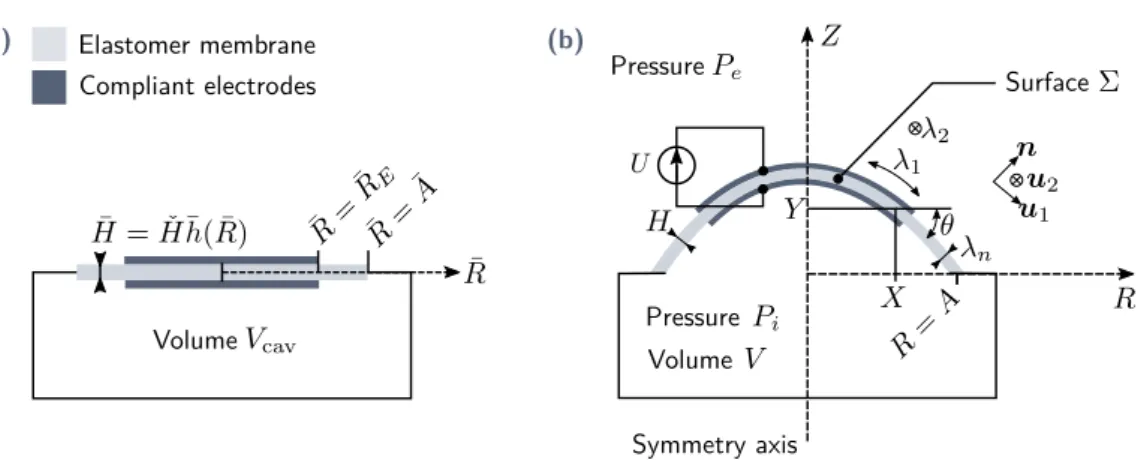
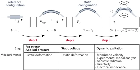
Fig. 2.1.Overview of the modelling procedure. Instep 1, the membrane is pre-stretched from radius ¯Ato radius A, and inflated with the applied pressure Papp. Instep 2, the cavity is closed, and a static voltage U0is applied. The volume and the pressure in the cavity change. Instep 3a dynamic excitation signal is superimposed to the static voltage. The membrane vibrates and couples to the surrounding air.
The modelling procedure is decomposed into the following steps [see fig. 2.1], which mimic the experimental procedure:
• step 1. The membrane is originally at rest in a reference state denoted hereafter as reference configuration. During step 1, the membrane is equi-biaxially
pre-stretched from the radius ¯A to the radius A, and inflated with the applied pres-sure Papp. In order to compute the resulting deformation, a hyper-elastic model is
used for the membrane. The non-linear static equilibrium is computed using the Newton-Raphson algorithm.
• step 2. The cavity is closed and contains a fixed quantity of air, whose thermody-namic evolution is supposed to be adiabatic. This is valid as long as the timescale of the mechanical dynamics is smaller than the timescale for thermal conduction. A static voltage U0is applied between the electrodes.
To compute the resulting equilibrium, the same non-linear model as instep 1is used, but this time including electromechanical coupling. The obtained equilib-rium is denoted thestatic configuration. In this configuration, the membrane co-ordinates are written (X0, Y0), and the pressure in the cavity P0. All variables that
refer to this configuration are written with the subscript zero.
• step 3. An alternating signal is superimposed to the static voltage U0. This signal
vibrates the membrane which radiates sound in the surrounding air.
The strong couplings between the membrane vibrations and acoustics must be taken into account to yield accurate results. Also, due to resistivity effects, the ef-fective voltage on the electrodes may differ from the applied voltage U . This will be taken into account by electrokinetics lumped models. Duringstep 3, only lin-ear vibrations are considered, and all quantities will be linlin-earized around thestatic configuration.
2.2 Electromechanical coupling
In this section, a model to describe the electromechanical coupling is derived, first in a general 3D case, and later simplified to membrane mechanics.
2.2.1 Literature review
Uniform deformation of flat DE membranes
The first works on DEs, by Pelrine et al. [87, 88] used simple models to describe the electromechanical coupling.
They model the DE device as a parallel plate capacitor, whose energy is written as:
E = Q2
2C =
Q2H
ϵS , (2.1)
where C is the capacitance, Q the electrical charge on the top electrode, ϵ the dielectric permittivity of the membrane, H the thickness of the capacitor and S its area. The change in energy due to a change of thickness and area can be expressed as:
dE = Q2
ϵSdH−
Q2H
Assuming that the elastomer is incompressible yields the following constraint between the thickness and the area:
dS
S =−
dH
H . (2.3)
Inserting this constraint in eq. (2.2) finally yields: dE = Q2
ϵSdH . (2.4)
The effective pressure that deforms the membrane is defined as:
σ = 1 S dE dH = Q2 ϵS2 . (2.5)
The charge on the electrodes can be related to the applied voltage by Gauss’s law, which gives:
σ = ϵU
2
H2 = ϵE
2, (2.6)
where U is the applied voltage, and E the electric field. Equation (2.6) defines the effec-tive electrostatic pressure, which is found to be twice the Maxwell pressure which equals
σMax = 1/2ϵE2. This doubling of the effective pressure is directly related to the
incom-pressibility constraint.
A more detailed look at the electric field and interaction between the electric charges gives a different interpretation of the electrostatic loading of the membrane. An inves-tigation of the pressure created by a distribution of electric charges was performed by Wissler and Mazza [115], who found that there is both a normal pressure σz = 1/2ϵE2 which is applied normal to the membrane surface, and a pressure in the membrane plane of value σr=−1/2ϵE2. The pressure in the membrane plane can be interpreted as the repulsion between charges of similar sign.
The comparison between these two points of view is shown in fig. 2.2.
(a) (b)
Equivalence for incompressible
materials
Fig. 2.2.Electrostatic loading of an axisymmetric DE membrane. (a)Point of view of Pelrine et al. [88]. (b)Force repartition obtained from the analysis of charge distributions [115]. The two points of view describe stress states which result in the same deformation for incom-pressible materials, as the distribution in(b)is obtained by superimposing the hydrostatic stress σ = 1/2ϵE2to the distribution of(a). The equivalence is valid for flat membranes.
Deformation of DE curved membranes
When the membrane is curved, the analysis of the charge distribution becomes a lit-tle more complicated, and is schematized in fig. 2.3. The surface charge on the outer
electrode will be lower than the surface charge on the inner electrode. This results in a different electrostatic pressure applied on the two electrodes.
(a)
Equivalence for incompressible
materials (b)
Fig. 2.3.Electrostatic stresses generated by charged electrodes on a curved DE membrane. κ1 and κ2are the curvatures in the radial and orthoradial directions respectively.(a)Pelrine’s point of view: double normal pressure. (b)Stress distribution found by analyzing the charge distribution.
Anticipating a little on the following, the equilibrium equations of an inflated axisymmet-ric hyper-elastic membrane read [2]:
∂σ1HR
∂R = σ2H , κ1Hσ1+ κ2Hσ2= P , (2.7)
where σ1is the radial stress (along u1) and σ2the ortho-radial stress (along u2), H the
membrane thickness, P the inflation pressure, R the radial coordinate. The jump condi-tion at the membrane border reads:
JHσ1K + Hts= 0, (2.8)
where tsis the surface stress applied on the membrane border in the direction nb[see fig. 2.3],JHσ1K = (Hσ1)in− (Hσ1)outis the jump of Hσ1across a discontinuity surface of
normal nb.
The stress state can be described in two different manners.
First description of the electromechanical coupling The total stresses read:
σ1= σ1m− 2σMax, σ2= σ2m− 2σMax, (2.9)
where σMax= 1/2ϵE2, and σ1mand σ2mare the mechanical parts of the principal stresses.
These expressions will be obtained rigorously in the following section, and are used here to explain fig. 2.3. The total set of equilibrium equations for the DE membrane comprises eqs. (2.7) to (2.9), and describes the stress state shown in fig. 2.3a.
Second description of the electromechanical coupling We define new stresses by: ˜
Inserting these expressions in the equilibrium equations (2.7) and (2.8) yields: κ1H ˜σ1+ κ2H ˜σ2= P + σMax(κ1H + κ2H) , (2.11a) ∂ ˜σ1HR ∂R + R ∂σMaxH ∂R = ˜σ2H , (2.11b) JH ˜σ1K + JHσMaxK + Hts= 0 . (2.11c)
If the thickness is uniform, the electrostatic pressure σMaxis uniform too, and the second
term in eq. (2.11b) vanishes. The set of equations (2.11) then corresponds exactly to the stresses described in fig. 2.3b. If the thickness is not uniform, the second equilibrium has one more term compared to eq. (2.7), that is related to the variation of the electrostatic stress along the radius.
This second description of the electrostatic coupling is easier to interpret in terms of electric charge distributions, but is way less practical to use for numerical calculations than the first description where only a normal electrostatic pressure is required.
Moreover, the first description of the electrostatic coupling comes out naturally from the analysis of DE membranes based on energy considerations, as it will be shown in section 2.2.2.
General models for non-uniform deformations
While the approach proposed by Pelrine et al. is valid to describe one-degree-of-freedom system, this method is harder to apply to deformable membranes undergoing non-uniform deformations.
A unifying theory of DEs has been proposed by Suo et al. [109, 108], where the coupled electromechanical equations are obtained starting from the definitions of work, electric charges, and force.
Another general approach to obtain coupled electromechanical equations derives from the work by Coleman and Noll [19], who proposed a framework based on thermodynam-ics to derive coupled multi-physthermodynam-ics constitutive relations. This framework was used to de-rive the constitutive equations for electromagnetism, mechanics, and electromagnetism coupled to mechanics by Kovetz [69]. Edmiston and Steigmann [26], and Dorfmann and Ogden [24] applied it successfully to DEs.
A review of the different modelling approaches for non-linear electromechanics has been written by Bustamante et al. [12].
In this thesis, we will use the approach proposed by Kovetz [69], and its application to DEs by Edmiston and Steigmann [26] as it appears to be one of the most comprehensive and rigorous.
2.2.2 Theory
The method of Edmiston and Steigmann [26] to derive the constitutive relations of di-electric elastomers is summarized in appendix A. The constitutive equations are here simplified to membrane kinematics.
Constitutive relations in a general 3D case
We consider a dielectric body partially covered by electrodes on its surface.
In the absence of any electric charge or mechanical load, the body occupies a reference configuration, where each material particle is identified by its position ¯X 1. Under elec-trical and mechanical loading, the body is transformed to a deformed configuration: the material point initially in ¯Xmoves to the position X.
The deformation gradient tensor is defined by F = ∂X/∂ ¯X, and the Cauchy-Green tensor by C = FT · F .
Reference configuration Deformed configuration Fig. 2.4.Description of a material sample and definition of external loads
The problem is sketched in fig. 2.4. The mass density is denoted by ρs, the Cauchy stress tensor by σ, and the electric displacement by D = ϵ0E + P, where ϵ0is the vacuum
per-mittivity, E the electric field and P the electric polarization density, all in the deformed configuration.
The constitutive relations of a general DE system read [see appendix A]:
σ = σ0+ σMaxwell, (2.12a) with σ0= 2ρsF · ∂ϕ0 ∂C · F T , and σ Maxwell= ϵ ( E⊗ E −1 2E· EI ) , (2.12b)
where ϕ0is a purely mechanical free energy, I the identity operator, and ϵ is the dielectric
permittivity of the membrane.
Reduction of the constitutive equations to the case of a membrane
The constitutive laws of the DE have been given in the general 3D case. In the case of a membrane they can be significantly simplified.
Fig. 2.5.Assumptions on the electric field in a thin DE membrane.
Concerning the electrostatics, the classical approximation for a thin dielectric between electrodes is made: the electric field is assumed to be normal to the membrane, and null outside of the dielectric portion covered with electrodes [see fig. 2.5]. Fringe effects are neglected. This leads to:
E =−E n , with E = U
H , (2.13)
where n is the normal to the membrane, H the thickness, and U the electric potential difference between the electrodes. The electric field E does not vary in the thickness direction.
A specific form of the mechanical free energy now needs to be chosen. In the follow-ing the elastomer is assumed to behave accordfollow-ing to the Gent material law [35] (this assumption will be validated in the experimental section 3.3.1). A Lagrange multiplier Π is used to impose the incompressibility constraint J = det(F ) = 1:
ϕ0=− µJm 2 log ( 1−I1− 3 Jm ) + Π ρs (J− 1) , (2.14)
where I1=tr C is the first invariant of the Cauchy-Green tensor, µ is the shear modulus,
and Jmis a parameter describing the stiffening of the material at large strains.
In the principal basis [see fig. 2.5], the deformation gradient and the right Cauchy-Green deformation tensor read:
F = λ1u1⊗ u1+ λ2u2⊗ u2+ λnn⊗ n , (2.15)
C = FTF = λ21u1⊗ u1+ λ22u2⊗ u2+ λ2nn⊗ n , (2.16) where λ1and λ2are the two principal planar stretches and λnthe normal stretch. Inserting eqs. (2.13) to (2.16) into eq. (2.12) provides the expression of σ in the principal basis (σ = σ1u1⊗ u1+ σ2u2⊗ u2+ σnn⊗ n): σ1= µJm Jm− I1+ 3 λ21−ϵE 2 2 + Π , (2.17a) σ2= µJm Jm− I1+ 3 λ22−ϵE 2 2 + Π , (2.17b) σn = µJm Jm− I1+ 3 λ2n+ϵE 2 2 + Π . (2.17c)
The mechanical equilibrium equations are exactly the same as classical purely mechan-ical equations. The coupling with electrostatics appears only in the constitutive relation
defining the stress. Therefore, classical membrane equations can be used, in which plane stress is assumed: σ · n = σn = 0 [2]. This provides the expression of the La-grange multiplier Π.
The constitutive equations for the principal planar strains of a DE membrane are thus obtained: σ1= µJm Jm− I1+ 3 ( λ21− λ 2 n ) − ϵE2 , (2.18a) σ2= µJm Jm− I1+ 3 ( λ22− λ2n)− ϵE2, (2.18b)
where I1 = λ21 + λ22 + λ2n. The stretches are linked by the incompressibility relation
λ1λ2λn = 1. Here one may notice that due to incompressibility the electromechanical coupling results in an increased stress in the planar directions that is twice the commonly called Maxwell pressure σmax= ϵE2/2. This is due to the coupling between the normal
and planar deformations of the membrane.
Finally, the non-dimensional nominal stresses s1= σ1/µλ1and s2= σ2/µλ2are defined,
and read: s1= Jm Jm− I1+ 3 ( λ1− λ1−3λ2−2 ) − U2 µ ¯H2λ1λ 2 2, (2.19a) s2= Jm Jm− I1+ 3 ( λ2− λ1−2λ2−3 ) − U2 µ ¯H2λ 2 1λ2. (2.19b)
where ¯His the thickness of the membrane in the reference configuration [see fig. 2.6].
Note on damping
In all the foregoing, we did not mention the losses inherent to the membrane material, which has been modelled so far as a loss-free hyper-elastic material.
In practice, the silicone used to manufacture the membrane exhibits a visco-elastic be-havior. However, in this thesis the structural losses will be taken into account by a con-stant loss factor η, by considering a complex shear modulus:
µ∗= µ(1 + iη) , (2.20)
where µ is the real loss-free shear modulus. This expression is substituted in the equation defining the stresses eq. (2.19), which yields:
s1= Jm(1 + iη) Jm− I1+ 3 ( λ1− λ1−3λ2−2 ) − U2 µ ¯H2λ1λ 2 2, (2.21a) s2= Jm(1 + iη) Jm− I1+ 3 ( λ2− λ1−2λ2−3 ) − U2 µ ¯H2λ 2 1λ2. (2.21b)
The loss factor will be tuned on experimental data, and this simple damping model will be validated in chapter 4, by comparisons with experiments.
More realistic damping models for DEs have been developed by other authors, and can be implemented if the simple constant structural damping does not capture the experimental behavior.
2.3 Hyper-elastic membrane mechanics
We now return to the problem of the dynamics of a DE membrane in an inflated config-uration, as sketched in fig. 2.6. The equilibrium equations of axisymmetric hyperelastic membranes are derived, and a weak form of these equations is obtained, for later imple-mentation in finite elements.
2.3.1 Literature review
Hyperelastic membranes have been studied for a long time, and the static equilibrium equations have been written by Adkins and Rivlin in 1952 [2].
The equilibrium equations for dynamics are for example available in [73].
2.3.2 Theory
Definition of the useful variables
Surface Pressure Pressure Volume Compliant electrodes Elastomer membrane Volume Symmetry axis (a) (b)
Fig. 2.6.Schematics of the studied system. (a)Reference configuration, where the membrane is flat. In the example shown, Γ ( ¯R) = 1for ¯R < ¯REand Γ ( ¯R) = 0for ¯R > ¯RE.(b)Deformed
configuration, where the membrane is stretched and inflated.
Only axisymmetric deformations are studied in the present work. The thickness of the membrane as well as the electrodes can be of any axisymetrical shape. The function Γ ( ¯R)
describes the electrode location: it equals unity when electrodes are present at radius ¯R
in the reference configuration [see fig. 2.6a], and zero otherwise. The membrane is pre-stretched from the radius ¯Ato a radius A and inflated with the pressure Papp. A voltage