HAL Id: cea-02434539
https://hal-cea.archives-ouvertes.fr/cea-02434539
Submitted on 10 Jan 2020
HAL is a multi-disciplinary open access archive for the deposit and dissemination of sci-entific research documents, whether they are pub-lished or not. The documents may come from teaching and research institutions in France or abroad, or from public or private research centers.
L’archive ouverte pluridisciplinaire HAL, est destinée au dépôt et à la diffusion de documents scientifiques de niveau recherche, publiés ou non, émanant des établissements d’enseignement et de recherche français ou étrangers, des laboratoires publics ou privés.
steel irradiated at high temperature (>600Dc) in the
Phenix Fast Reactor
A. Courcelle, M. Jublot, E. Piozin, P. Gavoille, C. Bisor, J. Seran
To cite this version:
A. Courcelle, M. Jublot, E. Piozin, P. Gavoille, C. Bisor, et al.. TEM Examination of a swelling-resistant Austenitic steel irradiated at high temperature (>600Dc) in the Phenix Fast Reactor. FR17 International Conference on Fast Reactors and Related Fuel Cycles Next Generation Nuclear Systems for Sustainable Development, Jun 2017, Yekaterinburg, Russia. �cea-02434539�
TEM Examination of a Swelling-Resistant Austenitic Steel Irradiated at
High Temperature (>600°C) in the Phénix Fast Reactor.
A.Courcelle1, M. Jublot1, E. Piozin1, P. Gavoille1, C. Bisor2, J.L. Séran2
1DEN-Service d’Etudes des Matériaux Irradiés, CEA, Université Paris-Saclay, F-91191,
Gif-sur-Yvette, France.
2DEN-Département des Matériaux pour le Nucléaire, CEA, Université Paris-Saclay, F-91191,
Gif-sur-Yvette, France.
E-mail contact of main author: arnaud.courcelle@cea.fr
Abstract. In the framework of the Sodium Fast-Reactor (SFR) project ASTRID, an optimized austenitic steel 15%Cr-15%Ni, stabilized with Ti, was chosen for the fuel-pin cladding. Besides irradiation swelling, one of the main issue of irradiation is the embrittlement at high temperature (>600°C). To investigate the long-term behavior of this alloy irradiated at temperatures greater than 600°C, fuel pins cladded with optimized Si-enriched 15-15Ti, were irradiated in several experimental assemblies of the Phénix reactor to reach a cumulative irradiation time of 941 days (EFPD Equivalent Full Power Day). Thin foils suitable for Transmission Electron Microscope (TEM) were taken from the upper part of the fuel pin where the irradiation temperature is maximum and exceeds 600°C. The final dose of the irradiated thin foil is about 40 dpa NRT. TEM observations were carried out to characterize irradiation defects, dislocation network and precipitations in order to identify the possible embrittlement mechanisms. TEM examinations show significant dislocation recovery but no sign of recrystallization was detected. Ti-rich MC nanoprecipitates, Faulted Frank loops, nanometric bubbles and possibly SFT were identified. An abundant coarse precipitation is observed inside grains and in grain boundaries.
Key Words: TEM, austenitic, irradiation, microstructure
1. Introduction
In support of the ASTRID fast-reactor project in France, an optimized steel was designed for the fuel cladding to resist irradiation swelling and maintain good thermal creep properties in irradiation. This steel, called AIM1 (Austenitic Improved Material #1), belongs to the well-known family of 15%Cr-15%Ni alloys stabilized with Ti and enriched in Si and P. The specification of this alloy is close to the optimized PCA and D9 alloy studied in the US, DIN1.4970 in Germany, AFIC in India or CHS-68 in Russia. In the present work, the version of this alloy without P is investigated.
Numerous studies have been devoted to the irradiation swelling occurring in the temperature range 400 – 550°C for the Ti-stabilized steels. This work focuses on higher temperature greater than 600°C to investigate other changes induced by irradiation: recovery and possible radiation-induced recrystallization as well as embrittlement mechanisms.
2. Material and irradiation conditions
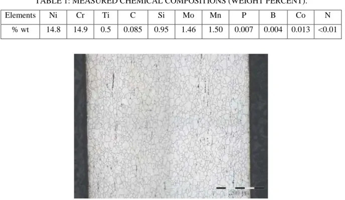
After the last solution-annealed treatment, the final geometry of the tube (outer diameter 6.55mm and thickness 0.45mm) was achieved by cold drawing (cold-working level of 23%). No thermal treatment was performed after the cold deformation step. The chemical composition directly measured in the tube is given in TABLE 1. The composition leads to a fully austenitic structure (grain size 20 m) without ferrite. Only primary TiMo(C,N) nitro-carbides are present in the microstructure. Alignment of primary precipitates in the drawing direction are visible in the metallography displayed in FIG. 1.
TABLE 1: MEASURED CHEMICAL COMPOSITIONS (WEIGHT PERCENT).
Elements Ni Cr Ti C Si Mo Mn P B Co N
% wt 14.8 14.9 0.5 0.085 0.95 1.46 1.50 0.007 0.004 0.013 <0.01
FIG. 1. Metallography of the cladding showing austenitic grains and primary carbide precipitates.
The fuel pin was irradiated in a standard Phénix assembly from 1982 to 1985 and re-irradiated from 1986 to 1987. A third irradiation of the same pin was performed in an experimental capsule from 1994 to 1998. The maximum dose of the cladding reached 130 dpa (NRT convention as computed by the Phénix neutronics code). A sample was taken from the higher part of the pin (gas plenum). This part of the tube is not in contact with fuel but is exposed to the highest temperature. From thermohydraulics computations, the irradiation temperature is between 600 and 625°C. From neutronics calculations, the final dose of the specimen is 40 dpa. 3 mm diameter disks were cut from the sample and thinned (thickness ~100 m) at the LECI hot laboratory at CEA Saclay. TEM discs were double-jet electropolished to perforation using 10% perchloric acid in ethanol at a temperature of -10°C. Due to the activity of the material, all the operations were performed in hot cell or in shielded glovebox. The thin foil dose measured at 10 cm is roughly 10 Sv/h.
Microstructural analyses were performed with a 300 kV FEI TECNAI 30 G2 TEM (LaB6
filament) equipped with an ORIUS 200D GATAN CCD Camera and an EDAX Energy Dispersive X-ray (EDX) system.
3. Unirradiated microstructure
TEM examination before irradiation shows a high dislocation density and mechanical twins due to the 20% cold working (See FIG. 2.). Induced by the cold deformation, local rearrangements of dislocations into cells are observed. Only primary TiMo(C,N) precipitates are present and no nanoprecipitates of rich-Cr carbides were detected.
FIG. 2. Bright-field TEM image showing the general microstructure before irradiation with high dislocation density, twins and few dislocation cells as well as primary Ti-Rich MC precipitates.
4. Microstructure after irradiation
Dislocation network A possible high-temperature issue of cold-worked Ti-stabilized steels is
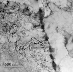
the risk of extensive recovery and possibly radiation-induced recrystallization during service life. Studies suggest that 15-15Ti alloys with high Si can recrystallize at a lower temperature than under thermal aging [1]. In the present examination, extensive primary recrystallization did not occur. However recovery mechanisms are clearly visible and caused a decrease of dislocation density. Rearrangement of dislocations and creation of free dislocation cells with a uniform TEM contrast is shown in FIG. 3. This dislocation-free zones are often formed at triple-junction points and could act as recrystallization nuclei.
FIG. 3. TEM bright field image of dislocations microstructure showing rearrangement due to recovery mechanisms.
Nanoprecipitation Ti-stabilized alloys were designed to create a fine dispersive precipitation
of Ti-rich MC precipitates when exposed to a high temperature thermal treatment. As shown in FIG. 4, MC were identified in bright field condition using the Moiré fringes (caused by the slight difference in the Fm3m lattice parameter between the precipitates and matrix) with a diffraction vector g=<002>. In this condition, the measured average spacing of the Moiré fringes gives a MC lattice parameter of a0 = 0.42 nm (assuming matrix lattice parameter a0 =
0.36 nm measured in the unirradiated sample). As in thermal treatments, the nucleation of MC is clearly enhanced in dislocations. The MC nanoprecipitation is homogeneously distributed in the sample.
FIG. 4. TEM image of nanoprecipitates MC (Moiré fringes) in bright field condition with diffracting vector g=<002>. Red arrow shows a small bubble nucleated at the TiC-matrix interface.
Frank loops Faulted Frank loops were identified in dark field images by the rel-rod technique
(see FIG. 5). The largest loops reach 60 nm in size. Larger faulted loops are not present because they are unstable and tend to unfault. Frank loops are homogeneously present in the sample, except inside free dislocation cells indicating that recovery process eliminates Frank loops.
FIG. 5. Dark field TEM image with the rel-rod technique of Frank loops (1-1 1) in two-beam condition B=[110] g=<-113> (left Figure) and the corresponding bright field image (right Figure) Bubbles and vacancy clusters: small bubbles are visible inside matrix grains and in grain
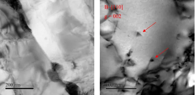
boundaries (see FIG. 6.). Some bubbles also nucleate heterogeneously at nanoprecipitate surfaces (FIG. 4) and at interfaces between matrix and larger precipitates (FIG. 7). The presence of large cavities (vacancy clusters) is not expected at 600°C because of the high probability of thermal dissociation. The stable bubbles observed in the present work are more likely helium bubbles. The helium generation rate in the upper part of the cladding is between 0.2 and 0.5 appm/dpa (due to n, reactions). In the literature [3], the formation of helium bubbles at grain boundaries is believed to contribute to the embrittlement of irradiated austenitic steels at high temperature (reduction of ductility in tensile test, reduction of rupture time in creep test). Note that very few studies with neutron-irradiated samples directly show the presence of helium bubbles. Most of the data come from helium-implanted samples or indirect correlations between creep properties and helium content.
Triangular-shaped defects with a rather low density are also observed with sample oriented in two beam condition B=[110] g=<002> as shown in FIG. 6. Triangular-shaped contrasts in TEM image can be the result of overlapping defects in the electron beam direction. Stacking Fault Tetrahedra (SFT) have also a similar contrast but were rarely observed in commercial steels irradiated at 600°C [2]. Further examinations are needed to determine the nature of these defects.
FIG. 6. TEM bright field image showing intergranular bubbles between precipitates (left figure) and triangular-shaped defects, (right figure) indicated by the red arrows.
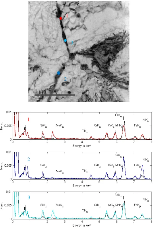
Intergranular precipitation: One of the striking feature of the irradiated microstructure is the
abundant presence of intergranular precipitates as displayed in FIG. 7. Coarse precipitates are also formed around primary MC, inside matrix grains. Several types of precipitates coexist as indicated by EDS (Energy Dispersive X-ray Spectroscopy) analysis in FIG. 8. Compared to the matrix, one type of precipitates is enriched in Ni, Ti and Si which is consistent with the G phase composition [4]. Another family of precipitates is enriched in Mo and Si (Si/Mo ~0.5). This type of precipitate contains a high density of stacking faults as observed on the bottom-right image of the FIG. 7. Above 600°C, the literature for Ti-stabilized austenitic steel reports the formation of laves phases (Hexagonal structure with space group P63/mmc) with high Mo
contents and appearing as faulted laths. M6C (space group Fd3̅m diamond cubic) and G phases (fcc structure with space group Fm3m) are also commonly observed. Selected Area Diffraction (SAD) studies are in progress to identify the crystallographic structure of the precipitates and to confirm their nature.
B~[110] g = 002
FIG. 7. Overview of coarse intra and intergranular precipitates. Note that precipitate surfaces promote bubble nucleation.
FIG. 8. EDS Spectrum of matrix (black curves) compared with several EDS spectra of precipitates (color curves). Spectra are not corrected for Mn radioactivity.
1 3 2 1 3 2
5. Conclusion
This first TEM examination reveals key points in the behavior of Si-enriched 15-15Ti irradiated at high temperature > 600°C up to 40 dpa. Significant structure recovery occurred but this alloy resists to irradiation-induced recrystallization. It is well known [5] that the microstructural evolution in irradiated austenitic steels can change fracture modes by promoting intergranular failures and reduce creep ductilities and rupture times. Different processes occured:
Matrix hardening: this work shows that a rather high density of defects still exists after irradiation around 600°C: Ti-rich MC nanoprecipitates and Frank loops.
Grain boundary embrittlement: many intergranular rupture creep models are based on the assumption that helium bubbles act as preferred sites for cavity nucleation [6]. This work confirms that small bubbles are present in grain boundaries, but at higher dose, coarse intergranular precipitation might have a more important role in grain boundaries embrittlement. Work is still on-going to identify the nature of precipitates.
6. Acknowledgements
V. Cloute-Cazalaa, C. Desserouer are deeply acknowledged for the preparation of irradiated thin foils. The authors thank B. Verhaeghe, B. Rouxel and M. Kountchou for fruitful discussions.
7. References
[1] VAIDYA, W.V., et al., “Radiation-Induced Recrystallization, its Cause and Consequences in Heavy-Ion Irradiated 20% Cold-Drawn Steels of Type 1.4970”, J. Nucl. Mat. 113 (1983) 149-162.
[2] SCHIBLI, R., et al., “On the formation of stacking fault tetrahedra in irradiated austenitic stainless steels – A literature review”, J. Nucl. Mat. 442 (2013) 761-767.
[3] DAI, Y, et al., “The Effects of Helium in Irradiated Structural Alloys”, Comprehensive Nuclear Materials, Cambridge University Press, 2012.
[4] MAZIASZ, P.J, “Overview of microstructural evolution in neutron-irradiated austenitic stainless steels” ”, J. Nucl. Mat. 205 (1993) 118-145.
[5] WARD, A.L. “Ductility Loss in Fast Reactor Irradiated Stainless Steel”, Nucl. Tech, 9, 771-772 (1970).
[6] VAGARALI, S.S “A Creep Fracture Model for Irradiated and Helium Injected Austenitic Stainless Steel”, J. Nucl. Mat., 103 & 104, 1239-1244, (1981).


![FIG. 5. Dark field TEM image with the rel-rod technique of Frank loops (1-1 1) in two-beam condition B=[110] g=<-113> (left Figure) and the corresponding bright field image (right Figure)](https://thumb-eu.123doks.com/thumbv2/123doknet/12678705.354248/6.892.133.746.258.554/dark-technique-frank-condition-figure-corresponding-bright-figure.webp)