HAL Id: in2p3-00666091
http://hal.in2p3.fr/in2p3-00666091
Submitted on 3 Feb 2012
HAL is a multi-disciplinary open access
archive for the deposit and dissemination of
sci-entific research documents, whether they are
pub-lished or not. The documents may come from
teaching and research institutions in France or
abroad, or from public or private research centers.
L’archive ouverte pluridisciplinaire HAL, est
destinée au dépôt et à la diffusion de documents
scientifiques de niveau recherche, publiés ou non,
émanant des établissements d’enseignement et de
recherche français ou étrangers, des laboratoires
publics ou privés.
What could be a radioactive ion beam facility at GANIL
A. Chabert
To cite this version:
A. Chabert. What could be a radioactive ion beam facility at GANIL. EPAC 92 - Third European
Particle Accelerator Conference, Mar 1992, Berlin, Germany. pp.412-414, 1992. �in2p3-00666091�
412
WHAT COULD BE A RADIOACTIVE
ION BEAM FACILITY
AT GANIL.
A. Chabert and the Development Group.
GANIL-BP 5027 - F14021 Caen Cedex.
Abstract 2. AN ECR RADIOACTIVE ION SOURCE GANIL provides high intensity ion beams from C
(100 MeV/u-2 1013pps) to U (25 MeV/u-2 lOlo pps) and secondary beams produced by fragmentation in the .50- 100 MeV/u ‘energy range are routinely used by the physicists in well equiped experimental areas . A further step in the direction of R.I.B. has been investigated : radioactive atoms produced through the interactions of the GANIL beams in thick targets will be ionized using a dedicated E.C.R. ion source, accelerated up to some tens of MeV/u in a post- accelerator and used in the existing experimental areas.
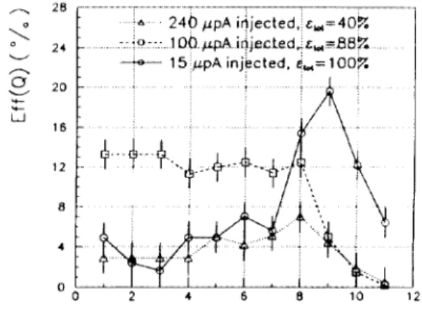
Preliminary studies using the GANIL ECR ion source CAPRICE indicate that it should be possible to ionize = 100% of an incoming low flux of atoms (< 10 ppA) and to obtain between 10 and 25% of the ions in their most probable charge state. Moreover, the usable charge over mass ratios obtained in CAPRICE are always 1 0.1 (U’24). Results for Ar are displayed on figure 2.
I. INTRODUCTION
4 240 ppA iijected. c,=40% .-.-io--:. loo.@ iejected,&,-Et3%
---te--- 15 ppA inj!cted. &= 100X ,
Our R.I.B. project is based upon the existing heavy ion accelerator associated with well equiped experimental areas in a facility widely opened to the international nuclear physic community.
The energetic light ions (5 100 MeV/u) can be compared with high energy protons (> 1 GeV) in producing radioactive atoms through their interactions in a thick target ; this is illustrated on figure 1 giving the cross sections for the production ‘of the Rb isotopes using either a 77 MeV/u C
beamorapbeaminanUtargetlll. OO 2 * 6 6 10 1 Moreover., using a primary ion beam, it will be possible to
optimize the choice “projectile - target” in order to enhance the production of a given isotope and, the target being thinner in the case of ions, extraction should be eased.
From these considerations it results that, for example, a 5.1013p.o.s., 95 MeV/u Ne beam as delivered bv GANIL
Q+Af Fig. 2 : Charge state distribution and ionization efficiency for Ar as measured in CAPRICE (10 Ghz).
The ECR ion source working in the highly radioactive environment of the target, it is more appropriate to built it using only permanent magnets ; such an ECR ion source, NANQGAN, has been developed at GANIL and a bench was built in order to test and to optimize the production of radioactive ions using the GANIL beams associated with a dedicated target-ECR ion source system : the very first results are more than encouraging 121.
10 - ;1 c 0 z :: I- 6 s Is’-
should compare with a 2 GeV- 10~ A p beam. . , , , , ( ,, , , 1,, ( 1 I ‘ , , .paGev “p 4aw *‘*v _ Rb l c77Mevhuckon a p 156 Hey - -.OP 1 Gh’
,u”~-o~o*
d
7”
a-* --;d.*&,\:,
i:
JOQo
d w
*‘,$’
F
2’
:
.I
a /
:
\
‘7
’ j
1.
, ,:’
a !
:i
f
L
‘/
a I
I
a
‘h
I,’
I
i
IbL I : I I 1 t I I 1 8 I 1 1 1 t 1 1 4 1 0 1 1 * I
76 78 60 62 84 66 66 90 92 94 96 98 AFig. 1 : Isotopic distributions of Rb in 12C + 238U and P + 238U systems ltl.
Therefore, GANIL provides a very competitive primary beam and due to the existing experimental areas we are only concerned with the post acceleration of these radioactive atoms and first to their ionization.
According to these considerations we base our project on such an ion source to be optimized for this particular application in order to obtain , as in CAPRICE, (Q/A)BcR > 0.1 with a high efficiency for all the ions.
3. THE POST-ACCELERATOR
We will choose a linear accelerator using superconducting independently phased cells grouped in a succession of cryostats. Such a well known solution seems to fulfil our main requirements : good transmission, easy tuning, fast energy variation, reliability. Moreover, due to the modularity of such an accelerator, it is possible to follow to a step by step construction, the beam being used at each step.
Our goal is to accelerate the whole range of masses above the coulomb barrier and we consider two steps :
- first step : U up to p 10 MeV/u (light ions up to m 20 MeV/u),
- second step : U up to p 20 MeV/u (light ions up to a 50 MeV/u).
413
3.1. 7he stripping energy
As we are looking for energies above 20 MeV/u the accelerator will be divided in a pre and a post-stripper. The stripping energy is determined by finding the minimum of the sum of the voltage gains of the pre and post-strippers, keeping into account the efficiency of the stripping process. It appears that the stripping energy has to be chosen around 3 MeV/u giving XV a 110 MV (full project) and a stripping efficiency going from p 100% for light ions down to m 15% for the heaviest ones.
3.2. T%e superconducting cells
A number of structures have been carefully studied and used for a long time. We will try, as much as possible, to use or to adapt existing ones.
- The very low energy part : the I.QWR (interdigital quarter wave resonator) of Argonne I31 will be used up to 0.9
* 1.2 MeV/u depending of the ion mass. The injection energy could be as low as 25 keV/u, so that, the ion source has to IX placed on a 250 kV platform (Q/A > 0.1).
The basic frequency will then be 24.25 or 12.125 MHz (buncher frequency) and this low energy part providing 8.75 MV will consist of 3 cryostats of the Argonne type housing 16 LQWR (of the 4 types used at Argonne) and the associated superconducting solenoids.
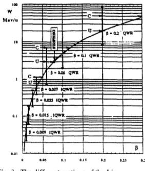
- The second part of the prestripper : in order to reach the stripping energy 3 -+ 7 MeV/u, we choose a 2 gap QWR like those developped at JAERI 141. We will adapt these resonators to fiopt = 0.06 and to a multiple of 24.25 MHz . Using a 72.75 MHz QWR and expecting 6 MV/m on a 16 cm active length, we need 2F1 cells in 7 cryostats (similar to the JAERJ ones) to obtain the required 21 MV. Transverse focusing is obtained by means of room temperature quadrupoles (Legnaro or JAERI scheme). too W Msvlu to 1 0.1 O.DI D 0.0s 0.1 cl.,3 01 0.23 P.3
Fig. 3 : The different sections of the Linac
- The post-stripper : it is divided into two parts (corresponding to the two steps of the project) with Popt respectively equal to 0.1 and 0.2. For the first step we will adapt a QWR at 121.25 MHz ; in this case, still for 6 MV/m on an active length of 16 cm, we will need 36 cells to get the 27.5 MV required to obtain 9 MeV/u for the heaviest ions. The remaining SO MV necessary to obtain 20 MeV/u for these same ions (step 2) will be given either by similar QWR (169.75 MHz, 23 cm, 6 MV/m for instance) or by more efficient resonators if any.
On figure 3 we give the different sections of the accelerator together with the energies obtained for light and heavy ions. A sketch of the layout of such a post-accelerator is shown on figure 4.
Test Fdily
414
4. THE BEAM ANALYSIS Such a solution should allow : The secondary beam intensities will be very low so that
we will have to optimize the beam transmission and to develop special beam diagnostics. The other main problem concerns the beam purification ; a given isotope among many other ions of similar Q/A having to be transfered to the experimental areas.
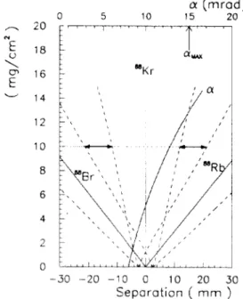
A first selection (Am/m a IO- 2, will be done just behind the ion source followed by a second one (Am/m a 10m3) after the HT platform. Then, as soon as the energy is high enough, i.e either after the stripper or at full energy, we intend to use the difference in the ion energy loss in a thin foil followed by a conventional spectrometer (dispersion 2 - S mm?% ; 0 a 15mrad, x a f O.Smm) in order to select the ions. 0 5 10 01 (mrad) 15 20 20 18 16 14 12 10 8 6 4 2 0
,““I(“’
‘I
’
auu:
mKr 6 -30 -20 -10 0 10 20 30 Separation ( mm )Fig. 5 : A =: 88 isobar separation at 15 MeV/u and beam divergence out of the target.
A 1 6 I '5 - 10 45
,,A,’
,’
I
i
,,’
1
0 ’ ,-_ ,_._, ..>- --L A I L-i----. 0 0 40 80 120 160 200 Mass ( uma ) Fig. 6 : Beam energy Ei allowing the separation of isobars and energy I!! out of the target.- to separate the ions having identical Q/A but different A : in this case very thin foils (Al or C) are quite efficient,
- to separate the isobars having the same Q/A : if we suppose a beam characterised by AW/W a f IOms and u m 471mm.mrad and taking into account the straggling in the foil (energy and angle) we obtain the results shown on figures S and 6 (the beam widths are taken as f 20).
5. CONCLUSION
A proposal for producing secondary radioactive ion beams up to the Fermi energy is outlined ; it is based upon :
- the GANIL heavy ion beams used as the primary beam, - a full permanent magnet ECR ion source providing Q/A 2 0.1 for all ions with a good efficiency,
- a superconducting linear accelerator directly derived from wellknown realizations or projects, in particular those of Argonne, Legnaro and JAERI,
- the existing experimental areas and data acquisition systems of GANJL to perform the experiments.
6. REFERENCES
[ 11 - De Saint Simon M. et al. - “Jndependant cross sections of Na, K, Rb, Cs and Fr isotopes produced in Ta and U targets bombarded by I2 C ions up to 77 MeV/nucleon” - Phys Rev. C-Vol. 26 - nb 6. p. 2447-2457 - 1982. [21 - P. Sortais et al. “Latest developemnts on multicharged
ECR ion sources” - These proceedings.
131 - Shepard K.W. “Status on RF superconductivity at Argonne” -Proc. 4th.workshop on RF superconductivity. Kek - Tsukuba. Japan - 1989. [4] - Takeuchi S. et al. “Progress in RF superconductivity for
heavy ion acceleration at JAERI”. Prcc. 4th.workshop on RF superconductivity. Kek. Tsukuba. Japan- 1989.