HAL Id: hal-00648507
https://hal.archives-ouvertes.fr/hal-00648507
Submitted on 5 Dec 2011
HAL is a multi-disciplinary open access
archive for the deposit and dissemination of
sci-entific research documents, whether they are
pub-lished or not. The documents may come from
teaching and research institutions in France or
abroad, or from public or private research centers.
L’archive ouverte pluridisciplinaire HAL, est
destinée au dépôt et à la diffusion de documents
scientifiques de niveau recherche, publiés ou non,
émanant des établissements d’enseignement et de
recherche français ou étrangers, des laboratoires
publics ou privés.
To cite this version:
Sylvie Treuillet, Eric Royer. Outdoor/Indoor Vision Based Localization for Blind Pedestrian
Navi-gation Assistance. International Journal of Image and Graphics, World Scientific Publishing, 2010,
pp.481-496. �hal-00648507�
OUTDOOR/INDOOR VISION-BASED LOCALIZATION FOR BLIND PEDESTRIAN NAVIGATION ASSISTANCE
SYLVIE TREUILLET Institut PRISME, Universit´e d’Orl´eans,
Ecole Polytechnique, 12 rue de Blois, 47067 Orl´eans, FRANCE [email protected]
ERIC ROYER
LASMEA, Universit´e Blaise Pascal, Campus des C´ezeaux, 63177 Aubi´ere, FRANCE
[email protected] Received (30 June 2008) Revised (21 September 2009)
Accepted (4 May 2010)
The most challenging issue facing the navigation assistive systems for the visually im-paired is the instantaneous and accurate spatial localization of the user. Most of the previously proposed systems are based on GPS sensors. However, the accuracy of low cost versions is insufficient for pedestrian use. Furthermore, GPS-based systems are con-fined to outdoor navigation and experience severe signal lost in urban areas. This paper presents a new approach for localizing a person by using a single body-mounted camera and computer vision techniques. Instantaneous accurate localization and heading esti-mates of the person are computed from images as the user progresses along a memorised path. A portable prototype has been tested for outdoor as well as indoor pedestrian use. Experimental results demonstrate the effectiveness of the vision based localization: the accuracy is sufficient for making it possible to guide and maintain the blind person within a navigation corridor less than one meter wide along the intended path. In com-bination with a suitable guiding interface, such a localization system will be convenient to assist the visually impaired in their everyday movements outdoors as well as indoors. Keywords: computer vision; indoor/outdoor localization; navigation assistance; visually impaired.
1. Introduction
A major political and technical challenge for a modern society is to find innovative solutions for effective assistance to increase the security and mobility of visually impaired persons travelling through city streets and buildings. For people who are blind, way-finding is dependent on the ability to remain localized and oriented. Recent work on assistive technologies for human localization has mainly focused on GPS (Global Positioning System).1,2,3,4,5 The shortcomings of GPS, however,
are well-known. A GPS sensor is ineffective indoors and in low cost versions it fails
to provide accurate spatial position (ten meters - for the best versions - is clearly inadequate to keep a walker along the intended path). Furthermore, the signal cannot be tracked when the blind person moves into masking areas such as along high walls or tall buildings. While some studies have tested differential GPS which provides an accuracy of around one meter, it is costly and cumbersome equipment which needs fixed ground stations and is only efficient outdoors.6,7
Alternative devices have been designed to assist blind people in their mobility and orientation tasks indoors, such as ultrasound, 8 or radio frequency
identifi-cation transponders, 9 using a robotic ”dog-guide”, 10 or an instrumented white
cane. 11 Several real-time location systems (RLTS) based on distributed wireless
sensor networks have also been tested for indoor human position sensing. Wireless LAN (WLAN), ultra-wide-band (UWB), and radio frequency identification (RFID) have been combined with building information model (BIM) to propose an emer-gency navigation system in complex buildings. 12 The proposed system enables the positions of rescuers to be determined to within a few meters once a minute. However, guiding blind people along their route requires higher accuracy and speed rate. A recent study conducted at Brunel University campus in Uxbridge points up considerable difficulties in establishing a navigation system for visually impaired people with WiFi.13. A navigation aid based on a commercial UWB asset tracking system has been evaluated with blindfolded subjects. 14 Results show that
navi-gation system dramatically outperforms the non-guided condition without to equal a normal vision control condition. Promising results have also been obtained in a restricted area with a grid of passive RFID tags integrated in the floor. 15 The
RFID reader may be attached to a cane, a shoe or a handheld device such as a smart phone. To obtain a suitable positioning accuracy, however, it is necessary to install enough RFID tags, with an ideal density of about half a meter spacing, and the walking speed of sighted people is generally too high for reading the tags. To make them suitable for indoor navigational aid, the detection range of commercially available RFID tags must be extended. 16
Although they are low cost technologies, installing dedicated WLAN transmit-ters or radio frequency tags in large building complexes or a whole city would be expensive, inflexible and inconvenient. To sum up, localization systems with suf-ficient accuracy for blind pedestrian applications are currently based on ground installations (DGPS, RLTS), and Drishti 8 is the only system which proposes a
combined outdoor/indoor system.
In order to be widely applicable, the design of an individual localization system needs to be based on wearable, low cost and mobile technologies, free from collective equipment. To achieve this aim, we propose a new vision based solution derived from the autonomous navigation of wheeled robots to assist the visually impaired in their everyday movements outdoors as well as indoors. This computer vision based system requires no environment instrumentation: instantaneous accurate localization and heading estimates of the user are computed only from images provided by a
body-mounted camera as the user progresses along a memorized path.17 This real time
localization is available provided that a video sequence has been previously recorded during a learning trip. For the time being, the vision system is used only to localize and guide the walker along the intended path, it does not substitute for the long white cane in obstacle avoidance. The following section describes our vision based positioning system. Some experimental results with a first wearable prototype are given in section 3. The conclusion and future works are discussed in the last section.
2. Vision-based positioning 2.1. Related work
Vision based localization has become an active research area in the last few years. Usually, the camera pose is computed with reference to the environment, and the system needs to build a map from features detected in the images. The system then matches features between the current frame and the memorized ones in the map to compute the pose of the camera. The mapping step can either be done at the same time as the camera localization or beforehand in an offline learning step. The first approach is called visual SLAM (Simultaneous Localization And Mapping). Most of the developments done in the robotics community rely on odometry as well as vision, 18 but these techniques cannot be adapted to wearable cameras.
Visual SLAM with a single hand held camera was recently achieved by Davison.19 However, accurate mapping requires considerable computing power with closed loop paths to refine the map of the robot environment, meaning that this approach can only deal with a small number of features and a moderately sized environment. We have therefore preferred to adopt a structure from motion approach to first build the route mapping. Several researchers have developed structure from motion algorithms based on monocular vision.20,21,22These algorithms use an initialization
step followed by bundle adjustment to build a map from an image sequence without the need for other sensors.23
2.2. Approach overview
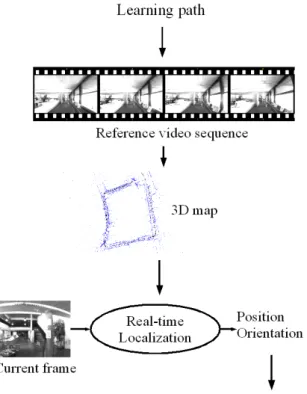
The localization system relies on two steps (Figure 1): a preliminary learning path and a real time localization for navigation assistance. During a learning trip, a video sequence is recorded by the on-board vision system and processed off-line to automatically build a large set of natural landmarks by applying a structure from motion algorithm. This algorithm recovers both the motion of the camera and the geometry of a rigid surrounding scene by automatically recognizing some land-marks through the image sequence (angular points on buildings, windows, doors, billboards, trees,. . . ). The memorized information consists in a set of selected key frames corresponding to different camera positions along the learning path and a 3D map of the environment. During navigation assistance, ego motion of the cam-era is computed as the trip progresses by matching the stored 3D visual landmarks
Fig. 1. Overview of the vision based localization system.
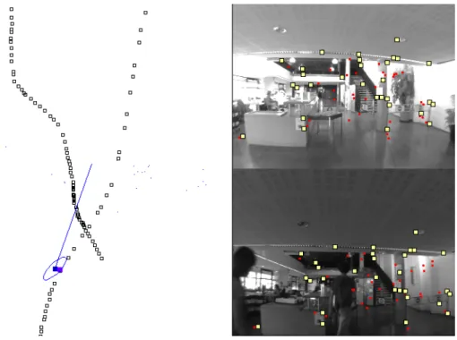
with their projections observed in the current frame. Figure 2 shows a result of localization during a walk through the university library. As the camera is rigidly attached to the carrier, it provides its instantaneous localization and orientation (6 DoF) along the route. Even if transient obstacles (pedestrian, car, advertising hoarding), that were not in the path of the memorized route, mask some part of the 3D environment, the camera localization can still be effective while there are at least a few tens of well recognized landmarks.
2.3. Map building from learning path
Every step in the structure from motion as well as the real-time localization relies on image matching. Points of interest are detected in each frame with a Harris24
Fig. 2. Left: Top view of a walk inside the university library. Empty squares represent all the camera positions selected during the learning path. The current position and heading estimates of the person over the intended path (colored square and vector), bounded with uncertainty ellipsoid on camera position estimates (extended 100 times). Right: Current frame captured by the camera (bottom) and the corresponding key frame memorized during the learning trip several days before (top). Large colored squares are the well matched points, small ones the unmatched.
for each interest point in the first frame, we select some corresponding candidate points in a rectangular search region in the second one. Then, a Zero Normalized Cross Correlation score is computed between their neighborhoods, and the pairs with the best scores are kept to provide a list of corresponding point pairs between the two frames. Matching methods with rotational invariance could also be used but they would require more computing power.
The goal of the reconstruction is to obtain the position of a subset of the cameras in the reference sequence as well as a set of landmarks and their 3D location in a global coordinate system. The structure from motion problem has been studied for several years and many different algorithms have been proposed depending on the assumptions made.25For our experiments, the camera was calibrated using a planar
calibration pattern. 26 Camera calibration is important because the wide angle lens used has a strong radial distortion. With a calibrated camera, the structure from motion algorithm is more robust and the accuracy of the reconstruction is
increased. In our application, the motion is mostly along the optical axis of the camera. Point triangulation must be done with small angles, which increases the difficulty of obtaining an accurate 3D reconstruction.
In the first step of the reconstruction, we extract a set of key frames from the reference sequence. Then we compute camera motion between key frames. Addi-tionally, the interest points are reconstructed in 3D and a small surrounding texture patch is memorized. These features will be the landmarks used for the localization process.
2.3.1. Key frame selection
Computation of the epipolar geometry is an ill conditioned problem if the camera motion is too small between two successive frames. The key frames are therefore selected to be as widely time-spaced as possible so long as the matching process is preserved in the images. The first frame of the sequence is always selected as the first key frame I1. The second key frame I2 is chosen as far as possible from I1
but with at least M common interest points between I1 and I2. When key frames
I1. . . In are chosen, we select In+1(as far as possible from In) so that there are at
least M interest points in common between In+1 and In and at least N common
points between In+1and In−1. In our experiments we detected 1500 interest points
per frame and we chose M = 400 and N = 300.
2.3.2. Camera motion computation
For the first three key frames, the camera motion is recovered by computing the essential matrix between the first and last frames of the triplet using a sample of 5 point correspondences.27 There are at most 10 solutions for E. Each matrix E
gives 4 solutions for camera motion. The solutions for which at least one of the 5 points is not reconstructed in front of both cameras are discarded. Then the pose of the remaining camera is computed with 3 out of the 5 points in the sample. This process is carried out with a RANSAC approach : each 5 point sample produces a number of hypotheses for the 3 cameras.28The best one is chosen by computing the
reprojection error over the 3 views for all the matched interest points and keeping the one with the highest number of inlier matches. An algorithm is also required to compute the pose of the second camera. With a calibrated camera, three 3D points whose projections in the image are known suffice to compute the pose of the camera. Among the various methods compared by Haralick,29 we chose Grunert’s
method with a RANSAC approach.
For the following image triplets, a different method is used for computing camera motion. Assuming the locations of cameras C1 to CN are known, we can compute
camera CN +1by using the location of cameras CN −1and CN and point
projections are known in each image of the triplet. From the projections in images N − 1 and N , we can compute the 3D coordinates of point Xi. Then from the set of Xi and their projections in image N + 1, Grunert’s calibrated pose estimation
algorithm is used to compute the location of camera CN +1. In addition the 3D
locations of the reconstructed interest points are stored because they will be the landmarks used for the localization process. The advantage of this iterative pose estimation process is that it can deal with virtually planar scenes. After the pose computation, a second matching step is carried out with the epipolar constraint based on the pose that was just computed. This second matching step increases the number of correctly reconstructed 3D points by about 20 %.
2.3.3. Hierarchical bundle adjustment
The computation of camera CN depends on the results of the previous cameras, and
errors can build up over the sequence. In order to correct this problem, we use a bun-dle adjustment which provides a better solution. Bunbun-dle adjustment is a Levenberg-Marquardt minimization of the cost function f (C1
E, · · · , C N E, X
1, · · · , XM) where
CEi are the external parameters of camera i, and Xj are the world coordinates of point j. For this minimization, the radial distorsion of the 2D point coordinates is corrected beforehand. The cost function is the sum of the reprojection errors of all the inlier reprojections in all the images :
f (CE1, · · · , CEN, X1, · · · , XM) = N X i=1 M X j=1,j∈Ji d2(xji, PiXj) where d2(xj
i, Pixj) is the squared euclidian distance between PiXj the projection
of point Xjby camera i, and xj
i is the corresponding detected point. Pi is the 3 × 4
projection matrix built from the parameter values in CEi and the known internal parameters of the camera. Ji is the set of points whose reprojection error in image
i is less than 2 pixels at the beginning of the minimization. After a few iteration steps, Ji is computed again and more minimization iterations are performed. This
inlier selection process is repeated as long as the number of inliers increases. Computing all the camera locations and using bundle adjustment only once on the whole sequence could cause problems because increasing errors could produce an initial solution that is too far from the optimal one for the bundle adjustment to converge. It is therefore necessary to use the bundle adjustment throughout the reconstruction of the sequence, in a hierarchical fashion.25A large sequence is divided into two parts with an overlap of two frames in order to be able to merge the sequence. Each subsequence is recursively divided in the same way until each final subsequence contains only three frames. Each image triplet is processed as described in section 2.3.2. After each triplet has been computed a bundle adjustment is run over its three frames. Small subsequences are the merged into larger subsequences and a bundle adjustment is appleid after each merging operation. In order to merge two subsequences, we compute a best-fit rigid transformation so that the first two
cameras of the second subsequence are transformed into the last two cameras of the first subsequence. Merging is done until the whole sequence has been reconstructed. The reconstruction ends with a global bundle adjustment. The number of points used in the bundle adjustment is on the order of several thousands.
2.4. Real-time localization
The output of the learning process is a 3D reconstruction of the scene: we have the pose of the camera for each key frame and a set of 3D points associated with their 2D positions in the key frames. At the start of the localization process, no assumption is made about the camera localization. It is therefore necessary to compare the current frame to every key frame in order to find the best match. This is done by matching interest points between the two frames and computing a camera pose with RANSAC. The pose obtained with the highest number of inliers is a good estimation of the camera pose for the first frame. This step requires a few seconds but is needed only at the start. After this step, since we always have an approximate pose for the camera, we only need to update the pose, which can be done much faster.
The current frame is noted I. First we assume that the camera movement be-tween two successive frames is small. So an approximate camera pose (we note the associated camera matrix P0) for frame I is the same as the pose computed for the
preceding frame. Based on P0 we select the closest key frame Ik i.e. the shortest
euclidian distance between the camera centers. Ik gives us a set of interest points
Akreconstructed in 3D. We detect interest points in I and match them with Ak. To
do that, for each point in Ak, a correlation score is computed with all the interest
points detected in I which are in the search region. With P0, we can compute an
expected projection in I for each 3D visible landmark stored in Ak. The search
re-gion for the matching process is centered around the expected position and its size is small enough to enable real-time computing. The size of the search region may be adjusted based on the covariance matrix computed for the pose P0. This choice
is well adapted to a robot because its motion model is smooth and well known. We found however that a fixed sized region (20 × 12 pixels) works better for a wearable camera because the user can abruptly change direction at any time. It is important to have a very fast implementation of the pose computation so that the frame rate can be kept high and thus reduce camera movement between frames. After this matching is done, we have a set of 2D points in image I matched with 2D points in image Ik which are themselves linked to a 3D point obtained during the
reconstruc-tion process. With these 3D/2D matches a better pose is computed using Grunert’s method through RANSAC to reject outliers. This gives us the camera matrix P1
for I. The pose is then refined using an iterative method with some modifications in order to deal with outliers.30This is a minimization of the reprojection error for all the points using Newton’s method. At each iteration we solve the linear system J δ = e in order to compute a vector of corrections δ to be subtracted from the pose
parameters. e is the error vector formed with the reprojection error of each point in x and y. J is the Jacobian matrix of the error. In our implementation, the points used in the minimization process are computed at each iteration. We keep only the points whose reprojection error is less than two pixels. This threshold is relative to the accuracy of the Harris detector (about one pixel) with an additional margin of one pixel to select a sufficient number of inliers. We prefer to completely reject outliers instead of using an M-estimator mainly to reduce the computation time. As the pose converges towards the optimal pose, some inliers can become outliers and conversely. Usually, less than five iterations are enough to provide the localization and orientation of the camera (see Figure 2).
3. Pedestrian navigation assistance
The vision-based localization method described above has been extensively tested with wheeled robots and evaluated by comparison with the ground truth given by a differential GPS sensor. A localization accuracy of around 0.05m was achieved in experiences with wheeled robots.31We propose to adapt this system to pedestrian navigation by using a body-mounted camera and a wearable computer.
An initial prototype was developed to test the robustness of the vision based localization algorithm on bumpy walking routes (unlike the wheeled robots which move smoothly). Several video sequences were acquired along routes more than 100m long in various situations (indoor/outdoor, open/cluttered space, flat floor/stairs,. . . ). Different inexperienced visually impaired subjects tested the lo-calization system for several days or weeks after the video sequence acquisition of the learning path. The navigation performance can be analyzed by observing on the fly the path followed by the walker in comparison with the intended one (i.e. the reference path followed by the camera during the learning trip).
3.1. Experimental device
A photo of the experimental device is given in Figure 3. The pedestrian prototype is composed of a 2,8mm lens equipped with an AVT Guppy 044B camera (320x240 pixels resolution, diagonal field of view of 120 degrees) fixed on a body harness and connected to a wearable computer (Pentium M 1.86GHz 1 GB RAM). The intrinsic parameters of the camera including radial distortions are estimated by prior calibration.
After the initialization step, the vision system provides the current localization and also heading of the walker relative to the local segment of the reference path at a rate of 30 frames per second. Considering this current position, the walker may be continuously reoriented by suitable interface modalities so that to be kept in a navigation corridor along the intended path. To keep the walker as close as possible to the memorized path, directional prompts are given according to his adherence to the path (see Figure 3). The walker’s adherence is evaluated by the lateral space e between the camera position and the nearest point of the path. Then, for guiding
Fig. 3. Left: The pedestrian prototype with a chest mounted camera and a wearable computer in a back pack.Right: The walker is kept in a corridor along the intended path by directional prompts. His adherence to the path is defined by the angular deviation θ for joining the route 3 meters farther from the lateral space e between current position and the nearest point of the reference path.
facilities, the lateral space e is converted to an angular value for joining the route 3 meters farther on by θ = arctan[e/3]. If the absolute value of the angular deviation θ is higher than ten degrees, directional instructions are given to the walker. If not, the system confirms the walker in his path every second. We find that ten degrees is a reasonable value for quickly detecting a lateral deviation of about half a meter and proposing smooth reorienteering to join the intended route with an average walking speed of 1.5 meter par second. The walker is also informed of the system initialization or of any breaks in localization, and as soon as he has arrived at his destination.
In the initial version, two different guiding modalities were tested with head-phones: a speech-based interface or a regularly time spaced sonar sound effect. The verbal navigational prompts are of three types: ”turn left”, ”turn right” or ”straight ahead” depending on the walker’s angular deviation. Similarly, the sonar pings are respectively applied only in the left ear, only in the right ear or in both, with varying frequency depending on the pedestrian’s adherence to the path.
3.2. Results
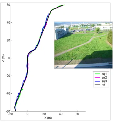
In order to illustrate the efficiency of the proposed vision system, Figure 4 shows the tracks of three blindfolded subjects navigating outdoors. Equipped with our vision based localization system, they were able to follow the reference path closely in unfamiliar open space without any reference points. Tables 1 and 2 give some
statistics on the navigation performance during this outdoor route and the indoor walk inside the library shown in the snapshot in Figure 2. Each subject walked each path only once after a short training phase with the system during a few minutes. The efficiency of the vision system is evaluated in terms of adherence of the walker to the memorized path in real-world conditions. This adherence is measured by the lateral space e between the camera position and the nearest point of the path 3. This metric includes the vision-based localization accuracy and the efficiency of the guiding prompt. We choose unfamiliar open spaces in order to test the localization and guiding efficiency without the possibility for the blind walker to use walls or other external structures as navigation aids.
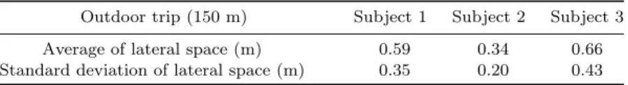
The observed average and standard deviation of the lateral space indicate that 95% of instantaneous lateral spaces are less than 1.2 meter, with an average of about half a meter, which is a good result since no optimization was carried out. Note that the guidance system includes no motion model and that except for the prior camera calibration, no harness calibration was made when changing participants. This demonstrates the relative robustness of the system to variations in acquisition conditions.
Table 1. Outdoor localization and navigation performance.
Outdoor trip (150 m) Subject 1 Subject 2 Subject 3 Average of lateral space (m) 0.59 0.34 0.66 Standard deviation of lateral space (m) 0.35 0.20 0.43
Table 2. Indoor localization and navigation performance.
Indoor trip (70 m) Subject 1 Subject 2 Subject 3 Average of lateral space (m) 0.36 0.40 0.47 Standard deviation of lateral space (m) 0.25 0.22 0.27
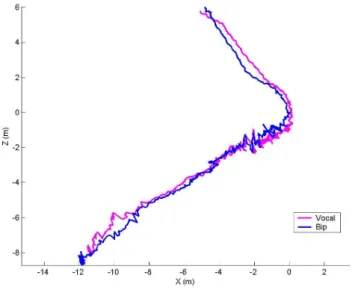
A comparison of the tracks obtained with different guiding modalities is illus-trated in Figure 5 along a totally open space indoor route with no guiding walls. Auditive feedbacks were the easiest to implement for a preliminary evaluation of guiding assistance from our vision-based localization system. No significant dif-ference was observed between voice versus beeping feedbacks. Nevertheless, it is necessary to compare the guiding modalities in greater depth with a larger number of subjects and scenarii. These experimental results demonstrate the effectiveness of the vision based localization system to keep the walker in a navigation corridor less than one meter wide along the intended path.
The start step of the localization process requires only a few seconds (for a global search without approximate pose of the camera), i.e. much faster than present GPS
Fig. 4. Outdoors tracks of three visually impaired subjects equipped with our vision based local-ization system in unfamiliar open space environment, and a surrounding view of the scene.
receivers. This start process is done every time the tracking is lost, and if the relocalization from key frames connected to the last memorized position fails. The only condition required for positioning to succeed is to compute more or less forty good matches in the current frame. This is generally possible even if some transient obstacles (not in the path of the memorized route) mask some part of the 3D environment. As can be seen on Fig. 2, our approach can also handle cases of loop path, since the observing direction of the camera is different. At present, the main limitation of this technique is the robustness of the matching process in the event of large changes in viewpoint. Rapid and unpredictable camera motion may cause loss of tracking. In particular, if the walker rapidly swivels the upper part of his body, the camera viewpoint may be too different for a sufficient number of memorized visual landmarks to be recognized. Such a failure case is illustrated in Figure 4 (stop before the end for one of the subjects). In the future, we will prevent this problem by employing more robust descriptors of texture templates for landmarks or an inter frame motion estimator to aid tracking. One solution would be to exploit the extra capabilities of smartphones (accelerometer and GPS) and future devices
(magnetic compass, gyroscopes) which could surely benefit visual tracking.
Fig. 5. Two successive tracks of the same blind subject guided by the verbal navigational prompts (vocal), respectively by the sonar interface (bip) with frequency according to the angular deviation.
4. Conclusions and Future Work
The guidance provided by a GPS sensor is insufficiently precise for pedestrian nav-igation and cannot be relied on indoors, underground or even when travelling near walls and buildings in an urban environment. This paper proposes a localization system based on an embedded camera which is an interesting alternative for guid-ing visually impaired people in their indoor/oudoor daily walks, supplementary to obstacle avoidance they can discern on their own using a long cane.
A wearable vision system has been presented for localizing a person on a memo-rized path. Vision based localization provides sufficient accuracy to keep the walker in a navigation corridor one meter wide, without the drawbacks of cumbersome and costly systems based on DGPS receivers. Our real-time localization system may be used for pedestrian navigation both outdoors and indoors without any dependen-cies to external instrumentation of infrastucture. This is clearly an advantage for the design a widely used autonomous system to assist visually impaired people.
Future work will focus on increasing the ergonomics and robustness of the system by working in collaboration with end-users. The key issue to improve guidance efficiency is to find the best communication modalities, taking into account the
psychological and ergonomic factors with a large panel of users with severe visual impairment in various situations. In particular, it will be interesting to investigate tactile feedback to prevent possible disorientation of blind individuals caused by overuse of the sound space.
Navigation control may be analysed on the fly by the quantitative measurements of path efficiency which will be a very useful tool to investigate different multimodal adaptive interfaces. We have observed that performance improves with practice. The machine needs to learn to work with the user and to adapt some walk models to each user. We also plan to investigate a second prototype comprising a eye-glasses on whitch a tiny camera and 3-axis gyroscopes are mounted to estimate head movements, and to develop applications on PDAs or smart phones. This system may also be combined with RFID tags judiciously placed in buildings to warn of obstacles (doors, stairs, etc).
The ultimate aim of the project is to develop a low cost and convenient embed-ded personal guidance system embed-dedicated to visually impaired users. Such a system may also be useful for locomotion learning of blind people or for elderly people with memory loss to improve their mobility and social integration.
Acknowledgements
The authors gratefully acknowledge the contribution of Gregory Gerenton and Niele Pouzet.
References
1. D. Brusnighan, M. Strauss, J. Floyd and B. Wheeler, ”Orientation aid implement-ing the Global Positionimplement-ing System” in Proc. of the Fifteenth IEEE Annual Northeast Bioengineering Conference p. 33-34 (1989).
2. J.Fruchterman, ”Talking maps and GPS systems” in Symposium on Technology to Assist the Blind and Visually Impaired (1996).
3. H. Makino, I. Ishii and M. Nakashizuka, ”Development of navigation system for the blind using GPS and mobile phone combination”, in Proc. of the IEEE Engineering in Medecine and Biology Society Vol. 2, p. 506-507 (1996).
4. J. Loomis, R. Golledge and R. Klatzky, ”GPS-based navigation systems for the visu-ally impaired”, in Fundamentals of Wearable Computers and Augmented Reality, W. Barfield and T. Caudell Eds., p. 429-446 (2001).
5. R. Kowalik, and S. Kwasniewski, ”Navigator: A Talking GPS Receiver for the Blind”, in Lecture Notes in Computer Science, Vol.3118, Computers Helping People with Special Needs, p. 446-449 (2004).
6. A.Helal, S. Moore, and B. Ramachandran, ”Drishti: An integrated navigation system for visually impaired and disabled”, in Proc. of the Fifth Int. Symposium on Wearable Computers, p. 149-156 (2001).
7. W. Balachandran, F. Cecelja, and B. Ptasinski, ”A GPS-based navigation aid for the blind” in Proc. of the Int. Symposium on Wearable Computers, p. 134-36 (2003). 8. L. Ran, S. Helal, and S. Moore S., ”Drishti: an integrated indoor/outdoor blind
nav-igation system and service”, in Proc. of the 2nd Conf. on Pervasive Computing and Communications, p. 23-32 (2004).
9. J. Na, ”The blind interactive guide system using RFID-based indoor positioning sys-tem”, in Lecture Notes in Computer Science, Vol. 4061, Computers Helping People with Special Needs, p. 1298-1305 (2006).
10. V. Kulyukin, C. Gharpure, J. Nicholson, and S. Pavithran, ”RFID in robot assisted indoor navigation for the visually impaired”, in Proc. of the IEEE Int. Conf. on Intel-ligent Robots and Systems, Vol. 2, p. 1979-1984 (2004).
11. J. Hesch, and S. Roumeliotis, ”An Indoor localization aid for the visually impaired”, in Proc. of IEEE Int. Conf. on Robotics and Automation, p. 3545-3551 (2007). 12. U. Ruepple and K.M. Stuebbe, ”BIM-Based Indoor Emergency Navigation System
for Complex Buildings” in TSINGHUA SCIENCE AND TECHNOLOGY, Vol.13-S1, p. 362-367 (2008).
13. K. Alhajri, N. Al-Salihi, V. Garaj and W. Balachandran, ”The performance of WiFi network for application in a navigation system for visually impaired people”, in Wire-less Telecommunications Symposium, p. 243-249 (2008).
14. T.H. Riehle, P. Lichter and N. Giudice, ”An indoor navigation system to support the visually impaired” in Proc. of the IEEE 30th Annual International Conference of the EMBS, p. 4435-4438 (2008).
15. S. Willis and S. Helal, ”RFID information grid for blind navigation and wayfinding”, in Proc. of the Ninth IEEE International Symposium on Wearable Computers, p. 34-37 (2005).
16. A.Y.J. Szeto and S.K. Sharma, ”RFID Based Indoor Navigational Aid for Persons with Severe Visual Impairments”, in Proc. of the 29th Annual International Conference of the IEEE Engineering in Medicine and Biology Society, p. 6360-6363 (2007). 17. S. Treuillet, E. Royer, T. Chteau, M. Dhome, J.M. Lavest,”Body mounted vision
sys-tem for assisting visually impaired to outdoor and indoor way finding”, in Proc. of the Conference on Assistive Technology for People with Vision and Hearing Impairments, Granada, Spain (2007).
18. S. Se, D. Lowe and J. Little,”Mobile Robot Localization and Mapping with Uncer-tainty using Scale-Invariant Visual Landmarks”,in International Journal of Robotic Research, Vol.21(8), p. 735-760 (2002).
19. A. J. Davison, I. Reid, N. Molton and O. Stasse,”MonoSLAM: Real-time single camera SLAM”, in Transactions on Pattern Analysis and Machine Intelligence, Vol. 29(6), p. 10521067 (2007).
20. P. Beardsley, P. Torr and A. Zisserman,”3D Model acquisition from extended image sequences”, in Proc. of the European Conference on Computer Vision,p. 683-695 (1996). 21. M. Pollefeys, R. Koch, M. Vergauwen and L. Van Gool, ”Automated reconstruction of 3D scenes from sequences of images”, in ISPRS Journal Of Photogrammetry And Remote Sensing, Vol. 55(4),p. 251-267 (2000).
22. A.W. Fitzgibbon and A. Zisserman, ”automatic camera recovery for closed or open image sequences, in Proc. of European Conference on Computer Vision, p. 311-326 (1998).
23. B. Triggs, P. McLauchlan, R. Hartley and A. Fitzgibbon, ”Bundle Adjustment - A Modern Synthesis”, in Vision Algorithms: Theory and Practice, Ed. Triggs W., Zisser-man, A. and Szeliski, R., Springer Verlag Series, Lecture Notes in Computer Science, p. 153-177 (2000).
24. C. Harris, and M. Stephens, ”A combined corner and edge detector”, in Proc. of the Alvey Vision Conference, p. 147-151 (1988).
25. R. Hartley and A. Zisserman, Multiple view geometry in computer vision, Cambridge University Press (2000).
pattern to achieve a reliable camera calibration ?”, in Proc. of the European Conference on Computer Vision, p. 158-174 (1998).
27. D. Nist´er, ”An efficient solution to the five-point relative pose problem”, in Proc. of the Conference on Computer Vision and Pattern Recognition, p. 147-151 (2003). 28. O. Fischler, and R. Bolles, ”Random Sample Consensus: a paradigm for model fitting
with application to image analysis and automated cartography”, in Communications of the Association for Computing Machinery, Vol.24, p. 381-395 (1981).
29. R. Haralick, C. Lee, K. Ottenberg, and M. Nolle, ”Review and analysis of solutions of the three point perspective pose estimation problem”, in International Journal of Computer Vision, Vol.13, p. 331-356 (1994).
30. H. Arajo, R. Carceroni, and C. Brown, ”A fully projective formulation to improve the accuracy of Lowe’s pose estimation algorithm”, in Computer Vision and Image Understanding, Vol.70, p. 227-238 (1998).
31. E. Royer, M. Lhuillier, M. Dhome, and T. Chateau, ”Localization in urban envi-ronments : monocular vision compared to a differential GPS sensor”, in Proc. of the Conference on Computer Vision and Pattern Recognition, Vol. 2, p. 114-121 (2005).
Photo and Bibliography
Sylvie Treuillet received the Master degree in electrical en-gineering from the University of Clermont-Ferrand, France in 1988. From 1988 to 1990, she worked in a private com-pany in Montpellier developing image processing and pat-tern recognition methods in automatics cytogenetics. She then joined the academic research laboratory LASMEA and was awarded her PhD degree in computer vision in 1993 at the University of Clermont-Ferrand, France.
Since 1994, she has been assistant professor in computer sciences and electronic engineering at the Ecole Polytechnique of the University of Orleans, France. Her research interests include computer vision for 3D object modeling, pattern recog-nition, and color image analysis for biomedical or industrial applications.
Eric Royer received his Ph.D. in computer vision from Universit´e Blaise Pascal, Clermont-Ferrand, France in 2006. He is currently assistant professor at Universit´e d’Auvergne, Clermont-Ferrand, France. His research interests include ge-ometric vision, image matching, SLAM and their applica-tions to mobile robotics and assistive systems.