Publisher’s version / Version de l'éditeur:
Vous avez des questions? Nous pouvons vous aider. Pour communiquer directement avec un auteur, consultez la
première page de la revue dans laquelle son article a été publié afin de trouver ses coordonnées. Si vous n’arrivez
pas à les repérer, communiquez avec nous à PublicationsArchive-ArchivesPublications@nrc-cnrc.gc.ca.
Questions? Contact the NRC Publications Archive team at
PublicationsArchive-ArchivesPublications@nrc-cnrc.gc.ca. If you wish to email the authors directly, please see the
first page of the publication for their contact information.
https://publications-cnrc.canada.ca/fra/droits
L’accès à ce site Web et l’utilisation de son contenu sont assujettis aux conditions présentées dans le site
LISEZ CES CONDITIONS ATTENTIVEMENT AVANT D’UTILISER CE SITE WEB.
Electrochemistry Communications, 119, 2020-08-26
READ THESE TERMS AND CONDITIONS CAREFULLY BEFORE USING THIS WEBSITE.
https://nrc-publications.canada.ca/eng/copyright
NRC Publications Archive Record / Notice des Archives des publications du CNRC :
https://nrc-publications.canada.ca/eng/view/object/?id=0c3cb5ac-7a2d-4290-b9e5-7db684c32ac2
https://publications-cnrc.canada.ca/fra/voir/objet/?id=0c3cb5ac-7a2d-4290-b9e5-7db684c32ac2
NRC Publications Archive
Archives des publications du CNRC
This publication could be one of several versions: author’s original, accepted manuscript or the publisher’s version. /
La version de cette publication peut être l’une des suivantes : la version prépublication de l’auteur, la version
acceptée du manuscrit ou la version de l’éditeur.
For the publisher’s version, please access the DOI link below./ Pour consulter la version de l’éditeur, utilisez le lien
DOI ci-dessous.
https://doi.org/10.1016/j.elecom.2020.106824
Access and use of this website and the material on it are subject to the Terms and Conditions set forth at
The role of Ru clusters in Fe carbide suppression for the reverse water
gas shift reaction over electropromoted Ru/FeOₓ catalysts
Contents lists available at ScienceDirect
Electrochemistry Communications
journal homepage: www.elsevier.com/locate/elecom
The role of Ru clusters in Fe carbide suppression for the reverse water gas
shift reaction over electropromoted Ru/FeO
x
catalysts
Christopher Panaritis
a, Johnny Zgheib
a, Martin Couillard
b, Elena A. Baranova
a,⁎a Department of Chemical and Biological Engineering, Centre for Catalysis Research and Innovation (CCRI), University of Ottawa, 161 Louis-Pasteur, Ottawa, ON K1N
6N5, Canada
b National Research Council of Canada, 1200 Montreal Road, Ottawa, ON K1A 0R6, Canada
A R T I C L E I N F O
Keywords:
Electrochemical promotion of catalysis NEMCA
Reverse water–gas shift Iron-oxide
Ruthenium Iron-carbide
A B S T R A C T
The formation of an iron carbide phase has been shown to inhibit the efficiency of Fe-based catalysts in the initial step of adsorbing carbon dioxide (CO2). In this study, we evaluate the effect of adding Ru clusters (20% at.) to FeOx nanowires deposited on yttria-stabilized zirconia (YSZ) for the reverse water gas shift (RWGS) reaction
carried out at 300–400 °C under atmospheric conditions. STEM shows that Ru-FeOx formed a bi-phase structure
with Ru clusters (1.5–2 nm) supported on FeOx nanowires (5 nm) that remain as mixed oxides after the reaction.
Open-circuit catalytic measurements demonstrated that addition of Ru increased the catalytic activity and sta-bilized high selectivity (> 99%) towards CO. The synergetic effect of Ru and FeOx was further emphasized
through electrochemical polarization, which led to a reversible catalytic activity increase of up to 2.4 times. The addition of Ru inhibits the formation of inactive Fe carbide by acting as the reducing component and stabilizing the FeOx active state. This results in an improved and lasting catalytic performance and makes Ru/FeOx catalysts
attractive for industrial applications.
1. Introduction
Given the importance of reducing the amount of carbon dioxide in the atmosphere and minimizing its effect on the environment, advances in current technology are required to convert CO2 into useful chemicals
[1]. The reverse water gas shift (RWGS) (R1) is a promising approach in the manufacture of carbon monoxide (CO) to be used in the Fischer–-Tropsch synthesis to produce carbon–neutral products [2,3]. Gen-erating carbon–neutral products is a crucial transition from fossil fuels to a renewable economy [4].
+ +
CO2 H2 CO H O2 (R1)
+ +
CO2 4H2 CH4 2H O2 (R2)
The difficulty of activating CO2 can be overcome using
hetero-genous catalytic reactions. Ruthenium is widely used in the CO2
hy-drogenation reaction due to its ability to dissociate H2 and CO2,
pro-ducing CO and methane (CH4) (R2) [5–7]. The selectivity of the
response of Ru can be tailored by its size, surface composition, doping and the catalyst support via the metal–support interaction (MSI) [8,9]. An electronic type of MSI has been reported for a number of active catalyst supports consisting of mixed ionic electronic or ionically
conductive ceramics. The charge transfer between the catalyst and the support is often accompanied by the spontaneous migration of ionic species in the form of oxygen (O2–), sodium (Na ± ), potassium (K ± ) or
hydrogen (H ± ), which is responsible for the observed high catalytic
activity and selectivity [10,11]. Among these, oxygen conducting sup-ports, such as doped ceria (Gd-CeO2, Sm-CeO2) and yttrium stabilized
zirconia, (YSZ) have been shown to be viable and popular candidates for the RWGS reaction, due to their ability to cycle oxygen [12]. Pairing Ru nanoparticles with active supports provides a dual mechanism in which Ru dissociates H2 into atomic H, where it is able to spill over on
the support to reduce it and generate oxygen vacancies [13]. Iron (Fe), or more specifically Fe oxides (FeOx) (Fe3O4 and FeO) have the ability
to cycle oxygen through redox reactions [14] and are active towards the RWGS reaction as the first step in reducing CO2 to CO, which has been
determined to be the intermediate species in most CO2 hydrogenation
reactions [15–17]. One drawback of Fe is its transformation into in-active iron carbide (FexC) and subsequent carbon deposition when
ex-posed to CO2 hydrogenation conditions [18]. Iron carbide is active for
the subsequent hydrogenation of CO into hydrocarbons, since it favours C–H chain growth [19]. However, even though the FeCx phase has been
shown to be reversible, it remains a challenge to ensure the initial step of CO2 activation on the FeOx phase [15,20].
https://doi.org/10.1016/j.elecom.2020.106824
Received 24 July 2020; Received in revised form 21 August 2020; Accepted 22 August 2020 ⁎Corresponding author.
E-mail address: elena.baranova@uottawa.ca (E.A. Baranova).
Available online 26 August 2020
1388-2481/ Crown Copyright © 2020 Published by Elsevier B.V. This is an open access article under the CC BY-NC-ND license (http://creativecommons.org/licenses/BY-NC-ND/4.0/).
In our previous study [21], we controlled the formation of Fe car-bide in operando conditions through the Electrochemical Promotion of Catalysis (EPOC), also known as Non-Faradaic Electrochemical Mod-ification of Catalytic Activity (NEMCA), by electrochemically sup-plying/removing oxygen ion species during the reaction over FeOx/YSZ
catalyst [22,23]. In a typical EPOC experiment, the catalyst acts as the working electrode in contact with a solid electrolyte. Through the ap-plication of a potential difference between the catalyst working elec-trode and a catalytically inert counter elecelec-trode, ionic species in the solid electrolyte can migrate through the solid electrolyte–gas–catalyst phase boundary to and away from the catalyst surface. This effect has been observed for over 100 reactions, including a handful of CO2
hy-drogenation reactions where Rh, Pd, Ru, RuCo and Ru/Co3O4 catalysts
deposited on YSZ, Na-β″-Al2O3, K-β″-Al2O3 and BZY were evaluated
[24–30].
Herein, we modified FeOx nanowires with Ru clusters to form a Ru/
FeOx bi-phase catalyst for the RWGS reaction. We carried out STEM
characterizations for the fabricated and used Ru/FeOx and catalytic
testing under open-circuit and EPOC conditions at 300–400 °C. Anodic and cathodic polarization were conducted under stoichiometric (CO2:H2 = 1:1) and reducing (CO2:H2 = 1:7) conditions to evaluate the
change in catalytic behaviour. Furthermore, we studied the effect of persistent or permanent EPOC [31] over Ru/FeOx catalysts at 400 °C
under reducing conditions.
2. Experimental
The Ru/FeOx catalyst used in this study was synthesized through a
two-step polyol method. The first step consisted of fabricating FeOx
nanowires by mixing iron (III) nitrate (Fe(NO3)3) (nanohydrate, Fischer
Scientific) with ethylene glycol (EG) and tetramethylammonium hy-droxide (TMAOH) as described earlier [21]. EG acts as the reaction medium and reducing agent, and TMAOH is used to increase the pH of the solution, which serves as a means of controlling the size of the produced nanoparticles. The second step consisted of preparing a so-lution containing ruthenium chloride (RuCl3) (anhydrous, Sigma
Al-drich) by mixing the precursor with TMAOH, for a final pH of 12, then adding ethylene glycol to reach the desired volume. The obtained Ru precursor salt solution was then mixed with the FeOx nanowire solution
and then TMAOH was added to reach a pH of 12. After that, the solu-tion was stirred at room temperature for 30 min, refluxed for 3 h at 160 ˚C and cooled down to room temperature. The final mixture was dark brown in color with a pH of ~ 7.5. The nominal atomic composition of the catalyst was 20 to 80 at. % of Ru to FeOx.
The Ru/FeOx catalyst was analyzed through scanning transmission
electron microscopy (STEM) before and after reaction. Energy- Dispersive X-ray spectroscopy (EDX) was used to study the used sample after reaction. A FEI Titan3 80–300 TEM operated at 300 keV, equipped
with a CEOS aberration corrector (for the probe-forming lens) and an EDX spectrometer (EDAX Analyzer, DPP-II) were used. The samples were prepared following a procedure reported previously [21].
The YSZ (8 mol% Y2O3-stabilized ZrO2 (Tosoh)) solid electrolyte
disc (diameter = 19 mm and thickness = 1 mm) was fabricated as described elsewhere [32]. One side of the disc was painted with a counter and reference electrode made of a gold (Au) paste (C2090428D4, Gwent Group, CAS: 98–55-5), resulting in surface areas (SA) of 1 and 0.2 cm2, respectively. The Ru/FeO
x catalyst working
electrode (SA = 1 cm2) was deposited on YSZ directly opposing the
counter electrode using 10 μL of a colloidal solution at a time, and heating at 130 °C between depositions. The final catalyst loading was 0.5 mg/cm2. A gold mesh was mechanically pressed onto the catalyst to
act as a current collector.
The total flow rate of 100 mL min−1 consisted of CO
2 (Linde,
99.99%), H2 (Linde, 100%) and He (Linde, 100%) at 1.5 kPa,
1.5–10.5 kPa and 88–97 kPa, respectively. The gases were fed to the reactor through three independent mass flow controllers (MFC, MKS
Instruments). The same pre-treatment procedure with O2 (20 kPa) for
2 h, followed by He purging for 15 min and then H2 (30% in He) for 2 h
at 300 °C, was performed in the electrochemical cell as described pre-viously [21]. CO2:H2 ratios of 1:1 and 1:7 were examined to compare
stoichiometric and reducing conditions, respectively. The product gases were analyzed using a quadrupole mass spectrometer (QMS, Ametek Proline DM 100). Potential differences and currents were applied using three gold wires connecting the working, counter and reference elec-trodes to the potentiostat–galvanostat (Arbin Instruments, MSTAT).
The EPOC effect was evaluated using the enhancement ratio (ρ) (eq. (1)), apparent Faradaic efficiency (Λ) (eq. (2)) and persistent EPOC ratio (γ) (eq. (3)). = r ro (1) = Ir zF (2) = r r P EPOC o (3)
where ro and r represent the open and closed-circuit catalytic rates,
respectively, and rP-EPOC is the maximum open-circuit rate after
po-tential/current interruption. The denominator in eq. (2) represents the rate at which Oδ- are supplied/removed through the three-phase
boundary to and from Ru/FeOx, where z is the number of electrons
transferred (2e- for CO), F is Faraday’s constant and I is the applied
current.
3. Results and discussion
3.1. Characterization
STEM images of fresh (just prepared) and used (after reaction) Ru/ FeOx catalyst are shown in Fig. 1(a) and (b), respectively. In agreement
with our earlier results [21], the FeOx nanowires have a diameter of
5 nm and range in length from 5 to 50 nm, while the average size of the Ru clusters is ~ 1 nm [29]. The morphology shows Ru clusters sup-ported on FeOx, which will be denoted as Ru/FeOx. Fig. 1(b) shows Ru/
FeOx after reaction, where various FeOx planes are exposed: Fe3O4
(111), FeO (111) and FeO (220), corresponding with d-spacings of 4.8 Å, 2.5 Å and 1.6 Å, respectively [33,34]. The size of FeOx does not
significantly increase, even though the particles have agglomerated. Ru is indistinguishable, but can be associated with an amorphous structure represented by the bright area in Fig. 1(b) (circled by a red dashed line). The presence of Ru is confirmed through EDX analysis (see Fig. 1(c-f)), while the elemental Cu and Mo originate from the sample holder.
3.2. Open-circuit catalytic activity
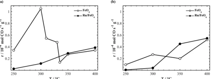
To establish the effect of Ru on FeOx, we compared the catalytic
activity of FeOx and Ru/FeOx for CO2:H2 ratios of 1:1 and 1:7 (Fig. 2(a)
and (b), respectively). In Fig. 2(a), the catalytic activity of FeOx reached
a maximum CO rate at 300 °C, followed by a lower CO rate at 335 °C which then increased with temperature. The catalytic activity asso-ciated with Ru/FeOx increased with temperature, overtaking the CO
rate of FeOx at ~ 330 °C. Increasing the reducing conditions to CO2:7H2
(Fig. 2(b)) results in a similar pattern for FeOx with a decrease in overall
catalytic activity, where the CO rate reached a maximum at 300 °C, decreased at 350 °C and then increased with temperature. Ru/FeOx
outperformed FeOx at ~ 325 °C and continued to do so up to 400 °C.
Our previous works show that free-standing Ru nanoparticles produce CH4 when used as a nanofilm deposited on YSZ and barium-zirconate
yttria (BZY) solid electrolytes [21,30]. Thus, when combined with FeOx
the methanation reaction is inhibited, causing the catalytic activity to be > 99% selective for CO.
C. Panaritis, et al. Electrochemistry Communications 119 (2020) 106824
The initial high reaction rate of monometallic FeOx is linked to the
existence of an Fe3O4 active phase at 300 °C, which is reduced to a
mixture of Fe3O4–FeO as the temperature is increased. In terms of Ru/
FeOx, the CO rate follows the same trend for both 1:1 and 1:7, which is
to increase as a function of temperature. The increased CO rate asso-ciated with Ru/FeOx is due to the synergetic effect between Ru and
FeOx, in which Ru has the ability to dissociate H2 into atomic H,
pro-viding the opportunity for a spillover onto the FeOx nanowires, thus
generating oxygen vacancies. FeOx acts as a catalyst for the adsorption
of CO2 and its subsequent cleavage into CO and O. The dissociated O is
used to fill the oxygen vacancies to repeat the process all over again [35]. Thus, for monometallic FeOx, all sites compete for the activation
of CO2 and H2, while the addition of Ru provides sites for H2
adsorp-tion.
3.3. Electrochemical promotion of Ru/FeOx
Given that the RWGS is an endothermic reaction, the electro-chemical promotion experiments were undertaken at 350 and 400 °C. Fig. 3(a) shows the transient response for an applied potential of 1.5 V at 350 °C with CO2:H2 = 1:1. Upon anodic polarization of the Ru/FeOx
catalyst, oxygen ions migrate from YSZ to the Ru/FeOx catalyst
elec-trode, resulting in a CO rate increase of up to 1.6 times with an ap-parent Faradaic efficiency Λ = 3. When the potential was interrupted, the CO rate returned to the initial O.C. rate value.
Cathodic polarization resulted in the migration of O2– from Ru/FeO
x
through YSZ to the Au counter electrode. Fig. 3(b) shows the rate re-sponse upon negative −1.5 V polarization, which led to a CO rate in-crease of 2.4 with Λ = 0.5. Under polarization for 2 h, the reaction rate
Fig. 1. STEM image of (a) a fresh colloidal solution of Ru clusters on Fe oxide nanowires and (b) spent Ru/FeOx on YSZ, where Ru is represented by the bright spots
gradually increased due to the reduction of FeOx, thus influencing the
adsorption of CO2 and subsequent dissociation into CO and O. After
current interruption the rate remained in a promoted state (γ = 2.3) and another 2 h were required for it to return to its less active FeOx
initial state. Thus, based on the EPOC rules established by Brosda et al. [36], both positive and negative polarization resulted in an increase in the CO rate corresponding to inverted volcano behaviour, associated with weak adsorption of the electron donor (H2) and acceptor (CO2) on
the catalyst surface [26].
The catalytic activity of Ru/FeOx with stoichiometric
(CO2:H2 = 1:1) and reducing (CO2:H2 = 1:7) gas compositions was
evaluated under galvanostatic conditions at 400 °C. Fig. 4(a) displays the catalytic response under stoichiometric conditions when 1 mA current is applied. The CO rate initially increased due to the oxidation of inactive FexC [21] – this stage lasts for ~ 9 min before it stabilizes in
a promoted state with ρ = 1.2 and Λ = 1.04. Once the current is in-terrupted, oxygen stored in the form of FeOx is made available for the
reaction, resulting in an increased reaction rate and a persistent EPOC value of γ = 1.6 for 1 h before it returns to the O.C. value. For an applied current of −1mA (Fig. 4(b)), after 1 h the CO rate increased with ρ = 1.2 and Λ = 0.6. When the current is interrupted at 2 h, the p- EPOC is γ = 1.4 and requires 30 min to return to the O.C. value.
Fig. 4(c) and (d) display the effect of reducing conditions (ratio of CO2:7H2) with applied currents of 1 and –1 mA, respectively. Fig. 4(c)
shows that positive current application leads to a constant increase in the CO rate with ρ = 1.4 and Λ = 2.2. Once current is interrupted at 3 h, there is p-EPOC (γ = 2.3) for 1 h before it returns to the O.C. value. This is similar behaviour to FeOx when used on its own at 400 °C for
CO2:H2 = 1:1 [21]. Fig. 4(d) displays the transient response under
negative current –1 mA, with a steady-state rate increase of 1.2 with a Λ value of 3.4. When the current is interrupted there is a slight p-EPOC (γ = 1.3), which lasts less than 5 min. The high potential response is due to the decrease in oxygen ion conductivity of YSZ after extended catalytic testing. Because oxygen ions act as sacrificial promoters during the EPOC experiments they are continuously consumed and not replaced due to the absence of oxygen in the reaction feed. This therefore leads to YSZ reduction and a decrease in its conductivity. Regeneration of the YSZ by exposing it to an oxygen atmosphere could be envisaged in practical applications.
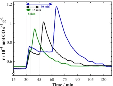
To elucidate the persistent EPOC effect occurring after current in-terruption at 400 °C, Ru/FeOx catalysts were polarized for 5, 15 and
30 min (see Fig. 5). Between each polarization, the open-circuit con-ditions were maintained for 2 h to ensure that the reaction rate is at a steady state. The slight initial increase in the CO rate occurring in all Fig. 2. Summary of the open-circuit catalytic rate on FeOx/YSZ [21] and Ru/FeOx/YSZ. The CO2:H2 ratios were (a) 1:1 and (b) 1:7.
Fig. 3. Transient reaction rate response of Ru/FeOx upon anodic (a) 1.5 V and cathodic (b) −1.5 V applied potential with CO2:H2 = 1:1 at 350 °C.
C. Panaritis, et al. Electrochemistry Communications 119 (2020) 106824
cases can be attributed to the oxidation of the FexC phase, which forms
in small amounts compared to monometallic FeOx [21] due to the
presence of Ru clusters which inhibit the formation of iron carbide. The longer the polarization time, the greater the storage of oxygen in FeOx,
resulting in a longer persistent EPOC once the current is interrupted. The corresponding persistent enhancement ratios are γ5min = 1.3,
γ15min = 1.35, and γ30min = 1.5. Similar conclusions were drawn for
monometallic FeOx, indicating that FeOx is an active component.
3.4. Effect of adding Ru
The addition of Ru to FeOx results in a dual functioning catalyst,
where Ru acts as a site for H2 adsorption and FeOx for CO2 adsorption
and dissociation [13,35]. The dissociation of H2 on Ru allows for
con-trolled H spillover onto FeOx. A metal–support interaction effect is
es-tablished between Ru clusters and FeOx which improves the CO rate at
increased temperature and results in new electrochemical behaviour. A direct comparison of Ru/FeOx and FeOx is shown in Figs. S1 and S2.
Although Ru influences the reaction rate, the FeOx prevails, ensuring
that the selectivity for CO is > 99%.
Compared with monometallic FeOx, the absence of an initial CO rate
increase once the anodic potential or current is applied indicates that a negligible amount of the FexC phase is formed in Ru/FeOx [21]. This is
further confirmed in the STEM image in Fig. 1(b), which shows that the proximity of Ru to the FeOx facets influences its oxidation state: Fe3O4
(111) is present near Ru, while FeO (111) and FeO (220) facets are exposed when Ru is absent. Furthermore, no carbon was detected on the STEM images, unlike the monometallic FeOx which forms a FeOx-C
core–shell structure [21]. This suggests that Ru inhibits the formation of iron carbide (FexC) by providing active sites for H2 adsorption and
dissociation, with H remaining on Ru, halting the reduction of FeOx into
FexC. Figure S3 compares the ρmax values of Ru/FeOx and FeOx, which
are associated with the formation of Fe carbide.
Ru/FeOx shows new p-EPOC behaviour compared to FeOx under
negative polarization, which indicates that the adsorption strength of H on Ru is weakened [29,37]. The weakening of the H bond and increase in CO2 activation on FeOx allow H to spillover from Ru to reduce FeOx
sites without both reactants competing for the same sites. FeOx is
Fig. 4. Transient rate responses of Ru/FeOx under galvanostatic conditions at 400 °C: left-hand side (a,c) + 1 mA and right-hand side (b,d) –1 mA. The gas
reduced to an active state during the polarization that persists after current interruption before returning to its initial less active FeOx state.
4. Conclusions
Our findings show that addition of Ru clusters to FeOx decreases the
formation of inactive FeCx, as confirmed in open-circuit and EPOC
ex-periments. Ru is shown to improve the redox reaction taking place on FeOx by adsorbing H2 and supplying H to FeOx, in the temperature
range 250–400 °C. A synergistic effect occurs between Ru and FeOx,
which enables FeOx to remain in an active state for the RWGS reaction
(> 99% selective to CO) and increase by 2.4 times during polarization. Overall, the addition of Ru nanoparticles in a two-step synthesis en-hances FeOx performance in redox reactions that can be applied to
in-dustrial scale applications where catalytic stability and susceptibility to carbide formation are crucial.
CRediT authorship contribution statement
Christopher Panaritis: Conceptualization, Methodology, Investigation, Data curation, Writing - original draft, Writing - review & editing, Visualization. Johnny Zgheib: Validation, Investigation.
Martin Couillard: Resources. Elena A. Baranova: Supervision, Data
curation, Writing - review & editing, Project administration, Funding acquisition.
Declaration of Competing Interest
The authors declare that they have no known competing financial interests or personal relationships that could have appeared to influ-ence the work reported in this paper.
Acknowledgments
This work was supported by the Natural Sciences and Engineering Research Council of Canada (NSERC) Discovery Grant (RGPIN05494).
Appendix A. Supplementary data
Supplementary data to this article can be found online at https:// doi.org/10.1016/j.elecom.2020.106824.
References
[1] W. Steffen, et al., Proc. Natl. Acad. Sci. USA 115 (2018) 8252–8259. [2] M.D. Porosoff, B. Yan, J.G. Chen, Energy Environ. Sci. 9 (2016) 62–73. [3] S. Saeidi, S. Najari, F. Fazlollahi, M.K. Nikoo, F. Sefidkon, J.J. Klemeš, L.L. Baxter,
Renew. Sustain. Energy Rev. 80 (2017) 1292–1311.
[4] C. Hepburn, E. Adlen, J. Beddington, E.A. Carter, S. Fuss, N. MacDowell, J.C. Minx, P. Smith, C.K. Williams, Nature 575 (2019) 87–97.
[5] D.C. Upham, A.R. Derk, S. Sharma, H. Metiu, E.W. McFarland, Catal, Sci. Technol. 5 (2015) 1783–1791.
[6] Y. Yan, Q. Wang, C. Jiang, Y. Yao, D. Lu, J. Zheng, Y. Dai, H. Wang, Y. Yang, J. Catal. 367 (2018) 194–205.
[7] K. Zhao, L. Wang, M. Calizzi, E. Moioli, A. Züttel, J. Phys. Chem. C 122 (2018) 20888–20893.
[8] J.H. Kwak, L. Kovarik, J. Szanyi, ACS Catal. 3 (2013) 2449–2455.
[9] C. Panaritis, M. Edake, M. Couillard, R. Einakchi, E.A. Baranova, J. CO2 Util. 26 (2018) 350–358.
[10] P. Vernoux, L. Lizarraga, M.N. Tsampas, F.M. Sapountzi, A. De Lucas-Consuegra, J.L. Valverde, S. Souentie, C.G. Vayenas, D. Tsiplakides, S. Balomenou, E.A. Baranova, Chem. Rev. 113 (2013) 8192–8260.
[11] K. Chang, H. Zhang, M.J. Cheng, Q. Lu, ACS Catal. 10 (2020) 613–631. [12] M. Boaro, S. Colussi, A. Trovarelli, Front. Chem. 7 (2019) 28. [13] S. Kattel, P. Liu, J.G. Chen, J. Am. Chem. Soc. 139 (2017) 9739–9754. [14] M. Wenzel, N.V.R. Aditya Dharanipragada, V.V. Galvita, H. Poelman, G.B. Marin,
L. Rihko-Struckmann, K. Sundmacher, J. CO2 Util. 17 (2017) 60–68. [15] D.H. Kim, S.W. Han, H.S. Yoon, Y.D. Kim, J. Ind. Eng. Chem. 23 (2014) 67–71. [16] J.A. Rodriguez, P. Liu, D.J. Stacchiola, S.D. Senanayake, M.G. White, J.G. Chen,
ACS Catal. 5 (2015) 6696–6706.
[17] M.V. Landau, N. Meiri, N. Utsis, R. Vidruk Nehemya, M. Herskowitz, Ind. Eng. Chem. Res. 56 (2017) 13334–13355.
[18] S.C. Lee, J.S. Kim, W.C. Shin, M.J. Choi, S.J. Choung, J. Mol. Catal. A Chem. 301 (2009) 98–105.
[19] R.W. Dorner, D.R. Hardy, F.W. Williams, H.D. Willauer, Energy Environ. Sci. 3 (2010) 884–890.
[20] J.A. Loiland, M.J. Wulfers, N.S. Marinkovic, R.F. Lobo, Catal. Sci. Technol. 6 (2016) 5267–5279.
[21] C. Panaritis, J. Zgheib, S.A.H. Ebrahim, M. Couillard, E.A. Baranova, Appl. Catal. B Environ. 269 (2020) 118826.
[22] C.G. Vayenas, S. Bebelis, C. Pliangos, S. Brosda, D. Tsiplakides, Electrochemical Activation of Catalysis: Promotion, Electrochemical Promotion, Metal-Support Interaction, Kluwer Academic/Plenum, New York, 2001.
[23] G.G. Vayenas, S. Bebelis, S. Ladas, Nature 343 (1990) 625–627.
[24] S. Bebelis, H. Karasali, C.G. Vayenas, J. Appl. Electrochem. 38 (2008) 1127–1133. [25] S. Bebelis, H. Karasali, C.G. Vayenas, Solid State Ionics 179 (2008) 1391–1395. [26] D. Theleritis, S. Souentie, A. Katsaounis, C.G. Vayenas, ACS Catal. 2 (2012)
770–780.
[27] I. Kalaitzidou, M. Makri, D. Theleritis, A. Katsaounis, C.G. Vayenas, Surf. Sci. 646 (2016) 194–203.
[28] A. Kotsiras, I. Kalaitzidou, D. Grigoriou, A. Symillidis, M. Makri, A. Katsaounis, C.G. Vayenas, Appl. Catal. B Environ. 232 (2018) 60–68.
[29] C. Panaritis, C. Michel, M. Couillard, E.A. Baranova, S.N. Steinmann, Electrochim. Acta 350 (2020) 136405.
[30] D. Zagoraios, C. Panaritis, A. Krassakopoulou, E.A. Baranova, A. Katsaounis, C.G. Vayenas, Appl. Catal. B Environ. 276 (2020) 119148.
[31] C. Falgairette, A. Jaccoud, G. Fóti, C. Comninellis, J. Appl. Electrochem. 38 (2008) 1075–1082.
[32] I.R. Gibson, G.P. Dransfield, J.T.S. Irvine, J. Mater. Sci. 33 (1998) 4297–4305. [33] B. Leszczynski, G.C. Hadjipanayis, A.A. El-Gendy, K. Załęski, Z. Śniadecki,
A. Musial, M. Jarek, S. Jurga, A. Skumiel, J. Magn. Magn. Mater. 416 (2016) 269–274.
[34] A. Lak, J. Dieckhoff, F. Ludwig, J.M. Scholtyssek, O. Goldmann, H. Lünsdorf, D. Eberbeck, A. Kornowski, M. Kraken, F.J. Litterst, K. Fiege, P. Mischnick, M. Schilling, Nanoscale. 5 (2013) 11447–11455.
[35] D. Zhang, J. Luo, J. Wang, X. Xiao, Y. Liu, W. Qi, D.S. Su, W. Chu, Chinese, J. Catal. 39 (2018) 157–166.
[36] S. Brosda, C.G. Vayenas, J. Wei, Appl. Catal. B Environ. 68 (2006) 109–124. [37] D. Theleritis, S. Souentie, A. Siokou, A. Katsaounis, C.G. Vayenas, ACS Catal. 2
(2012) 770–780.
Fig. 5. Transient rate response to application of 1 mA for 5, 15 and 30 min at
CO2:H2 = 1:7 and 400 °C.
C. Panaritis, et al. Electrochemistry Communications 119 (2020) 106824