CNC Router Modernization
By Aaron L. Doody
SUBMITTED TO THE DEPARTMENT OF MECHANICAL ENGINEERING IN PARTIAL FULFILLMENT OF THE REQUIREMENTS FOR THE DEGREE OF
BACHELOR OF SCIENCE IN MECHANICAL ENGINEERING AT THE
MASSACHUSETTS INSTITUTE OF TECHNOLOGY JUNE 2007
© 2007 MASSACHUSETTS INSTITUTE
OF TECHNOLOGY
Signature of Author:
SDepefient of Mec
cal Engineerin
May 11,.29
-e
9i-
V
d by:
-w David Wallace Associate Professor ____ Thesis Supervisor Accepted by: i MASSACH1JSFTm Ii.Srm yr OF TECHNOLOGYJUN
2 12007
LIBRARIES
ARCHIVES
Certified by: vCNC Router Modernization
by
Aaron L. Doody
Submitted to the Department of Mechanical Engineering on May 11, 2007 in partial fulfillment of the requirements for the Degree of Bachelor or Science in
Mechanical Engineering
ABSRACT
A large-format CNC router has been stored in the Pappalardo Laboratory wood shop for several years in an unusable state. A need assessment determined that it would be cost effective to bring the router online for use in the mechanical engineering curriculum. The router was cleaned and inspected; it was determined that the router was in sound mechanical condition. The stepper motors, control system, and power supply were also
functional, but the CNC interface software was outdated. To ensure the long term viability of the router as an effective teaching tool the most cost effective solution was to upgrade the motors, control system, and CNC interface software using a package
provided by the original supplier, Techno-Isel Inc. The motors, control system, and software were installed, bringing the router to a fully functional state.
Dust and ejected cuttings cause a safety hazard and cleanliness problem when operating the router. An enclosure was designed and installed in order to trap the majority of debris and reduce noise levels in the workspace, and a brief user guide has been compiled to ensure safe and effective usage.
Thesis Supervisor: David Wallace Title: Associate Professor
ACKNOWLEDGMENTS
I would like to thank the many people that helped me complete my thesis project, including
Professor David Wallace, for taking me on as his advisee and providing me with valuable support and funding throughout the project
Dick Fenner, Director of the Pappalardo Laboratory, for his tireless help in procuring materials and garnering support for the project
Table of Contents
Abstract
3
Acknowledgments
4
1. Introduction
6
1.1.Capabilities
7
1.2.Potential Uses
7
2. Techno-Isel Gantry III Router
10
2.1.Router Design and Specifications
10
2.2.Inspection and Evaluation
11
3. Router Upgrade
12
3.1.Hardware Upgrade Selection
13
3.2.User Interface Selection
16
3.3.Upgrade Cost
20
4. User Guide
21
4. 1.Preparation
21
4.1.1. Preparing the Router
21
4.1.2. Mounting a Part
22
4.1.3. Turning on the Router
22
4.2.The User Interface
23
4.2.1. Jogging the Router
23
4.2.2. Executing a Program
24
4.2.3. Setup Parameters
25
4.2.4. Defining Toolpaths
26
5.
Safety
27
6. Results
28
Appendices
Appendix A
-
Technical Education Solutions, 11c.
29
1. Intoduction
The Pappalardo Laboratory provides mechanical engineering students with access to a variety of machine tools used in core curriculum classes including 2.007 - Design and Manufacturing I and 2.009 - The Product Engineering Process. The machines that are currently available include computer numerically controlled (CNC) lathes, CNC routers, band saws, drill presses, a CNC water jet cutter, vacuum former, and welder. The laboratory also houses a small woodshop equipped with a table saw, miter saw, and an array of small belt and drum sanders, drill presses, and jigsaws.
A large-format CNC router has been stored in the wood shop for several years in an unusable state. The objective of this project is to evaluate the need for the router as a part of the undergraduate curriculum, to determine the costs associate with bringing the router online, and the additional fabrication capabilities that it would bring to the lab. Based upon the findings of the preliminary evaluation, the router will either be repaired or will be discarded from the lab to reclaim valuable floor space.
In the spring of 2002, mechanical engineering senior Cesar Espitia conducted a CNC router capabilities assessment for use in the undergraduate and graduate curriculum. He concluded that a tabletop CNC router would provide a valuable fabrication tool for use in the mechanical engineering curriculum. I have reevaluated Espitia's suggestions and reached a similar conclusion.
Several factors were considered when assessing the need for a CNC router as an addition to the repertoire of machine tools currently available. Factors identified included
machine capabilities, user-friendliness, safety, and cost.
Capabilities
The Techno-Isel CNC Router is a 3-axis machine that is useful for working materials including wood, rigid foams, composite, aluminum and plastic. The dimensions of the gantry table accommodate parts larger than any of the available 3-axis CNC milling machines in the Pappalardo Laboratory. The router provides 1250 by 1040 mm of planar travel (XY) and 356 mm in plunge depth (Z). The CNC waterjet cutter is most similar in scale but is only useful in cutting along the XY plane. A CNC router has the added benefit of the Z axis to form pockets and 3-dimensional contours.
Potential Uses
Within the mechanical engineering department there are a range of potential uses that have been identified. They include:
>
Creating precision, interlocking joints for wooden structures> Machining large, contoured molds for thermal form plastic components
>
Prototyping and design evaluationAnd because the router is a relatively simple and intuitive machine, it is likely that students will be able to use it safely and effectively with little additional training.
It may prove particularly valuable in the course 2.009 - The Product Design Process. In 2.009, teams of senior mechanical engineering students work together to design and build a functional alpha prototype of a product. The design process includes multiple iterations of prototyping, testing, and final production. The additional capabilities that the router provides will expand the scope of fabricable designs; teams may become more ambitious or creative if the router's capabilities are available. A router can also improve the
effectiveness of the prototyping phase by increasing the quality and consistency of prototyped parts, as well as reducing their time to manufacture. For more details on past cases in which a gantry router would have been useful, please refer to CNC Router Capabilities Assessment for Undergraduate and Graduate Mechanical Engineering Courses by Cesar Espitia, 2003.
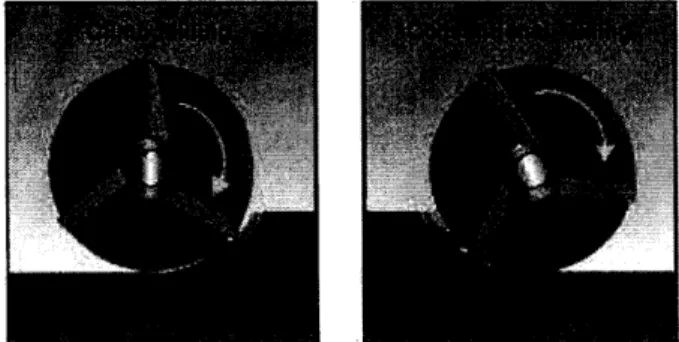
CNC routers are currently operated by other departments on campus, including two Techno-Isel LC Series routers used by the Department of Architecture's Digital Design Fabrication Group (DDFG). The students in DDFG have found novel applications of CNC router capabilities in their design projects. In addition to rapid prototyping and modeling, they have used the router to manufacture parts for full-scale construction projects. One noteworthy project was the Instant Cabin that was constructed entirely
glue. The precision cuts made by the CNC router made it possible to design interlocking components, as seen in Figure 1 and Figure 2.
assembled from interlocking plywood joists using friction to hold them together.
in place using a combination of dowel pins and dog bone style connectors.
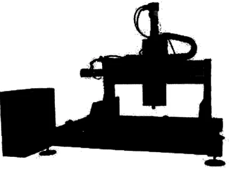
2. Techno-Isel Gantry III Router
Router Design and Specification
The Techno-Isel Gantry III (Model 130) router owned by the mechanical engineering department is similar to that in Figure 3. It is a gantry style table-top router with 3-axis of movement. A MAC200 Series control system drives a 150 oz-in stepper motor on each axis and is operated through a PC interface.
The drive system features an anti-backlash ball screw and nut, with a diameter of 16 mm and 5 mm pitch. Ball screws are used with great success in a wide range of machine design because they are low maintenance and are more tolerant of dust and debris than rack and pinion drives.
Figure 3: Gantry Router - The Techno-Isel Gantry III Table-Top Router
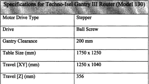
Table 1 lists the critical specifications of the Gantry III Model 130 router, including the table dimensions and range of travel.
Motor unve iype Drive Gantry Clearance Table Size (mm) Travel [XY] (mm) Travel [Z] (mm) 6tepper Ball Screw 200 mm 1750 x 1250 1250 x 1040 356
Table 1. Techno-Isel Gantry III (Model 130) Specifications
Inspection and Evaluation
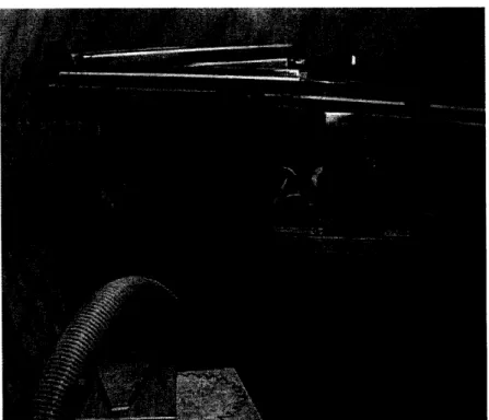
The router was unused between the fall 2003 and spring 2007, so cleaning, maintenance, and an inspection were needed to evaluate the state of the router. Figure 4 below shows the router as it was stored. The router is almost unrecognizable beneath a stack of
supplies stored on top of it.
The router is mounted on a six-legged table constructed of 1 5/8 inch strut channel members. A caster mounted at the base of each leg enables the table and gantry to be easily moved. Inspection of the table revealed that a central strut had come unfastened, allowing the two middle legs of the table to flair out. A pipe clamp was used to pull the middle legs back into their proper vertical positions and the strut was reattached.
Figure 4: Router in Storage - The Techo-Isel Router is barely distinguishable beneath a pile of building supplies
The condition of the gantry, including the ball screws and linear guides was evaluated. I manually moved all axis of the router throughout their full range of motion and
performed a brief visual inspection of the ball screws and linear tracks to ensure that they were in acceptable condition. All parts were found to be in good working order; there was no noticeable lash in any axis, the screws and bearings rotated smoothly, and the linear tracks were sound throughout.
The MAC200 SD controller was reconnected to each of the stepper motors and power was connected. The XY axis motors and control box seemed to be functional. I attempted to manually rotate the motors resistance from was felt.
When the MAC200 controller was connected the dedicated system PC all attempts to establish communications between the two failed. The PC system diagnostics indicated that both serial ports COM1 and COM2 were working. The Techno Interface Software output properties were checked several times. I attempted to establish a connection between the PC and MAC200 controller using both serial ports and several serial cables. After troubleshooting the problem I was unable to determine the cause of the
communication error.
3. Router Upgrade
Because the router table, gantry, and ball screws were in excellent condition, I focused on the software and control system as the limiting factors preventing the router from being used. The software and system PC were both outdated; the user interface operated in an MS-Dos environment and the PC ran windows 3.1.1 which is no longer supported by Microsoft. A software upgrade was necessary to ensure that the router would be
compatible with the current CAD/CAM packages available on campus. Simultaneously, the value of upgrading to a servo controlled system was investigated, and it was
determined most cost effective to upgrade the motors, control system and software as a single package. This strategy ensured compatibility between all system components.
Hardware Upgrade Selection
There are a wide variety of options available in the motion control industry. I had to decide whether to upgrade the existing control system or to switch to a servo controller.
The factory installed drive on the Techno-Isel router was a 3-axis stepper controller. The MAC200SD controller features true linear and circular interpolation during acceleration and steady-state operation, and uses a serial cable for bidirectional communication with the PC.
Stepper motors use multi-toothed laminated steel stator poles and a permanent magnet rotor to produce rotary motion. Standard hybrid stepper motor stators have 200 teeth, resulting in a step angle of 1.8 degrees per step. Because the motor must rotate in
discrete steps, the positioning of the rotor is essentially digital. The controller infers the position of the rotor using an open-loop control system that counts the number of steps sent to the motor. When used in open loop control schemes, stepper controllers can lose accuracy if the load torque exceeds the available motor torque because the open-loop system will not provide feedback if the motor fails to step. This is especially a problem at higher speeds, because stepper motors torque decreases with velocity. In order to prevent a loss in steps when operating at high speeds or under loads, a stepper motor should be rated for significantly larger loads than what are expected during normal operation.
Stepper motors do have some advantages. They are very reliable and low maintenance because they do not have brushes. They also have good holding torque, but because they
The driver used in the current system is an SD 15A Driver Card, which features a nominal output of 15 amps, and a maximum step rate of 10 kHz. It is a bipolar chopper drive -the most commonly used stepper drive in industrial applications. It uses two sets of
switching transistors to drive the motor with a single power supply, which results in high performance and efficiency.
Servo controlled motors use an optical encoder and closed loop feedback system to maintain a high degree of positional accuracy. There are several types of servo motors
available, including DC brush-type, DC brushless (sometimes called 'inside-out' motors because the permanent magnets are mounted to the rotor, and the windings comprise the
stator) which are higher performance, more thermally efficient, and low maintenance.
Although DC brush-type motors require some maintenance when used in industrial applications, they should be virtually maintenance free when used in an academic setting. Brushes typically need to be replaced after about 5000 hours of use, a threshold that can be reached in 7 months of heavy use, but will take decades to reach in an academic environment.
Servo controlled motors have many advantages over stepper motors. Because they use closed loop feedback, as stepper motor with an incremental encoder will maintain a high level of positional accuracy. A z-channel or indexer includes an extra pulse once per revolution to correct for any errors in incremental counting. The closed loop feedback
also ensures that the motor will draw the current required to maintain a desired path and velocity. Servo motors are faster and quieter than comparably sized stepper motors during operation. According to Techno-Isel literature, servo control motors can reduce operation time by 80% in many applications'.
Ultimately, servo motors were selected for use in the gantry retrofit upgrade because they have smooth, quiet operation, and provide a superior surface finish. And because servo motors are more widely used in the industry than stepper motors, it will be less time consuming and costly to get spare parts and have the motors repaired or serviced in the future.
User Interface Selection
The primary concern for implementation of the router in engineering classes is ease of use. Mechanical engineering students have limited time to become comfortable using the variety of machine tools available. Personal experience and conversations with fellow students indicate that ease of use is as important a factor when choosing a fabrication technique as machine capabilities and time constraints.
1. http://www.techno-isel.com/CNC_Routers/FACTS.htm#tableFACT (visited April 12, 2007)
The CNC router ran a user interface in Microsoft Windows 3.1.1, an outdated operating system no longer supported by Microsoft. The Techno CNC interface operated in an MS-DOS environment. The CAD/CAM software used on the machine was MasterCAM version 5.4, which is not backwards compatible with MasterCAM 8, the software
package that is now used in the mechanical engineering laboratories and courses including 2.008 -Design and Manufacturing II.
It was determined that the software package driving the router needed to be updated for a number of reasons; the operating system and MS-DOS environment are no longer
supported and are unfamiliar to students, the CAD/CAM package is not backwards compatible with current software, and the Techno CNC interface was unintuitive.
The selection of a new software package was made with three factors in mind - cost, user-friendliness, and compatibility. Techno-Isel Inc.'s CNC user interface was found to excel in all three areas. They provide free software upgrades, via download, for all of their CNC systems. The free software upgrades will ensure that the CNC Interface remains up-to-date to avoid CAD/CAM compatibility issues.
The Techno CNC Interface from build #377 is less powerful in its features and
capabilities than some more expensive options that were considered such as ArtCAM Pro by Delcam. However, the simplicity of the system leads to intuitive use and a quick
learning curve relative to more complicated software that is burdened by unnecessary features for a relatively simple 3-axis gantry router.
The features that I decided were unnecessary included control of more than 3-axis, aesthetic issues such as customizable skins or color schemes, workflow and toolpath optimization software, proprietary CAD packages, and 3D rendering. Toolpath optimization features are not needed because the primary use of the router will be for prototyping and one off production - small time savings in each operation are less critical in this case than they would be in a high-volume production line. The MIT mechanical engineering department already licenses and trains students on widely used CAD/CAM programs including Solidworks, ProE, and MasterCAM, so proprietary CAD/CAM programs are not needed as part of the router interface.
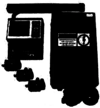
Standalone console-based control systems were also investigated as an interface for the router. I received quotes for two systems, the M-400 and M-39, manufactured by Centroid Corp. of Howard, PA. The console based systems were priced at 10,115 and 8,165 dollars respectively, which is about 200 percent the cost of the Techno-Isel upgrade package. Additionally, console style systems are not as flexible in their compatibility with external software packages and are generally less intuitive for students who are more familiar with PC interfaces. For these reasons, console based systems were not used in the router upgrade.
Figure 5: Standalone Interface - The Centroid M-400 console based CNC interface
The Techno-Isel Inc. servo upgrade package was selected for the following reasons:
>
Compatibility between the motors, controller and software>
Low cost> User friendly software interface
> Service and technical assistance are available through a vendor, Frank Gregorio of Technical Education Solutions, LLC. See Appendix A for contact information.
Upgrade Cost
In the course 2.009, student teams are each given a budget of 6,000 dollars to prototype and build a functional alpha prototype. The students use the budget to purchase materials for the project and the services of independent contractors including machine shops. Outside machine shops are used most often when in house fabrication equipment is insufficient to produce a part or when specialty services are necessary.
In the case of a CNC router, a typical outside machine shop may charge a one time setup fee of 25 to 50 dollars and an hourly rate of about 75 dollars per hour1'2. The price of an
upgrade, at 4,400 dollars, is equivalent to less than 80 hours of machining time at an outside machine shop. Therefore, it is more cost effective to bring the router online than to have 2.009 teams use the services of independent machine shops. In addition to saving money, direct access to the router has the advantage of decreasing the lead time needed to produce parts. Given the tight a schedule maintained in 2.009, a short lead time on part production is crucial.
There is also an intangible value associated with having the students use the equipment themselves rather than paying to have parts made by an independent contractor; hands on
experience is a goal of the class.
1. Ace Laser Supply and Engraving, CNC and Laser Cutting Services. Lowell, MA. Quoted $60/hr with a $25 dollar setup fee on their website
http://www.acelasersupply.com/About%20Us.html (visited May 8, 2007). 2. Sunshine Sign Company, Inc. North Grafton, MA. Quoted by telephone $85/hr
3.
USER GUIDE
-
TECHO-ISEL ROUTER
This user guide is intended to provide a brief introduction to use of the Techno-Isel CNC Router. For more detailed information please refer to the user's manual or the Techno
CNC Servo Gcode Interface from Build #377 for user tutorials.
Preparing the Router
Prior to using the router perform the following checks to ensure that it is safe to turn on the power.
o Check to see that there are no obstructions blocking the gantry tracks along the x-and y-axis
o Confirm that the control box is plugged into a three-prong grounded outlet
o Make sure that all cables are clear of heat and sharp objects, are untangled, and do not cross the work surface
o Remove loose items from the work surface
Mounting a Part
The workpiece should be fastened securely to the table prior to turning on power to the router. The gantry router is equipped with an aluminum T-slot table which provides numerous clamping options. The combination of fixed rails and cam style clamps that can be positioned on the table can secure most parts. If a particular part can not be
secured by these means, seek the help of a machinist or professor. Never use your hands to hold a part while using the router.
Figure 6: T-slot Mounting Table - The T-slot mounting table of the Techno-Isel Router, with a part fixed in position
Turning on the Router
The combination control box and power supply for the Techno-isel router is mounted beneath the gantry table. After securing the part to the table, flip the power switch to the on position. Green indicator lights will confirm that the control box is active. Turn on the PC located on the windowsill next to the router, and ensure that the bottom PCI card is connected to the control box. Open the Techno CNC Servo G-code Interface, either by double-clicking on the desktop icon or by clicking on the start button - all programs, and selecting Techno CNC Interface from the list. The main router operating screen will appear.
The spindle: speed and power are controlled independently by switches on the black router housing. The Porter-Cable spindle can be set to operate at 10,000, 13,000, 16,000,
19,000 or 21,000 rpm. As with any machining operation, tool diameter and the material being cut should be considered when a spindle speed is selected. In general, use a
conservative spindle speed for large diameter tools; they will have a higher velocity at the cutting surface than small diameter tools.
The User Interface
The most commonly used machining functions are available in the user interface main menu, shown in figure 7. The main menu contains three primary divisions - the jogging functions, the program execution functions, and a real time numerical location display.
the router
The bottom half of the screen is used for controlling the position of the gantry. Move the gantry either by clicking on the jog buttons on screen or by using the keyboard arrow keys
I$-4--
and plus-minus keys + -. Two jogging modes are available, Continuous and Step. Click the radio button next to each jogging mode to select it, or press the corresponding keyboard function key -[F9] for Continuous or [F8] to Step. Continuous jogging moves the gantry at a constant speed, set by the Jog Speed slider. Jog step moves the gantry in discrete increments; the step size of each increment is set by the JogStep slider.
The router controls also include four quick buttons, Home, Zero, Goto, and Tool. The Home button moves the gantry to a predetermined position known as 'machine home'. The Zero button is used to move one or all axis to their zero position. The Goto button can be used to move the gantry to a specified point or to the machine origin, which is the last zero position defined by the user. The Tool button opens a tool change operation window.
The Spindle OFF/ON/AUTO and Coolant OFF/ON/AUTO radio buttons will not be used - the spindle is controlled independently and the router is not equipped with a coolant system.
Executing a Program
The Techno CNC Interface allows users to import G-code from most CAD/CAM software packages, including MasterCAM.
To run a program, press the File button in the main menu. A browser will appear; locate the desired file on the computer and open it in the Techno CNC Interface. After a program has been imported, the g-code can be viewed and edited by clicking on the Edit button.
The Preview feature is used to view toolpaths before running the program. This function is helpful when editing code or as a check to ensure that the g-code has been imported properly. Use the buttons on the right edge of the preview window to change the viewing area; the toolpaths can be seen from the top, front, side, or isometric view. The left and right mouse buttons can be used to pan and rotate the view.
Prior to running a file, it must be Preprocess-ed. Click the Preprocess button - a progress bar will indicate the percentage of the program completed while displaying the corresponding g-code commands. When the preprocessing is complete, the progress bar will turn from red to green.
After the file has been preprocessed and the execution parameters set, the g-code can be executed. Press the Start button on the main menu or use the Start button on the remote
start stop box. Use the Pause buttons to pause a program and the Stop button to
terminate the program. In an emergency, press the red E-Stop button on the remote start stop box.
Setup Parameters
File execution parameters including feed rate for cutting on the x- and y-axis and plunging on the z-axis, as well as scale factors and tool offsets are set using the Setup button and its submenus.
Defining Toolpaths
It is important when defining tool paths that traditional milling is used instead of climb milling. Climb milling will result in poor cut quality and can also damage the router by causing excess vibration and stress on its components.
Figure 8: Milling - Climb milling versus conventional milling - avoid
climb milling when using the Techno-Isel Router
It is also advisable that finish cuts be made with the grain when routing wood, because wood may chip or splinter at the end of a cut when cutting perpendicular to the grain direction.
4. Safety Considerations
The router in the lab generates noise, dust, and projectile debris which can be harmful to the user. A machine enclosure has been designed to minimize the risk associated with each of these hazards. The enclosure is comprised of an acrylic top which enables ambient light in, while containing dust and debris. Clear, flexible vinyl sheet is used to cover the sides of the enclosure. The vinyl provides easy access to the table for loading and unloading parts, cleaning, and maintenance.
The safety enclosure does not supplant personal protective equipment. It is important to follow all of M.I.T's safety regulations. It is advisable to:
>
Wear safety goggles at all times while operating the router>
Check the material safety data sheet (MSDS) of the workpiece to ensure that airborne particulates do not pose a health risk>
Wear hearing protection if the noise level of the machine exceeds the Occupational Safety and Health Administration (OSHA) acceptable limits.6. Results
The upgraded components were procured from Techno-Isel Inc. an installed on the Gantry III router the week of May 7, 2007. The control system, motors, and software are fully functional as of May 9, 2007. The installation procedure included replacement of the motors, spacers, and motor couplings, installation of the interface software and a PCI card, and testing of the end of limit switches. A list of the new parts installed during the upgrade, as well as contact information for the sales engineer at Techno-Isel Inc. is available in appendix B.
Future work on the router will include completion of the router enclosure, the addition of articulated plastic cable carriers to extend cable life and prevent entanglement, and the fabrication of test parts to verify the router capabilities. The router enclosure, as of May
10th, has been structurally framed, but the top and side curtains have not been installed.
The success of this project will not be fully realized until fall 2007 when mechanical engineering students first have the opportunity to use the router to fabricate parts. To ensure that the router is utilized to its fullest capabilities, I recommend that at least one machinist become familiar with it, and that a full range of tooling is provided.
Apendix A
Contact information for Technical Education Solutions, the vendor that supports Techno-Isel Inc. in our region.
TECHNICAL
EDUCATI O N
SOLUTIONS, LLC
LINECARD
'we undersell and overdediver'
We are proud to offer genuine New England style service and we carry only those products that
meet those same high standards. Located throughout New England, our offices are staffed with professionals dedicated to delivering prompt and efficient service that you expect and deserve.
Technical Education Solutions PRODUCT AND SERVICES Technology Education Health Science Pre-Engineering
C.A.D. Software C.A.M. Software CNC Machines
Electronics 3-D Printers Manufacturing Technology
Hydraulics / Pneumatics Interactive Whiteboards Agri-Science
Automation / PLCs Family & Consumer Science A+,Network+,MOUS Courses
F.E.I.N #: 06-1526565 Website: www.teched.org
> 3D SYSTEMS, Inc (Rapid Prototyping)
InVision LD 3-D Printer - Affordable, desktop printer
InVision SR 3-D Printer -Leading 3-D printer for creating high quality pans at an affordable price InVision HR 3-D Printer - High resolution 3-D Printer for generating small and intricate parts
> NIDA CORPORATION
Electronics, PLC, Fiber Optics, Math, Physics, Chemistry, Automotive programs - CAI & Traditional > APPLIED TECHNOLOGIES
Health Occupation programs for Middle and High School, Agd-Science, A+, Network+, MOUS, MCSE Certification Courses and Tech Ed programs
> SOLIDWORKS
3D Mechanical Design CAD Software Solutions, including Finite Element Analysis with Motion
> SOLIDCAM
The Gold-Certified integrated CAM-engine for SolidWorks
) MASTERCAM
Multi-surface, up to 5 axis, Machining Software (Mill/Tum), Wire EDM and new Router release
> TECHNO-ISEL, INC.
CNC Routers/Mills, CNC Lathes (Wood & Metal), Automated Manufacturing Solutions
> DEPCO, LLC
Pre-Engineering, Career & Technology Education, Family & Consumer Science, & Agri-Science
[I
All programs have both middle school and high school levels NW> CHIEF ARCHITECT3d Architectural CAD Software > NUMONICS
Interactive Whiteboards ranging in size from 47" Diagonal to 77"' Diagonal
> E&L INSTRUMENTS / GLOBAL SPECIALTIES
Traditional ELECTRONICS training equipment & Low cost test equipment
www. teched.
org
64 BENZ STREET * ANSONIA, CT 06401-2648
Appendix B
-Part list and contact information for sales engineer, Tim O'Connor, who assisted in part selection for the upgrade
Techno CNC
2 JeAQkn TpIe-, S.ew Hsy&s fak, NY 1m40
FP BWDID•3 For 51&36-B-257
Tim O'onnor
Sales
Engineer
ox
eatSDae: 04-184M2. Fk amo w mid Jbr 30 ad Quote prepared for: LD BERVO UPGRADE
DART MUMBER QTY DESCRIPTIOND
1 3-Axis LP Servo Control
Includes: Servo Control in enclosure with power Gcode Interface.
110V power source.
Package.
amplifier card mounted supply, pci card, and
H22600X0243600-L HZ26001KO243610-L HZ2600N0242600-S HB1700• 015.5-LC B26T5-STRSTDLC HZ CAT SOFTCD
cmputer Requirements not included with machine purchase: Dentium III / Celeron 600 Nha or better with fall DCI Slat
to handle 6" long card.
Note: Cables not included. 2 different lengths
available (15ft, 2fti)
2 XY Motor assembly for LD Electronics.
For use on Standard LC Electronics
For Gantry III systems a spacer kit is required per axis D/N:HZZ600IO24a600-S 1 Z Brake Motor assembly for LD Electronics.
For use on Standard LC Electronics
For Gantry III systems a spacer kit is required per axis D/K:EZE6OOM246-00-S
3 Spacer kit for LC Series motors
S Servo Motor and Encoder Cable pair for LD Electronics
only. (15 foot length)
1 Start/StoplE-Stop remote box for use on LC/LD Series
servo controller with Windows XPD or 2000
1 Software CD for Servo Windows GCode Interface. Includes DD! formatted manuals.