Coded Still Image Transmission Over Very Slow Fading
Channels
by
William Glenn Zeng
Submitted to the Department of Electrical Engineering and Computer Science in partial fulfillment of the requirements for the degrees of
Bachelor of Science and
Master of Science at the
MASSACHUSETTS INSTITUTE OF TECHNOLOGY February 1995
@ William Glenn Zeng, MCMXCV. All rights reserved.
The author hereby grants to MIT permission to reproduce and distribute publicly paper and electronic copies of this thesis document in whole or in part, and to grant
others the right to do so.
Author... ...-...
Deparirent of Electrical Engineering and Computer Science
-A . -. January 30, 1995
Certified by..
Mitchell D.Trott Assistant Professor of Electrical Engineering Thesis Supervisor Certified by
Member of Technical Staff,
Vijitha Weerackody AT&T Bell Laboratories Thesis Supervisor Accepted by ... .- w. F.. w, .0. .".X . ...
... Frederic R. Morgenthaler
Chai man, I l jI n ittee on Graduate Students ApR T1P3 lo; Enlv
/APP 1
3]
iqq•En,
... . V V. .-% . - k. ... . . . " ...Coded Still Image Transmission Over Very Slow Fading
Channels
by
William Glenn Zeng
Submitted to the Department of Electrical Engineering and Computer Science on January 30, 1995, in partial fulfillment of the
requirements for the degrees of Bachelor of Science
and
Master of Science
Abstract
Coded still image transmission over very slow fading channels is difficult because transmission errors on these channels occur in long bursts and the raw bit error rates are unacceptably high. In JPEG, the new international standard for color still image compression, certain markers are extremely sensitive to transmission errors such that a single bit error may cause the entire image to be lost. This thesis develops novel transmit antenna diversity techniques and applies these diversity techniques in two transmission protocols for JPEG coded still images on very slow fading channels. The first protocol uses a feedback channel to request retransmission of the erroneous data and to inform the transmitter to use a different transmit antenna when the current diversity branch is detected in a deep fade. An induced fast fading diversity technique that can effectively provide time diversity in slow fading environments is used in the second protocol. This protocol operates in a forward error correction mode in the absence of a feedback channel. Both protocols are shown to have significant performance improvements over the corresponding protocols without diversity.
Thesis Supervisor: Mitchell D.Trott
Title: Assistant Professor of Electrical Engineering
Thesis Supervisor: Vijitha Weerackody
Title: Member of Technical Staff, AT&T Bell Laboratories
Acknowledgments
First and foremost, I wish to thank Dr. Vijitha Weerackody at AT&T Bell Labora-tories and Prof. Trott at MIT for their guidance and support throughout this study.
I have had the good fortune to work with and learn from many members of AT&T Bell Laboratories during my co-op experiences at the Laboratories. I am especially indebted to Dr. Jakub Segen at Holmdel, Dr. Jim Snyder and Dr. Thrasos Pappas at Murray Hill. I also owe a great debt to Dr. Emerald Chung for developing the network resources sharing environment which enabled me to run the incredibly large amount of software simulations on nearly one hundred SGI workstations at the In-formation Principles Research Center. Dr. Hui-Ling Lou and Dr. Nambi Seshadri
provided valuable comments on early versions of the manuscript.
During my years at MIT, the encouragement, support, and understanding I have re-ceived from Prof. Min-Chang Lee are deeply appreciated. I also owe much gratitude to Dr. Satoshi Takahashi for his personal friendship during the prolonged period of writing this thesis.
Last but certainly not least, I wish to thank my family for its support and patience during the years I have spent far away from home in pursuing my education. I have promised them that I would spend more time closer to home after I graduated. I do not know if that will materialize soon.
Finally, this thesis is dedicated to my father. I never had the good fortune of meeting him because he passed away when I was little. But his scholarly excellence has always inspired me to follow his footsteps and hope one day to exceed his achievements. This thesis is also dedicated to the loving memory of my grandparents.
Contents
1 Introduction
1.1 Thesis Overview ...
2 The Indoor Radio Channel
2.1 Multipath Interference . ... 2.2 Rayleigh Fading ...
3 On Error Control Protocols 3.1 Error Control Protocols ... 3.2 Average Frame Erasure Rate...
3.2.1 Background ... 3.2.2 Very Fast Fading ... 3.2.3 Very Slow Fading ...
3.2.4 Interpretation of Results . . . 3.3 A Simple ARQ Protocol ...
3.3.1 Channel Throughput Analysis 3.4 Imperfect Feedback Channel... 3.5 Memory ARQ . . . . 3.6 Concluding Remarks ...
4 Concerning JPEG Coded Still Images 4.1 Division of JPEG Coded Image Data .
4.2 Effects of Transmission Errors ...
4.3 Implications for Transmission Protocol Design . ...
14 . . . . 14 . . . . 16 . . . . 17 . . . . 18 . . . . 19 . . . . 19 . . . . 2 0 . . . . . 2 1 . . . . 2 3 . . . . . 26 . . . . 28
5 Switched Transmit Antenna With Feedback Protocol 5.1 4-DPSK and Convolutional Codes ...
5.1.1 4-D PSK . . . . 5.1.2 Convolutional Coding and Block Interleaving. . 5.2 Switched Transmit Antenna with Feedback . . . . 5.2.1 Principles of Operation . . . . 5.2.2 Performance Comparisons . . . . 5.3 Sum m ary . . . .
6 Repetition-Type FEC Protocol 6.1 Simple Scheme ...
6.2 Induced Fast Fading Diversity ... 6.2.1 Principles of Operation ... 6.2.2 BER Improvement ...
6.2.3 Obtaining Diversity Order M with M 6.3 Improved Repetition-Type FEC Schemes . .
Transmit Antennas
7 Laboratory Implementation
7.1 Communication System Hardware ...
7.2 Coded Still Image Transmission Protocol . . . . 7.3 Experim ental Results . . . .
8 Conclusion 35 ... . . 35 ... 36 ... . . 37 . . . . . 40 . . . . . 40 . . . . . 44 . . . . . 52 75 75 78 79 86
Chapter 1
Introduction
Recent interests in indoor radio communications are closely related to the exciting developments in today's telecommunications industry. The industry is in the midst of very active research, development, and deployment of a whole host of wireless communication services and products ranging from paging, cellular telephony, and indoor wireless local area networks to more sophisticated wireless networks collectively known as Personal Communication Networks (PCN). With the full deployment of PCN, a user can initiate and receive phone calls, request and send data, transmit and process images, and perform a variety of other functions from his lightweight wireless communication unit, and be able to do so from anywhere, anytime [1]-[3]. Since the users of these communication services spend a large proportion of their time at numerous indoor facilities, any successful PCN implementation must have an important component which provides voice, image, video, and data to people indoors [4].
The communication services and products envisioned above pose challenging ques-tions. Data communication on indoor radio channels is difficult due to the slow fading characteristics of these channels. The received signal strength on these channels is slowly time-varying with a large dynamic range (17-60 dB) [4][5]. A receiver located in a deep fade will remain there for an extended period of time to cause long bursts of data errors. For data applications such as image and video, the required bit error rates are very low (10 5 or less). It will be difficult, if not impractical, to achieve
the required low bit error rates without error control. Given the low bit error rate requirements, the chosen error control scheme must also meet the delay constraints of the intended applications. Sophisticated coding and modulation techniques, ad-vanced error control schemes, novel antenna diversity concepts are required to achieve reliable communication over these very slow fading channels.
1.1
Thesis Overview
This thesis describes two transmission protocols for JPEG coded still images on very slow fading radio channels. Both protocols are extensively investigated with computer simulations and supported by analytical studies and laboratory experiments.
Chapter 2 briefly describes fading channels. A statistical model is selected for mathematical analysis and simulations. Several relevant results from the literature are used to illustrate the deleterious effects of fading on data communications.
Chapter 3 introduces some basic automatic repeat request (ARQ) and forward er-ror correction (FEC) concepts. Several simple erer-ror control schemes are implemented in software to highlight some performance issues.
Chapter 4 formulates the problems facing JPEG coded still image transmission over very slow fading channels by presenting the JPEG coding structures and the consequences of transmission errors on the received image quality. The major conclu-sions are that a small percentage of the JPEG compressed still image data contains the important information that must be received error-free when possible. We label this Type-I information. It suffice to say at this point that the Type-I information is so important that a single transmission error may cause the entire image to be lost. The rest of the JPEG coded still image data, the Type-II information by our definition, should be received with the lowest bit error rate possible but transmission errors on this information are not as disastrous as transmission errors on the impor-tant Type-I information. The presentation makes a strong case for the chosen error
control schemes to be studied and implemented in subsequent chapters.
tech-niques are extensively studied for reducing the detrimental effects of fading on mul-tipath fading radio channels. In particular, a novel switched transmit antenna with feedback diversity technique is treated in Chapter 5. This technique is applied to an efficient protocol for JPEG coded still image transmission over very slow fading channels. In this protocol, a feedback channel is provided to request retransmission on erroneous data packets and to request the transmitter to use a different transmit antenna when the current diversity branch is detected in a deep fade. The impor-tant Type-I information is transmitted with a Stop-and-Wait ARQ protocol while the Type-II information is transmitted with a FEC code in the time slots left idle by the Stop-and-Wait ARQ protocol. The protocol can be efficiently implemented without allocating extra bandwidth to transmit the switch requests or performing the explicit received signal strength measurement as in a conventional switched transmit antenna with feedback scheme. This transmission protocol is shown to have significant per-formance gain on very slow fading channels.
For practical applications where a feedback channel is not available, a FEC proto-col using an induced fast fading diversity technique that can effectively provide time diversity in the slow fading environments is presented in Chapter 6. This protocol multiplexes the transmissions of the Type-I and Type-II information. The Type-I information is allowed for multiple transmissions as in a repetition code and then appropriately combined at the receiver. The Type-II information is transmitted once with a convolutional code. The fast fading characteristics deliberately induced by this diversity technique increase the correcting capability of the channel code drastically and consequently improve the transmission reliability.
Chapter 7 provides laboratory implementation details of the JPEG coded still image transmission protocol. Experimental results are provided to verify the theoret-ical analysis and software simulation results in the early chapters. A summary and
Chapter 2
The Indoor Radio Channel
This chapter very briefly introduces the indoor radio channel. Multipath interference is explained first. Two models for describing the statistics of the received signal are then discussed. Finally, several consequences of Rayleigh fading are collected here to illustrate the detrimental effects of fading on data communication qualities over these channels.
2.1
Multipath Interference
In a typical indoor radio environment, the portable receiver does not receive just one copy of the transmitted signal. Rather, due to scattering and reflection, the transmitted signal reaches the receiver via multiple paths with different time delays, amplitudes, and phases. The received signal is the sum of these component waves. Mathematically, suppose a unit amplitude continuous wave signal
x(t) = Re{ej2, ,t} = cos27rfct (2.1)
of frequency
fc
is transmitted. The received signal is Ny(t)
=
Ref{E[ai(t)e
(
t)jkzi
e3j•
27ft},
(2.2)
where ai(t), zi, Oi(t) = qi(t) + kzi are the random time-varying amplitude, path length, and phase of the iZh component wave, respectively. N is the number of com-ponents. The constant k = 27/A is the wave number, while q5(t) depends on the time variation of the channel. For electromagnetic wave propagating at the speed of light c, the path length zi is related to the arrival time -i by zi = cTi. Much effort in recent measurement and modeling of the indoor radio channel is devoted to obtaining statistical models for these random time-varying quantities
[4][5].
Because A at mi-crowave frequency is very short, a small change in zi causes a large phase shift in Oi(t). These rapid time variations in the phases{0
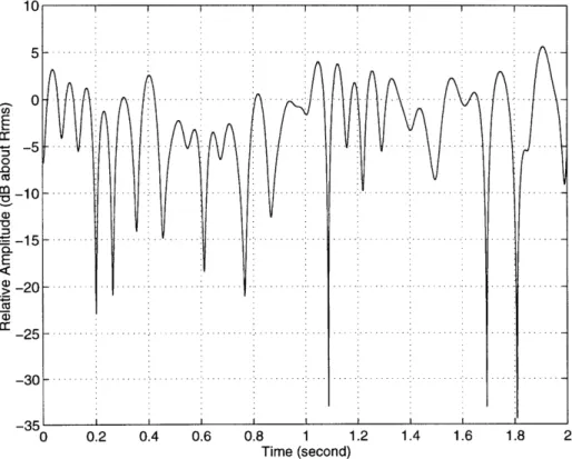
2(t)} are responsible for the constructive or destructive interference of the component waves. A typical interference pattern resulting from multipath fading is depicted in Fig. 2-1. This plot was generated in software by using a technique described by Jakes [9, pp. 70-76] with v = 1 km/hr andfC
= 900 MHz, where v is the mobile speed. The meaning of these parameters will become clear in later discussions.C') 0 0 Cu E C, CO Time (second)
2.2
Rayleigh Fading
When considering statistical models for the small scale path amplitude distributions, usually two models apply depending on the presence or absence of a line-of-sight component. For indoor environments, a line-of-sight component may be present. But this need not be the case. In our laboratory experiments to be described in Chapter 7, the transmitter and receiver are located separately in two adjacent rooms with metallic walls. The propagation path is further obstructed by typical laboratory equipment and office furniture in these two rooms. The received signal comes from scattering via the ceiling, floor, walls, and furniture. A direct line-of-sight component does not exist.
The Rayleigh fading model is widely accepted for narrowband multipath fading channel without a strong line-of-sight component. The reason is because the average amplitudes of the component waves are statistically independent and identically dis-tributed. When the received signal in (2.2) is considered, two quadrature components I and
Q
exist, N I = ai(t) cos 0i (2.3) i=1 N Q = E ai(t)sin Oi (2.4) i=1By applying the central limit theorem, it follows that these components are Gaussian distributed. Hence the amplitude of the received signal, r = V/I2 +
Q
2 is describedby a Rayleigh distribution, and the phase 0 = tan-1 (Q/I) is uniformly distributed in
(0, 27]:
r T2
PR(r) =
a
2 exp{-2a
2 } r > 0, (2.5)1
pe(O) = 27 0 < 0 < 27r, (2.6)
where 20-2 is the second moment of the Rayleigh distribution.
components. The severity of fading is reduced in comparison to the Rayleigh fading case. The mathematics, however, becomes more difficult. For example, the prob-ability distribution of the amplitude, appropriately called the Ricean distribution, contains a zero-order modified Bessel function of the first kind,
PR
(r)
=
r exp{-
2+}20(2 2)r > 0,
(2.7)
where lo(.) is a zero-order modified Bessel function of the first kind, and u is the magnitude of the strong line-of-sight component.
For mathematical analysis, we use the Rayleigh model because it is analytically more tractable and the results obtained with this model can at least be thought of as the lower bounds on system performance when a line-of-sight component does become available at certain instances. In fact, Rayleigh fading is a special case of the Ricean fading model when the line-of-sight component is removed. The Ricean distribution in (2.7) becomes the Rayleigh distribution in (2.5) when the amplitude of the line-of-sight component goes to zero [4].
Once the Rayleigh model is accepted, several well-known consequences
[4]-[10]
should be discussed. In the presence of Rayleigh fading, as a receiver moves in a spatial field-strength variation profile such as shown in Fig. 2-1, while unusually strong signals (5 dB above rms) are extremely rare, very weak signals (10 dB below
rms) are common. It can be easily shown
[9]
that the received signal is 10 dB below the rmrns signal strength for 10% of the time, whereas the signal is 5 dB above therms signal strength for less than 1% of the time.
Another way to characterize fading is by the temporal, rather than spatial, cor-relation properties of the received signal. Referring to Fig. 2-1 once again, given the signal is in a deep fade at some time instant, with very high probability the signal is also in a deep fade a short duration away. How quickly the signal at different time instances are decorrelated can be measured by the coherence time of the channel.
This quantity is approximately given by [12, p123] 1
0
2f(2.8)
,
2w fD
where fD = v/A = v/(c/fc) is the Doppler frequency associated with the relative motion v between the transmitter and the receiver. This apparent frequency shift could also be contributed by the changes in the channel medium such as people or equipment moving about the transmitter and receiver. For indoor radio channels, this time variation is very small. Therefore, r, for indoor radio channels is very large in comparison to the data signaling intervals. Such channels are best characterized as very slow fading. To give a particular example, suppose the channel variation in the indoor radio channel is represented by an equivalent speed of 1 km/hr. At 900 MHz carrier frequency and a data rate of 10 kbits/sec, T- is the equivalent of 2000 bit
durations.
Finally, as another consequence of Rayleigh fading, the average bit error rate (BER) of an uncoded system falls off only inversely with the signal-to-noise ratio (SNR) for large SNR values. In contrast, the same modulation scheme in the pres-ence of additive white Gaussian noise (AWGN) alone gives a BER that decreases exponentially with increasing SNR.
Chapter 3
On Error Control Protocols
The preceding chapter highlighted the severe limitations imposed on channel quality by Rayleigh fading. This chapter investigates several rudimentary error control pro-tocols on fading channels. It is the purpose of the current chapter to interpret some well-known results and clarify certain relationships between physical assumptions and mathematical derivations.
Several classes of error control protocols are introduced in Section 3.1. The average frame erasure rate, a quantity closely related to the throughput efficiency of ARQ protocols, is computed for the very slow and very fast fading channels in Section 3.2. The fundamental differences between very slow and very fast fading channels are then discussed. A simple ARQ protocol is analyzed in Section 3.3. In Section 3.4, the effects of an imperfect feedback channel on the channel throughput efficiency of ARQ protocols are illustrated. A very simple technique for improving the efficiency of ARQ protocols using code-combine decoding [29]-[32] is presented in Section 3.5. Section 3.6 concludes this chapter.
3.1
Error Control Protocols
In this section we summarize some known error control protocols. Automatic repeat request
(ARQ),
forward error correction (FEC), and hybrid ARQ error control proto-cols are commonly used to achieve reliable data communication. ARQ protoproto-cols usefeedback channels to request retransmission of erroneous data packets. FEC proto-cols operate in a broadcast mode without feedback channels and use powerful channel codes to correct transmission errors. ARQ protocols tend to be more reliable, but less efficient than FEC protocols. Hybrid ARQ protocols combine both features of FEC and ARQ.
The simplest ARQ protocol is Stop-and-Wait [13]. The transmitter appends par-ity check bits to the data stream to enable the receiver to detect errors. Following each transmission, the transmitter waits for an acknowledgment from the receiver. If no error has been detected, the received packet is delivered to the data sink and a positive acknowledgment is sent back to the transmitter. If at least one error is detected in the received packet, the receiver discards the packet and a negative ac-knowledgment is sent to the transmitter for retransmission of the erroneously received packet. The transmitter sends a new packet when a positive acknowledgment is re-ceived; otherwise, it retransmits the same data packet. A timer at the transmitter is activated when a packet is sent. If the acknowledgment is lost in the reverse link or arrives after the time-out period, a time-out mechanism is invoked to retransmit the same packet [14, pp. 64-86], [15, pp. 180-187].
The next two protocols are continuous protocols, whereby data packets are sent from the transmitter to the receiver continuously. In Go-Back-N [13], a negative acknowledgment causes the transmitter to go back to the negatively acknowledged packet and start transmitting from there. All packets following this erroneous packet are retransmitted even if some may already have been correctly received while the negative acknowledgment was being transmitted on the feedback channel. By con-trast, in Selective-Repeat [13], only the incorrectly received packets are retransmitted. Because of this selective retransmission of erroneous data packets, packets may be re-ceived out of sequence in a Selective-Repeat ARQ protocol. A theoretically infinite buffer is needed at the receiver to restore the proper ordering of the received packets before releasing them to the data sink. A time-out mechanism as described above is also needed for practical implementation of these continuous protocols.
number of information bits successfully accepted by the receiver to the total number of bits that could be transmitted per unit time [13], changes with the channel condition. Regardless of the throughput efficiency, ARQ protocols are extremely reliable with the appropriate choice of error detection codes.
On the other hand, FEC protocols do not use feedback channels. The transmitter introduces redundancy into the data stream to allow the receiver to correct errors and then deliver the decoded data block to the data sink, although some of the decoded data blocks may contain uncorrectable errors. Since the probability of uncorrectable error is higher than the probability of undetectable error, pure FEC protocols tend
to be less reliable than ARQ protocols.
Finally, hybrid ARQ schemes combine both features of FEC and ARQ [13]. The FEC subsystem is used to increase the throughput efficiency by reducing the number of retransmissions. When the feedback channel and error detection are perfect, all residual errors that cannot be corrected by the FEC subsystem are corrected by retransmissions. Hybrid ARQ schemes can be further classified into I and type-II. In a type-I hybrid ARQ scheme, the data blocks are coded for both error detection and correction. The resulting low code rate becomes inefficient when the channel condition is good. In a type-II scheme, the initial transmission is coded for error detection only and parity bits for error correction are transmitted only when necessary [13].
3.2
Average Frame Erasure Rate
ARQ protocols are based on the transmission of blocks of N sequential bits. Without error correction, one transmission error within a frame is sufficient to cause the entire frame to be rejected by the receiver. Frames are accepted when no error has been detected. Hence, the average frame erasure rate (FER), defined as the probability of any received frame chosen at random contains one or more errors, is directly related to the throughput efficiency of any ARQ protocol. In fact, if we redefine the throughput efficiency of an ARQ protocol as the ratio of the number of successfully delivered
data frames to the total number of transmitted frames on a channel, the average FER is precisely one minus the throughput. The latter definition is called the channel throughput to distinguish it from the overall throughput [16]. The overall throughput includes factors such as the code rate, stuffed bits for code synchronization, and parity check bits. Except for hybrid ARQ schemes, these are mere constant factors and can be easily incorporated into the final analysis when desired.
It would be desirable to obtain FER expressions in terms of the fading rates, but this turns out to be an extremely difficult problem due to bit error correlations on Rayleigh fading channels. Therefore we only look at two limiting cases: very fast fading and very slow fading.
3.2.1
Background
The bit error probabilities of several common binary modulation schemes in the pres-ence of additive white Gaussian noise (AWGN) are given by the formulas [18]
Sexp(- 1y) NCFSK, 1 exp(-7) DPSK,
Pb
7
2(3.1)
1 erfc(~ ) coherent FSK, 1 1 erfc(vf) coherent PSK,where 7 is the SNR value and erfc(.) is the complementary error function,
erfc(x) = e-t dt . (3.2)
Because bit errors are statistically independent on AWGN channels, with t bit error correction, the FER, Pw(7Y), is
t N
Py(7) = 1 -
>
Pb(7)'[1
-
Pb(7)]
N- i,
(3.3)
i=0 i
where N is the frame size measured in bits. The notation in (3.3) is such that P(7)) does not necessary mean there is only one 7 value for the entire packet of size N.
There may be several - values in a packet duration, as is the case in the fast fading limits.
Data transmission over Rayleigh fading channels presents a completely different picture. One of the fundamental differences between AWGN channels and Rayleigh fading channels is that the former is characterized by a steady signal strength re-ception and the latter by a fluctuating signal strength rere-ception [20]. The received time-varying signal strength is statistically described by a chi-square distribution with 2 degrees of freedom [18]
Pr(7) = exp(-_) , (3.4)
where F is the average SNR. In this case, BER and FER are derived in the average sense, where the average is taken over the instantaneous received SNR, 7Y. To calculate the average BER, we assume the effect of fading over one bit duration is effectively constant, although varying over a long succession of such bit signaling intervals [19]. For noncoherent frequency shift keying (NCFSK), the average bit error rate is given by
(Pb7)) = P(7)Pr(7)d = 21 (/2 + ) (3.5)
b10rI~ 2 1 +17/2
These ideas are extended in the following subsections to compute the average FER. It is noted here that for mathematical analysis, coherent modulation is difficult because of the complex formulas. For differential phase shift keying (DPSK), the formula appears harmless, but because differential encoding and decoding can lead to double errors which are not independent, unless sufficient interleaving is used to decorrelate these double errors, the analysis developed below does not apply to DPSK [20]. Hence, in order to make the mathematical derivations tractable, we carry out the analysis for NCFSK only.
3.2.2
Very Fast Fading
When the fading is very fast in comparison to the data symbol unit, bit errors for each symbol occur independently. This statistical independence between bit errors makes the average FER computation trivial. The result is simply obtained by replacing
Pb(cy) in (3.3) with (Pb(y)): (Pw (y))
N
N
= 1 - (Pb(7))[1 -(Pb(7))] N -i i=0i
N
N 1 2 1i=2(i
1
+
r/2)ll 2(1
+
r/2)
i=O Z)
(3.6)3.2.3
Very Slow Fading
In the very slow fading case, we assume the signal strength is constant over a block of N bits, but it varies from block to block. In essence, the entire block is treated like a single bit in the average bit error rate computations:
00
o Pw("y)Pr(7)d-t00
t
N
=
0{1
-
i=0N
i)
P
-
b
)]N-i}Pr(-)dy
tN 1ooN
=1
- Pb(7)[1 - Pb(7)l N-Pr(7y)d"yi=o i )
t N
oo1-
N - i
=e1 -- e (-1/2) i=o i T k=o kt
N-iN
N-i12
=
1
-
1
(-)N
i+
k )I
i=0 k=0 i (k2
(i + k)
-
k(
1d7
'+2 *3.2.4
Interpretation of Results
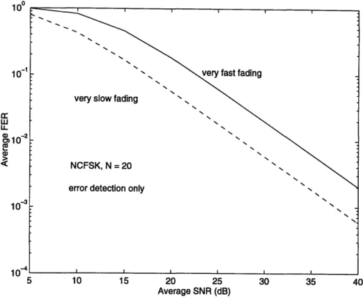
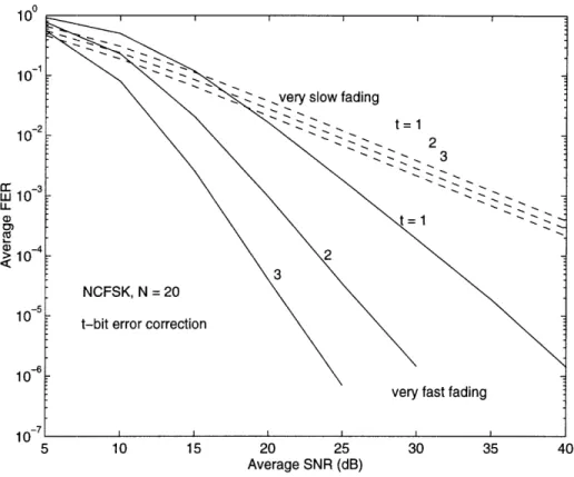
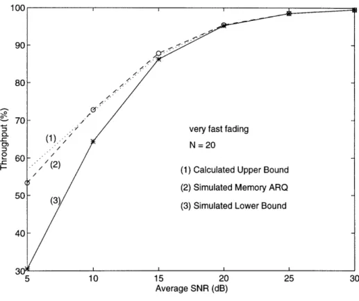
Calculated results for packet size N = 20 are shown in Fig. 3-1 and Fig. 3-2 for several values of t bit correction. Without error correction (Fig. 3-1), the average FER is higher at faster fading rates. This is because for both the very fast and very slow fading cases, the average BER is the same; but errors occur in bursts in the slow fading case. The same average number of errors distributed more uniformly in time causes a higher average FER for the fast fading case. This is a well-known
(P(Q))
1u 10 LLU 4) -10 C0 a)10 10-5 10 15 20 25 30 35 40 5 10 15 20 25 30 35 40 Average SNR (dB)
Figure 3-1: Average FER Performance without Error Correction
result and is presented in various forms in [21]-[25]. With error correction (Fig. 3-2), the correcting power of the FEC code is enhanced by interleaving or the inherent randomness on the channel at fast fading rates. Hence, the average BER decreases at higher fading rates to give a correspondingly lower average FER. A plot similar to Fig. 3-2 for DPSK with interleaving is shown in reference [21].
These two figures illustrate clearly the two competing effects on average FER: without error correction, the average FER is higher at faster fading rates; with error correction, burst errors at lower fading rates reduce the error correction capability of the channel code to result in higher average FER. A clear understanding of these issues is critical in designing error control protocols.
3.3
A Simple ARQ Protocol
This section analyzes a simple Stop-and-Wait ARQ protocol. This protocol has the unique feature that consecutive transmissions of data packets are separated far enough
LU
LL
a,
5 10 15 20 25 30 35 40 Average SNR (dB)
Figure 3-2: Average FER Performance with Error Correction
apart in time such that the fading processes among these packet signaling intervals are statistically independent. The channel throughput efficiency is obtained analyti-cally and compared to software simulation results. Error detection and the feedback channel are assumed to be perfect.
3.3.1
Channel Throughput Analysis
Instead of computing the channel throughput directly, we compute its inverse, 7, the expected number of transmissions needed to successfully deliver a packet. We obtain
7 by summing the occurrence probabilities for all successive transmissions [28],
Y = 1 + (Pd (Ql)) + (Pd (71, /2)) + (Pd (Y1, 72, 13)) + -- - , (3.8)
where (Pd(71)) denotes the average probability of receiving an erroneous packet on
of a packet. (Pd (71, 72)) denotes the average joint probability of receiving erroneous packets on both the first and second transmissions, with the average taken over the joint distribution of li and 72. Intuitively, the first term in (3.8) is the probability of a sure event, namely, at least one transmission is needed to deliver a packet. The second transmission occurs with probability (Pad(71)), the probability that the first transmission fails. The remaining terms can be similarly explained.
When the {n} are correlated, (3.8) is extremely difficult to solve. However, the ARQ protocol we are currently discussing was designed such that the
{J- }
between different transmissions are statistically independent because the packets are trans-mitted far apart in time. In this case, (3.8) can be simplified to= 1 + (Pad(7)) + (Pad(7))2 + (Pa(7))3 +
1 1
1 - (Pd a(7)) = 1 - (P• (7)) (3.9) Since the channel is effectively memoryless, (Pd( 7)) in this case is precisely the average FER, (P,(7)), that was computed previously.
The average FER for NCFSK on the fast fading and slow fading channels are
given by (3.6) and (3.7), respectively. By combining (3.6), (3.7), and (3.9), analytical
expressions for NCFSK without error correction (t = 0) are obtained:-1 = {1- 1/2(1 + F/2)}N
(3.10)
for very fast fading and
_1
N
N
I1
2
-1 ( (_ k (3.11)
k=o k 2 kF
+
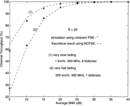
2for very slow fading. The theoretical and simulation results are plotted in Fig. 3-3 for N = 20. In the simulations, coherent PSK over a Rayleigh fading channel with additive white Gaussian noise is used for the channel model. The Rayleigh fading signal is generated with a technique described in [9, pp. 70-76], where a set of low
90 80 0 70 :3 --C £ 60, t.-c 50 40 30 on 5 10 15 20 25 30 35 40 Average SNR (dB)
Figure 3-3: Channel Throughput of a Simple ARQ Protocol
frequency oscillators are used to provide the Doppler shifts to the carrier frequency
fc
assuming uniform arrival angles. Slow and fast fading were simulated using 900 MHz carrier frequency with v = 1 km/hr at 8 kbits/sec and v = 200 km/hr at 1 kbits/sec, respectively. The theoretical curves are plotted with a 6 dB offset because NCFSK performs 6 dB worse than coherent PSK [18] at large SNR values (e.g., the plotted theoretical result at 5 dB is computed using 11 dB SNR value, 10 dB result is obtained with 16 dB, and so on). The discrepancy between the theoretical result and the simulation result at low SNR values is caused by the fact that at low SNR values, the performance difference between coherent PSK and NCFSK is less than 6 dB.
3.4
Imperfect Feedback Channel
In the study of ARQ protocols, it is usually assumed that the feedback channel is perfect. This assumption can not be justified when the feedback channel is also
/ _(1),.. 0/ A /• / / / (2)/ N=20
- simulation using coherent PSK : *
/
/ theoretical result using NCFSK:
-/
/ (1) very slow fading
I 1 km/hr, 900 MHz, 8 kbits/sec
/ (2) very fast fading
- /
/ 200 km/hr, 900 MHz, 1 kbits/sec
-II
4 t' tn
subject to Rayleigh fading. An imperfect feedback channel can cause unnecessary retransmissions and increases the number of undetected errors. The effect of an imperfect feedback channel on the channel throughput is considered in this section. For the current discussion, perfect error detection is assumed.
The analysis is carried out for the ARQ protocol in the previous section with a Rayleigh fading feedback channel. The feedback channel is assumed to be statisti-cally independent from the forward transmission channel. Again, we use (Pa(.)) to denote the probability of receiving an erroneous packet and use (P,(.)) to denote the probability of accepting an error-free packet. The quantity y can be expressed as
n = 1 + [(P (71))(P (71)) + (P (71Y))] + [(PJ(71))(P: (_'Y1)) + (Pd (71))]
[(p (2)) C(72)
+
P() (72))] + ... . (3.12)Intuitively, [(P(71i))(Pcb(71)) + (Pb(71yi)) ] represents the occurrence probability of the
first retransmission. It occurs when the acknowledgment was detected in error (e.g.,
(P{(71))) regardless of what happened on the forward transmission channel or when
the acknowledgment correctly indicated the detection of an erroneous packet (e.g.,
(Pf (71))(Pb(71yi))). The superscripts
f
and b are used to denote the forward and back channels, respectively. The subscripts in the {7,} are shown explicitly to indicate how the equation was obtained. Since the{%}
are statistically independent, the subscripts can be dropped to further simplify the equation:S= 1+ [(Pf (7))(P(7)) + (Pd(7))] + [(Pd (7))(P(7)) + (Pd(7))]2 +
[(Pd
())(P70 ()) + (P(7))]
3+...
1 1 - [ (Pfyd
+(d
Pd b))(Pcb ) 1 1 [1 - (P (y))] [1 - (Pb(7))] = f Yb (3.13)[13]. The result in (3.13) is intuitively satisfying. Since the forward transmission channel and the feedback channel are statistically independent, the expected number of transmissions needed to deliver a packet is the product of the expected number of transmissions needed to deliver a packet when the feedback channel is perfect (Wf) and the expected number of transmissions needed to deliver the acknowledgment (7b).
10Vi 90 80 60 50 40 N 20 /
very slow fading / 1 km/hr, 900 MHz, 8
/ //
//
perfect feedback channel imperfect feedback channel es
simulation:simulation: *
I: dashed
timation: solid
10 15 20 25
Average SNR (dB) 30 35 40
Figure 3-4: Channel Throughput for Imperfect Feedback Channel
We proceed to verify the analysis as follows. First, we choose a packet size N = 20 for both the data packet on the forward path and the acknowledgment packet on the feedback path. Both channels are fading at the identical rate of v = 1 km/hr,
f, = 900 MHz, and 8 kbits/sec transmission rate. We then perform software simula-tion on the ARQ protocol in the previous secsimula-tion (with a perfect feedback channel). The result is shown in Fig. 3-4 as dashed line. The square of the result is used as an estimate of the channel throughput for the same ARQ protocol when the feedback channel is changed from a perfect one to one that is subject to Rayleigh fading. This estimate is plotted as a solid line in Fig. 3-4. Finally, simulations are performed for
an
5
If•lk . . . -- W C
=A
the ARQ protocol from the previous section with a Rayleigh fading feedback channel. The results are also plotted in Fig. 3-4. The close agreement between the simulation results and the estimated results renders credence to the analysis.
3.5
Memory ARQ
In the ARQ protocol discussed above, whenever a data packet is detected in error, that packet is discarded. The receiver waits until an error-free packet is received. Er-ror detection is assumed to be perfect. The basic idea behind memory ARQ schemes is to make use of the erroneously received packet and combine them with their re-transmitted copies in decoding the re-transmitted data packets [29]-[34]. By combining an arbitrary number of noisy packets, a simple variable rate repetition code is ob-tained. The error correction capability of this code increases with decreasing code rate. The reason we introduce this concept here is that a repetition-type FEC scheme using code-combine is discussed in Chapter 6.
The scheme we implemented in software operates as follows. The first time a packet is received, the receiver operates on the received packet alone to decode the transmitted data packet. If the packet is error-free, the receiver sends a positive acknowledgment to the transmitter; otherwise, the soft decision output of the decoder
(Fr)
is saved in a receiver buffer and a negative acknowledgment is sent. If the second transmission is successfully decoded, the receiver buffer is cleared and a request for a new packet is sent; otherwise,the soft decision output of the decoder (r'F2) is combinedwith r'F. The combined packet, r'F + r2 is then decoded. If r' + r'2 is successfully
decoded, the receiver buffer is cleared; otherwise a retransmission request is sent. This procedure continues until the packet is correctly received.
The channel throughput efficiency of the ARQ protocol in Section 3.3 with code-combine decoding is presented here. The quantity y becomes:
Note that this equation is derived from (3.8) by including the code-combine failure probabilities in each successive terms. The meaning of (Pd (71, Y2, 71 + 72)) should be obvious: it is the probability that errors were detected at the initial transmission and the first retransmission as well as at the first level of code-combine decoding. The notation 71 + 7(2 in (3.14) is used to convey the fact that the failure probability at the first level of code-combine decoding is depend on the SNR values on both the first and second receptions. It should also be clear that, (Pad(1, 72, 71 + 72)) is less than (Pd(71, '72)), (Pd(7'2, 2171 •72•3 1 -1- 2 + 7"3)) is less than (Pd(Y/1,Y2,73)), and so
on. As a result, memory ARQ has a higher channel throughput than its corresponding ARQ scheme without code-combine decoding.
The evaluation of 7 is difficult due to the statistical dependencies among detected error probabilities on individually received frames and the combined frames. We only seek lower and upper bounds on r. Following Sindhu's approach in [29], a simple lower bound on r is obtained by neglecting high order terms in (3.14):
r > 1 + (Pd("1)) = I ± (P'7)) . (3.15)
An upper bound is given by r without code-combine decoding, namely 1
S<
1
(3.16)
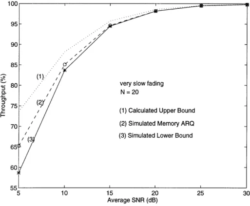
S 1 - (PW (7)) (3.16) Since the channel throughput is the inverse of r, the lower bound on channel through-put is given by the inverse of the upper bound on y; likewise, the upper bound on channel throughput is given by the inverse of the lower bound on Y. The upper per-formance bounds are plotted in Fig. 3-5 and Fig. 3-6 for the very fast and very slow fading limit, respectively. The lower performance bounds are obtained by simulations since they are the channel throughputs without code-combine decoding. Again, be-cause the bounds are computed for NCFSK and the simulations use coherent PSK, the calculated results are shown with a 6 dB offset as discussed in Section 3.3. The channel fading parameters for the slow and fast fading limits are identical to the ones given in Fig. 3-3. For the results illustrated here, the improvement in throughput
-0 CL 0-=3 5 10 15 20 25 30 Average SNR (dB)
Figure 3-5: Code-Combine Decoding on Fast Fading Channels
is not very significant. This is because code-combine decoding was not used very frequently due to the fact that a great majority of the packets were delivered with fewer than two transmissions. These figures also illustrate that at faster fading rates, time diversity benefit is much greater and the improvements in throughput efficiency due to combine decoding success is significantly higher than the slow fading case.
3.6
Concluding Remarks
This chapter has been a brief tour through several transmission protocols. The proto-cols were simple enough such that analysis were feasible. The insights gained from the discussion will be used in the following chapters to design practical data transmission protocols.
As an implementation issue, the acknowledgment frame size should be kept to the smallest practical size because of the multiplicative effect an imperfect feedback
^^n
0-:3 0--C I-5 10 15 20 25 30 Average SNR (dB)
Figure 3-6: Code-Combine Decoding on Slow Fading Channels
channel has on the channel throughput.
With memory ARQ, we showed that substantial gain in channel throughput effi-ciency is possible when erroneous data packets are used in a code-combine decoding scheme. In essence, code-combine is a simple repetition code. Its performance is greatly influenced by the correlation between the erroneous packets that are com-bined, with the probability of success being higher when they are decorrelated.
Chapter 4
Concerning JPEG Coded Still
Images
The previous chapter dealt with some fundamental aspects of error control protocols. In the next three chapters, the concepts developed there will be used and expanded in the design of practical error control schemes for the transmission of JPEG coded still images over slow fading channels. It is therefore appropriate for the current chapter to describe several relevant features of these JPEG coded still images. An understanding of the image coding structure is an essential step toward understanding the error control scheme design philosophy to be presented later.
4.1
Division of JPEG Coded Image Data
A complete description of the JPEG still image coding scheme is given in [40]. We discuss only briefly some relevant features. For the current discussion, the JPEG compressed data can be categorized by their relative importance. Typically less than 1% of the JPEG coded still image data consists of the extremely important markers. These markers contain the start and end of image information, transformation and quantization tables, and other essential information required to interpret and decode the compressed image data. We label this Type-IA information. Throughout the JPEG coded image data, with our choice of parameters for the coding options, another
set of markers occur at the end of every 16 x 16 block known as Minimum Coded Unit (MCU). These markers are very important, albeit not as important as the Type-IA markers described above. They contribute about 5-10% of the entire compressed image data. We label this Type-IB information. Both the Type-IA and Type-IB markers can be uniquely identified by a two-byte code. The first byte of the marker is a byte-aligned Oxff (hexadecimal ff) and the second byte is a code that identifies the function of the marker. Collectively, Type-IA and Type-IB markers are called Type-I information. The rest of the JPEG coded still image data contains the entropy-coded segments. We label these entropy-coded segments the Type-II information.
4.2
Effects of Transmission Errors
Transmission errors in the Type-I markers have severe consequences on the received image quality. A single bit error in the Type-IA markers may cause the entire image to be lost when the JPEG still image decoder fails to interpret the image and refuses to provide any output. When errors occur in isolated Type-IB markers, the decoder may be able to decode the image and provide an image with 16 x 16 blocks of data severely distorted corresponding to the erroneous Type-IB markers. When a Type-IB marker is accidentally converted to a Type-IA marker, the JPEG still image decoder fails with very high probability. For the Type-II information, although it is desirable to achieve the lowest BER possible, transmission errors are not as disastrous. However, the critical thing to look out for when errors occur in these entropy-coded segments is that transmission errors may convert them into Type-I markers which may crash the JPEG image decoder. Burst errors in these entropy-coded segments corrupting a long string of consecutive MCU can also severely degrade the received image quality. To illustrate these effects, we start with a JPEG coded still image (Fig. 4-1) and selectively introduce errors throughout the coded data stream. We first replace one of the Type-IA markers, Oxffd8, the start of image marker, with Oxffd9, the end of image marker. Unfortunately, the image cannot be shown because the JPEG still image decoder fails to provide any output as a result of this single bit error. In
Figure 4-1: Color Image: Original Image
Figure 4-3: Color Image: Single Bit Error Causing Type-IB to Type-IA Conversion
Fig. 4-2, one of the Type-IB markers, Oxffd2, is replaced by Oxffd3, yet another Type-IB marker. Note that this is also just a single bit error. The still image decoder fails to decode the block of 16 x 16 pixels where the single bit error occurs, and this entire block is unflatteringly shown with uniform gray scale. This can be seen approximately 1.4 inches from the right and .2 inches from the top of the image. Finally, one of the Type-IB markers is accidentally converted to a Type-IA marker (0xffd4 converted to Oxffc4, which is the marker that defines the Huffman tables); the resulting image is distorted beyond recognition (Fig. 4-3) due to this single bit error. Note that the JPEG still image decoder correctly decodes the image up to the erroneous Type-IB marker, it then gives up decoding the rest of the image beyond this marker.
4.3
Implications for Transmission Protocol
De-sign
Because of the aforementioned transmission error effects, an overall transmission pro-tocol must apply different levels of error protection for the different kind of data segments in order to fully use the scarce resource of the channel.
Obviously, the Type-IA markers require the highest level of error protection. These markers must be received error-free when possible. Although transmission errors in the Type-IB markers are not as critical as errors in the Type-IA markers, the Type-IB markers are more populous than the Type-IA markers. The majority of the JPEG coded still image data is the entropy-coded Type-II segments. Bit error rates of 10i are satisfactory for the entropy-coded Type-II segments provided that transmission errors do not give rise to unexpected markers. When a feedback chan-nel is available, ARQ protocols may be used to transmit the Type-IA and Type-IB markers. In the absence of a feedback channel, the Type-IA and Type-IB markers may be transmitted with a repetition-type FEC scheme. The Type-IA marker may be transmitted more times than the Type-IB markers to provide more protections for the Type-IA markers. Regardless of which scenario is applied, the Type-II information is transmitted only once.
The remaining chapters of this thesis are devoted to the design of practical JPEG coded still image transmission protocols on very slow fading channels. Chapter 5 is devoted to the study of an unequal error protection scheme which utilizes a novel switched transmit antenna diversity technique in combination with an ARQ protocol to transmit the Type-I information while transmitting the Type-II information in the time slots left idle by the ARQ protocol. A repetition-type FEC scheme is considered in Chapter 6. Chapter 7 treats practical laboratory implementation of error control schemes for the transmission of JPEG coded still images.
Chapter 5
Switched Transmit Antenna With
Feedback Protocol
Diversity techniques are extensively used in today's communication systems to reduce the severity of fading. This chapter builds on the foundations of the previous chapters to design a practical JPEG coded still image transmission protocol using a novel switched transmit antenna with feedback diversity technique.
Section 5.1 introduces certain aspects of the 4-DPSK modem and convolutional codes. In Section 5.2, the JPEG coded still image transmission protocol using the switched transmit antenna diversity with feedback technique is treated. Specifically, a Stop-and-Wait ARQ protocol is used to transmit the Type-I information while the Type-II information is transmitted using the time slots left idle by the ARQ protocol. Simulation results are presented to determine the effect on the average BER of the Type-II information and the ARQ system's channel throughput efficiency of the number of transmit antennas, feedback response time of the system, frame size, and channel fading rate.
5.1
4-DPSK and Convolutional Codes
In this section we summarize certain relevant features of the modulation and demod-ulation techniques to be used in the simdemod-ulation studies and implementations. The
basic concepts of convolutional coding and block interleaving are also introduced.
5.1.1
4-DPSK
In preparation for implementation, we chose 4-DPSK as our modulation scheme. A clear understanding of its operating principles is crucial when transmit antenna diversity technique is applied later in this chapter with this modulation scheme.
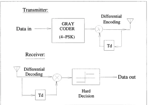
Figure 5-1: 4-DPSK Modem
Referring to Fig. 5-1, the digital data to be transmitted is pairwise mapped to a complex 4-PSK signal using Gray coding. The complex 4-PSK signal is then differ-entially encoded by multiplying it with a delayed version of the transmitted signal prior to transmission. At the receiver, demodulation is done by making a decision on the product of the received signal with a delayed version of the previously received signal [18, pp. 266-271].
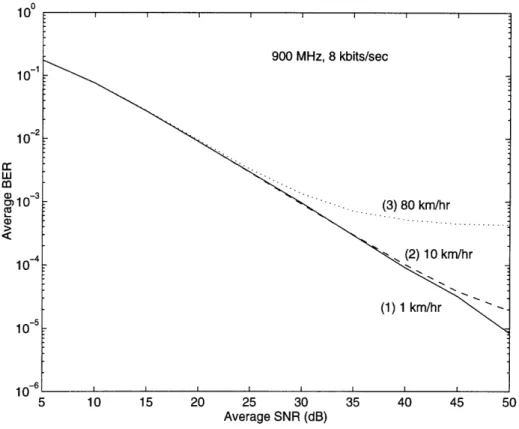
The 4-DPSK demodulator requires very small phase changes between successive data symbols for it to work reliably, hence it performs better on slow fading channels than on fast fading channels. This is verified by a theoretical result given in
[35]
andIU 10- 1 10- 2 C -3 10- 4 10- 5 1 -6 5 10 15 20 25 30 35 40 45 50 Average SNR (dB)
Figure 5-2: Average BER Performance of 4-DPSK On Rayleigh Fading Channels
the computer simulation results depicted in Fig. 5-2. The implications can be seen in the switched transmit antenna diversity scheme to be discussed later, where the transmitter switches from one antenna to another in a controlled fashion, creating abrupt phase changes on the received signal. One solution is to add two known bits to the beginning of each data packet for the demodulator to establish a phase reference once an abrupt change occurs. Bit stuffing (two bits per data packet) of the modulator and demodulator is used in the simulation studies.
5.1.2
Convolutional Coding and Block Interleaving
In practice, the data is rarely just modulated and then transmitted across the chan-nel without any form of protection against multipath fading. Convolutional codes are routinely used to improve the signal transmission performance. However, since most convolutional codes are designed for AWGN channels, interleaving is required to randomize the burst errors on fading channels for the channel code to function
900 MHz, 8 kbits/sec
... . .. . . .(3) 80 km/hr.. . . ...
(2) 10 km/hr
(1) 1 km/hr
effectively. This subsection briefly illustrates these concepts.
The convolutional encoder loads the message bits into a tapped shift register. Certain bits of the fully loaded shift register are modulo 2 added to generate the encoded data bits. Usually several bits are generated for every input bit. At the receiver, the channel decoder usually employs the Viterbi algorithm with soft decisions to decode the received data stream. An in-depth treatment of convolutional coding with Viterbi decoding is given in reference [12, pp. 358-399].
The rationale for interleaving is that it is much more difficult for a convolutional code to correct clustered errors than it is to correct the same number of errors when they are dispersed. A block interleaver writes the data to be transmitted into a m x n matrix column-wise. The transmitter reads out the bits row-wise. The deinterleaver performs the inverse operation of the interleaver. It stores the received data row-wise in a similar m x n matrix. The stored data bits are read out column-row-wise by the decoder [39, pp346]. Therefore, if a burst error of length n were received, the interleaver effectively converts the burst error into n single bit errors, which is much easier for the convolutional code to correct.
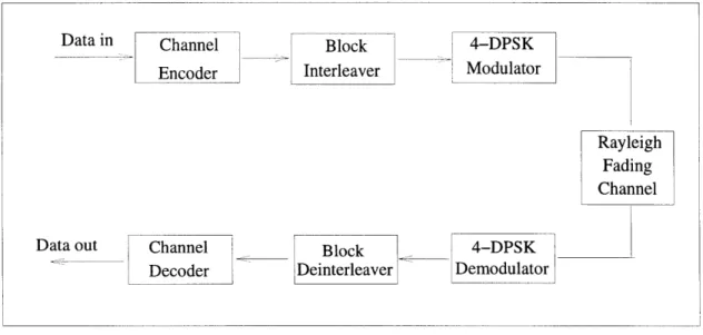
Data in Channel Block 4-DPSK
Encoder Interleaver Modulator
Rayvleigh
R~v~eirh adin
Fading
Channel
Data out Channel __ Block _ 4-DPSK
Decoder Deinterleaver Demodulator
Figure 5-3: Block Diagram of the Communication System
10-1 102 Er w (D -3 o10 10 -i n-6 5 10 15 20 25 30 35 40 Average SNR (dB)
Figure 5-4: Convolutional Coded 4-DPSK Average BER Performance
resulting communication system is depicted in Fig. 5-3. Computer simulations were performed for this communication system to determine its average BER performance at various channel fading rates and interleaver sizes for a rate 1/2, memory 2 convolu-tional code. The results are shown in Fig. 5-4. As can be seen in Fig. 5-4, the channel code performs better at faster fading rates and larger interleaver sizes because errors are less bursty under these conditions. Also illustrated is the difficulty in obtain-ing diversity benefit when the channel is very slowly time-varyobtain-ing. At v = 1 km/hr,
f, = 900 MHz, and 8 kbits/sec, with the 8 x 12 interleaver, there was virtually no coding gain; even when the interleaver size was increased to 64 x 192, the coding gain was still under 10 dB at 10-3 BER level. Note that by rearranging the data, processing delays are introduced. The delay in the 64 x 192 interleaver deinterleaver pair may be too large for some voice or data applications. We will show in Chapter 6 how to increase the correcting power of the channel code with a transmit antenna diversity technique without incurring long delays.
5.2
Switched Transmit Antenna with Feedback
Switched transmit antenna with feedback is a form of space diversity with the diver-sity branches implemented at the base station (i.e., forward channel transmitter). An excellent treatment of this technique for the case of two transmit antennas in an ana-log FM system is given in [9, pp. 399-423]. The treatment for an arbitrary number of transmit antennas used in a data transmission system with binary DPSK is consid-ered in reference [36]. In addition to the three conventional space-diversity combining methods at the receiver: selection diversity, equal gain combining, and maximal ratio combining [9, pp. 313-325], switched diversity at the transmitter represents an addi-tional diversity dimension that can be effectively exploited to achieve more reliable communication in the presence of multipath fading. The switched transmit antenna diversity scheme can be simply implemented since a feedback channel already existed in an ARQ system. We devote this section to study such schemes.
5.2.1
Principles of Operation
In a traditional switched transmit antenna with feedback scheme [9, pp. 399-423], the receiver is constantly comparing the received signal strength to a predetermined threshold. When the received signal falls below this threshold, a signal is sent to inform the transmitter to use a different transmit antenna.
In the scheme to be studied, the switch triggering mechanism is very different. To better appreciate the differences, a block diagram of the JPEG coded still image transmission protocol employing switched transmit antenna with feedback diversity is shown in Fig. 5-5. It consists of an ARQ system for transmitting the Type-I infor-mation and another system for transmitting the Type-II inforinfor-mation. The Type-II information is protected by a rate 1/2, memory 2 convolutional code with block in-terleaving. The ARQ system uses the standard CRC-16 for error detection. 4-DPSK is used to modulate and demodulate both the Type-I and Type-II information. The feedback channel is not shown. In this scheme, we do not set a signal threshold level. When a positive acknowledgment is received at the transmitter, the channel is
as-A
Type-II Data
Type-I Data
(a) Forward Channel Transmitter Retransmission Request Controls Switch
4-DPSK Block Channel
emodulator Deinterleaver Decoder
4-DPSK CRC-16 Retransmission
emodulator Decoder Request
(b) Forward Channel Receiver
Figure 5-5: Switched Transmit Antenna With Feedback Protocol
ii'
I I