Cinema 3D: large scale automultiscopic display
The MIT Faculty has made this article openly available.
Please share
how this access benefits you. Your story matters.
Citation
Efrat, Netalee et al. “Cinema 3D.” ACM Transactions on Graphics
35, 4 (July 2016): 1–12 © 2016 Association for Computing Machinery
(ACM)
As Published
http://dx.doi.org/10.1145/2897824.2925921
Publisher
Association for Computing Machinery (ACM)
Version
Author's final manuscript
Citable link
http://hdl.handle.net/1721.1/111082
Terms of Use
Creative Commons Attribution-Noncommercial-Share Alike
Cinema 3D: Large Scale Automultiscopic Display
Netalee Efrat∗1 Piotr Didyk2 Mike Foshey3 Wojciech Matusik3 Anat Levin1 1Weizmann Institute 2Saarland University, MMCI / MPI Informatik 3MIT CSAILFigure 1: The standard approach to the design of automultiscopic 3D displays attempts to cover the angular range of all viewer positions. However, there are usually unavoidable trade-offs between the angular range and resolution of such displays. Therefore, an application of automultiscopic technology to real-sized 3D cinema, where viewing range is usually very wide, would typically involve poor spatial/angular resolution (left), or a restricted range of screen distances. In contrast, we suggest a 3D display architecture that only presents a narrow range of angular images across the small set of viewing positions of a single seat, and replicates the same narrow angle content to all seats in the cinema, at all screen distances (right).
Abstract
While 3D movies are gaining popularity, viewers in a 3D cinema still need to wear cumbersome glasses in order to enjoy them. Auto-multiscopic displays provide a better alternative to the display of 3D content, as they present multiple angular images of the same scene without the need for special eyewear. However, automultiscopic displays cannot be directly implemented in a wide cinema setting due to variants of two main problems: (i) The range of angles at which the screen is observed in a large cinema is usually very wide, and there is an unavoidable tradeoff between the range of angular images supported by the display and its spatial or angular resolutions. (ii) Parallax is usually observed only when a viewer is positioned at a limited range of distances from the screen. This work proposes a new display concept, which supports automultiscopic content in a wide cinema setting. It builds on the typical structure of cinemas, such as the fixed seat positions and the fact that different rows are located on a slope at different heights. Rather than attempting to display many angular images spanning the full range of viewing angles in a wide cinema, our design only displays the narrow angular range observed within the limited width of a single seat. The same narrow range content is then replicated to all rows and seats in the cinema. To achieve this, it uses an optical construction based on two sets of parallax barriers, or lenslets, placed in front of a standard screen. This paper derives the geometry of such a display, analyzes its limitations, and demonstrates a proof-of-concept prototype. Keywords: Automultiscopic 3D displays, parallax barriers Concepts: •Hardware → Displays and imagers;
∗e-mail:[email protected]
Permission to make digital or hard copies of all or part of this work for personal or classroom use is granted without fee provided that copies are not made or distributed for profit or commercial advantage and that copies bear
1
Introduction
3D stereoscopic movies are gaining increasing popularity. The basic technology projects on the same screen two stereo images, which are filtered at the viewer’s eyes using polarized or anaglyph glasses. The shortcomings of this technology are the inconvenience of wearing special glasses, as well as the fact that the viewer only perceives depth due to binocular parallax, and not due to motion parallax. Recently there is an increased interest in bringing automultiscopic display technology into cinemas, as it eliminates the need for spe-cial glasses. The basic construction of such displays is based on the parallax barrier principle [Ives 1903] that allows encoding and projecting multiple angular images from the same screen. However, parallax barriers have two main limitations: (i) viewers have to be at a certain distance away from the screen for optimal experience, and (ii) the display has to cover a wide field of view to accommodate all viewer positions, which leads to unavoidable tradeoffs with spatial or angular resolutions. Advanced automultiscopic displays have improved on the basic parallax barrier principle, but variants of the same tradeoffs are still present.
In this work, we design an automultiscopic display that provides a 3D experience to an audience that observes a screen from a wide range of distances and angular positions, as typical in a cinema hall. We follow the observation that a viewer in a specific seat can only move his viewpoint within a tiny subset of angles limited by the seat width.
this notice and the full citation on the first page. Copyrights for components of this work owned by others than ACM must be honored. Abstracting with credit is permitted. To copy otherwise, or republish, to post on servers or to redistribute to lists, requires prior specific permission and/or a fee. Request permissions from [email protected]. c 2016 ACM.
SIGGRAPH ’16 Technical Paper,, July 24-28, 2016, Anaheim, CA, ISBN: 978-1-4503-4279-7/16/07
Figure 2: Parallax barriers and lenticular lenses. (a) Top view of a parallax barrier display, composed of 4 different angular images (color coded). A viewer at the primary viewing zone can see 3 stereo images when shifting his head horizontally. A viewer at a secondary viewing zone can see the same 3 stereo images with a pixel shift. However, if the viewer’s left and right eyes fall in different zones, transition artifacts are observed. (b) To improve light efficiency, parallax barriers can be replaced with lenslets.
Thus, it is enough for the display to support the narrow angular range within a particular seat. The same narrow angular content is replicated by our display to all seats in the cinema regardless of their viewing angle or screen distance. In contrast to recently proposed wide field of view light-field displays, such as [Hirsch et al. 2014], this approach reduces the number of angular images that has to be displayed by approximately one order of magnitude, and therefore, enables higher spatial and angular resolution over individual seats. In addition, it simplifies the process of content generation as fewer angular images have to be provided to the display. The fact that all viewers can observe the scene from the exact same angular range, and thus experience exactly the same content, is another feature desired by directors and cinematographers.
While previous screen designs exploited this observation, the key challenge of this work is making such a display work for viewers at different distances from the screen. We solve this problem by exploiting the natural structure existing in cinemas, which are de-signed such that viewers are unobstructed. This is achieved either by placing the rows at different heights on a slope, or by placing the screen above the viewers, as in drive-in theaters. As a result viewers at different rows observe the screen from different vertical angles. Using this observation we construct a structure similar to the crossed-slits camera [Zomet et al. 2003], with two layers of barriers (or lenslets) that steer the rays from each pixel to each row of viewers, achieving equal parallax at all screen distances. This paper derives the geometry of the new display and analyzes its resolution tradeoffs and aberrations through detailed simulations. We also demonstrate a small proof-of-concept prototype and the promising multiscopic images it produces.
1.1 Parallax barriers and their limitations
Parallax barriers are the simplest version of automultiscopic displays, dating back to the beginning of the 20th century, e.g., [Ives 1903; Lippmann 1908]. They enable 3D perception without the need for special eyewear. This is achieved using a regular screen displaying interleaved columns from different angular images of the scene. A parallax barrier, an array of vertical blocking slits, is placed in front of the screen. Due to the slit occlusion, one can observe different screen pixels from different viewpoints. When the viewer is located at the proper distance, every eye sees only columns belonging to one of the angular images and hence stereo perception is achieved (Fig. 2a). The light efficiency of parallax barriers can be improved if they are replaced with lenticular sheets (Fig. 2b). While for sim-plicity we consider barriers here, all observations hold for lenticular sheets as well.
Note that if the angular range of the display is wider than the
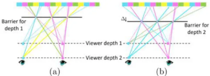
dis-Figure 3: The depth sensitivity of parallax barriers: (a) A viewer at depth 1 sees at each eye rays from the same angular image. However, this no longer holds when the viewer distance is changed, as rays from different angular images converge at the same viewpoint. (b) Changing the distance between the barrier and the screen can adjust the display to a different viewer distance, but no barrier position can accommodate all viewing distances simultaneously.
tance between the eyes, an observer can move horizontally without destroying stereo perception. Moreover, as illustrated in Fig. 2a, the main viewing zone produced by parallax barriers is essentially replicated, and an observer in secondary viewing zones can see the exact same content. However, depth reversal artifacts occur at the boundaries, when the left eye sees the rightmost angular image from one zone and the right eye the leftmost angular image of the next zone. The replicated viewing zones property makes parallax barriers attractive in a cinema setting, where viewers have fixed seats. We can make the angular range of the display as wide as the individual seats and align the transition between viewing zones with the seat boundaries, where a viewer is less likely to position his head. The main shortcoming of parallax barriers is that they work only for a fixed viewer distance. As illustrated in Fig. 3a, when the viewer distance varies, rays focusing at a single point do not all originate from the same angular image. While we can adjust the display for a new viewing distance simply by varying the distance between the barriers and the screen (Fig. 3b), a single barrier distance cannot accommodate all viewer rows. This limitation is the main motivation behind our construction, which effectively achieves different barrier distances for viewers at different rows. This is made possible due to the fact that the slanted cinema arrangement causes viewers at different rows to observe the screen from different vertical angles. In contrast to general light-field displays which produce parallax in both horizontal and vertical directions, standard automultiscopic screens provide only horizontal parallax. This is sufficient for stereo-scopic presentation as viewers usually sit in an upright position which results only in a horizontal eye separation. A potential bene-fit of providing motion parallax in vertical direction is minor as it would require viewers to move their heads in the vertical direction. Consequently, in our design, we focus exclusively on reproducing horizontal parallax.
1.2 Related work
Here we provide an overview of the most relevant designs of au-tomultiscopic display systems. For a more complete overview of state-of-the-art 3D display technologies please refer to [Urey et al. 2011; Masia et al. 2013].
Parallax barrier-based displays: Some recent approaches make changes to the standard parallax barrier design either in the barrier structure or the displayed content in order to improve the display quality. Lv et al. [2014] extend the angular resolution of a parallax barrier display by designing a non-uniform grid of slits that enables a few horizontal viewing zones, each having a high angular resolution. This solution still supports only a limited viewer distance. Some
displays extend parallax barrier-based displays to multiple viewers using eye tracking technology. The Random Hole Display [Ye et al. 2010; Nashel and Fuchs 2009], for example, populates parallax barriers with random holes, which allows viewers in known positions anywhere in front of the display to see a different subset of the display’s native pixels. Other approaches use eye tracking to improve the degree of movement and allow for multiple viewers by using dynamic parallax barriers [Yi et al. 2008; Peterka et al. 2008]. Du et al. [2014] manipulate the light field presented such that the tran-sitions between two viewing zones (Fig. 2a) would appear smooth, thus viewers can move continuously in space without experiencing transitions artifacts. Although this solution extends the supported range of screen distances in the room, it limits the suitable content.
Multi layers and time multiplexing: Another family of ap-proaches try to extend the angular range of parallax barriers by exploiting emerging display technologies such as multilayer panels, high-speed temporal modulation, and directional backlighting [Wet-zstein et al. 2012; Wet[Wet-zstein et al. 2011; Lanman et al. 2010; Ranieri et al. 2012]. They suggest that a simple parallax barrier can produce up to a rank-1 approximation of the light field, and that time multi-plexing and multiple layers can achieve a higher rank approximation that results in improved spatial resolution, increased brightness, and most importantly in our context, higher angular range. The above advantages come at the cost of non-periodic viewing zones, so the repeatable seats property exploited in this paper cannot be used; thus, the effective horizontal viewing range is smaller than with parallax barrier-based displays. In terms of viewer distance, since these displays provide an approximation to the central viewing cone of the light field, a viewer who sits at the designed viewing cone has the ability to change his distance to the screen and still perceive proper undistorted depth. This cone is extended compared to the one supported by simple parallax barriers, yet the range of distances from which the content is coherent is still limited. In our design, the supported range of screen distances is extended significantly to match a real cinema, by exploiting the fact that seat locations are fixed and known.
Large-scale 3D systems: The ideas behind parallax barriers have been applied in designs of large displays. First large-scale au-tomultiscopic projection systems were opened in Russia and France in the 1940s [Funk 2012]. These setups as well as their successors suffered from limited spatial resolution, reduced brightness, and the image quality varying as a function of the distance to the screen. More recently, Matusik and Pfister [2004] extended the ideas of lenticular sheets and proposed two multi-view screens illuminated by multiple projectors. Each of them projects a different view which is then reflected or refracted in an appropriate direction by an optical layer composed of lenticular sheets, diffuser, and retro-reflector. A conceptually similar system was proposed by Balogh [2006]. How-ever, he used as many as 96 and 128 LCD microdisplays panels to cover a wide viewing range and provide a system with high angular resolution. Takaki and Nago [2010] proposed a super multi-view display capable of producing 256 different views. Instead of multi-ple projectors, they used flat-panel displays with lenticular lenses. A final image was composed on a common diffuser by a set of projec-tion lenses placed between the diffuser and the flat panels. Similar designs include [Dodgson et al. 2000] and recent efforts in providing a 180-degree view of faces and humans [Nagano et al . 2013; Jones et al. 2015]. To reduce the number of display units time-multiplexing techniques can be applied. Bogaert et al. [2010] proposed a system consisting of one projector and a digital micromirror device that acts as a light modulator that redirects the light into different view-ing zones. A new approach to multi-view projection was recently proposed by Hirsch et al. [2014]. Their light-field projection
sys-tem consists of a light-field compressive projector placed behind a lenticular-based optical system that expands the angular range of the projected light field. All of the above solutions can be used for building large-scale 3D screens for cinemas, but they still attempt to cover a very wide range of viewing locations, at the cost of reduced spatial or angular resolutions. This is orthogonal to our approach that replicates a narrow range content to the entire audience.
The crossed-slits camera: Zomet et al. [2003] introduce the Crossed-Slits (X-Slits) projection, which uses a very similar con-cept for imaging rather than display. This approach uses a two-slit projection scheme in order to capture 3D information on the scene.
2
Display construction
2.1 Problem statement
Our goal is to design an automultiscopic display that projects mul-tiscopic content to a large audience in a cinema. To achieve this we use two crucial properties of a cinema seating arrangement: (i) Different seating rows have different heights and as a result, viewers in different rows observe the screen from different vertical angles. (ii) The seats in each row are placed in fixed known locations. The parameters of our setup are summarized and illustrated in Table 1. We assume the cinema has m rows, i = {1, ..., m}, located on a slope, and denote the y, z displacement between successive rows as ∆y, ∆z. Each row has seats of width w. The display should project k different angular images corresponding to k different viewpoints, such that a viewer shifting his head by `e= w/k will see a different angular image. We select `eto be approximately half the average pupillary distance. In this arrangement, a viewer sitting in a certain seat sees different images in each eye and binocular depth cues are observed. In addition, the viewer can move his head across the seat width and see one of k different angular images, resulting in motion-parallax based depth cues. To avoid depth reversal situations, in which the left eye sees the rightmost angular image from one zone and the right eye sees the leftmost angular image of the next zone, the transition between angular zones should align with seats boundaries. Since a viewer moving reasonably in his seat is less likely to position his head on the seat boundary, he should not be sensitive to transition artifacts.
2.2 Display geometry
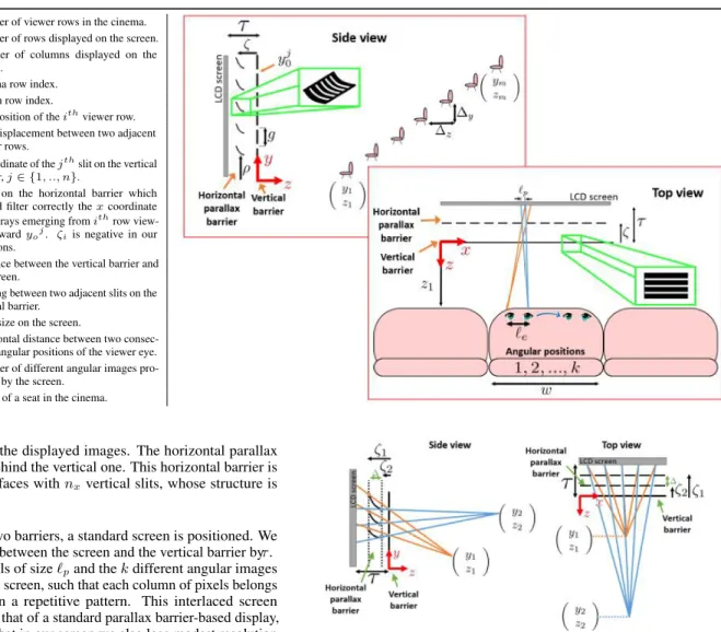
As discussed in Sec. 1.1, the main problem preventing standard parallax barriers from applying to a wide range of screen distances is that the desired distance between the barriers and the screen is different for each viewer rows (see Fig. 3). The main idea behind our simple design is that at the price of some loss in vertical resolution, we encode many automultiscopic screens in one display, one for each row. To this end, we build on the fact that, in a cinema, each row of viewers sees the screen from a different vertical angle. Therefore, we can design a barrier arrangement such that viewers in different rows see the screen through a barrier located at a different distance to the screen. Although the vertical resolution is decreased in this design, it is higher than for a standard pinhole approach (Sec. 4). In its basic configuration, our display uses two sets of barriers, which we refer to as the vertical and horizontal barriers, as they are aimed to filter rays according to their vertical and horizontal coordinates (see sketch in Table 1). To avoid confusion, note that a barrier aimed to filter a ray according to its horizontal coordinate is actually composed of vertical slits, and vice versa. A ray from the viewer to the display first intersects the vertical barrier, which is a simple plane parallel to the screen, including nyhorizontal slits, where nyis the
Table 1: Table of notations m Number of viewer rows in the cinema.
ny Number of rows displayed on the screen.
nx Number of columns displayed on the screen.
i Cinema row index.
j Screen row index.
(yi, zi) y, z position of the ithviewer row.
(∆y, ∆z) y, z displacement between two adjacent viewer rows.
yoj y coordinate of the jthslit on the vertical barrier, j ∈ {1, .., n}.
(ρi,j, ζi) Point on the horizontal barrier which should filter correctly the x coordinate of the rays emerging from ithrow
view-ers toward yoj. ζiis negative in our
notations.
τ Distance between the vertical barrier and the screen.
g Spacing between two adjacent slits on the vertical barrier.
`p Pixel size on the screen.
Horizontal distance between two consec-utive angular positions of the viewer eye.
k Number of different angular images pro-jected by the screen.
w Width of a seat in the cinema.
number of rows in the displayed images. The horizontal parallax barrier is located behind the vertical one. This horizontal barrier is a set of slanted surfaces with nxvertical slits, whose structure is derived below.
Behind the set of two barriers, a standard screen is positioned. We denote the distance between the screen and the vertical barrier byτ . The screen has pixels of size `pand the k different angular images are interlaced on the screen, such that each column of pixels belongs to another image in a repetitive pattern. This interlaced screen content is similar to that of a standard parallax barrier-based display, with the exception that in our screen we also lose modest resolution in the y axis for reasons that will be explained in Sec. 2.3.1. To account for that, we pre-blur the y axis of the angular image content. Throughout most of this paper we consider for simplicity an LCD screen, or that the interlaced screen content is displayed using back projection. In both cases we assume that the light emerging the screen is distributed in all directions, which is a desired feature for all regular screens. In Sec. 7 we discuss equivalent configurations using front projection.
The main idea behind our display geometry is demonstrated in Fig. 4. Rays from a viewer at position (yi, zi) are filtered by the vertical barrier. As a result, for each row of viewers, only rays with a certain vertical angle pass through. Since we separate the rays from different rows we can place a second horizontal barrier for each row, at the screen distance required by its z distance. This second barrier is essentially a row-dependent parallax barrier, which filters the rays from this row such that proper disparity is observed. In Fig. 4, orange rays emerging from a row at distancez1intersect the horizontal parallax barrier at distanceτ − |ζ1| from the screen, and blue rays emerging from a row at distance z2intersect the horizontal parallax barrier at a different distance τ − |ζ2| (note that ζiare negative according to our notations). Even though the rays from viewer 1 (orange rays) and viewer 2 (blue rays) reach the screen at different vertical positions, the viewers see the same content up to a small vertical shift without changing the perceived parallax. Below we derive the shape of the slanted barrier.
Figure 4: Display principle: For each viewer(yi, zi) (orange and blue),
there existsζi such that a barrier placed at that screen distance leads
to proper disparities for viewers at distancezi. Concatenating all
row-dependent barrier positionsζi, i = {1, ..., m} provides the desired shape
of the slanted horizontal parallax barrier.
2.2.1 Shaping the slanted barrier
In order to derive the shape of the slanted horizontal parallax barrier consider a viewer sitting at position (yi, zi) and looking at the screen through a vertical barrier slit at height yoj. To produce the correct parallax, we must place a horizontal parallax barrier at a distance ζi, which is a function of the row distance zi. Taking into account the y angle of rays coming from this row, we should also shift the horizontal barrier vertically above/below the vertical slit entrance yoj, by a distance we denote as ρi,j. That is, we denote the desired y, z position of the barrier as (ρi,j, ζi). Claim 1 derives a formula for (ρi,j, ζi) as a function of (yi, zi). The concatenation of all the points (ρi,j, ζi) for all viewer rows i = {1, ..., m} defines the shape of the slanted barrier.
Claim 1 Let (yi, zi) denote the location of the ithviewer row,`p the pixel size,`ethe horizontal distance between two consecutive angular positions within the seat, andτ the distance between the vertical barrier and the screen (see Table 1). Thez-coordinate of
the slanted barrierζiis a linear function ofzi, ζi= `p `p+ `e · zi+ −`eτ `p+ `e , (1)
and the y-coordinate ρi,j is a function of zi and yoj, the y-coordinate of thejth vertical slit ρi,j= yoj+ (c1· zi+ c2) · (c3· zi+ c4− yoj) zi (2) wherec1=`p+`e`p ,c2 =`p+`e−`e · τ , c3=∆y∆z,c4= y1−∆y∆zz1. A proof of this claim is provided in Supplementary Appendix A.
2.3 Display resolution
Next, we analyze the display’s vertical and horizontal resolutions.
2.3.1 Vertical resolution
To analyze the vertical resolution of our display, we denote by g the vertical distance between two adjacent slits on the vertical barrier. Since the number of image rows we can display is equal to the screen height divided by g, improved resolution is achieved when g is low. However, as illustrated in Fig. 5a and Fig. 5b, one needs to keep minimal spacing to prevent adjacent slanted horizontal barriers from blocking each other. Note that it is fine for rays from different rows to cross each other after passing through the slanted barrier, and the only implication would be a small vertical shift of the images viewed from different rows. Claim 2 derives a lower bound on g as a function of the cinema structure. It shows that resolution is a function of the difference between the angle at which the first and last viewer rows see the top row of the display. As this angular difference increases, the gap between two adjacent slits in the vertical barrier should increase, and we lose more resolution. In Sec. 3.1 we suggest how to further reduce g using additional optical elements that reduce this angular difference.
Claim 2 Denote by αithe angle of rays from theithviewer row (yi, zi) towards the top slit yony. To prevent ray blocking the slit
spacingg should satisfy g ≥ [yo ny− y 1 z1 −yo ny− y m zm ] · −ζ1z1 z1− ζ1 (3) or equivalently g ≥ (α1− αm) · −ζ1z1 z1− ζ1 (4)
A proof is provided in Supplementary Appendix B.
An important property of our construction is that all viewer rows see the screen with the same disparity shift. That is, a viewer moving his head by k`emm will see screen pixels shifted by k`pmm; this shift is identical regardless of the viewer distance. The advantage is that we do not have to adjust the screen content for different viewer rows and thus the vertical resolution does not depend explicitly on the number of rows in the cinema. However, naively adding rows to the cinema usually increases the angle difference α1− αmin Eq. (4), which does translate to resolution loss. To overcome this problem, Sec. 3.1 suggests how to improve the display resolution despite the angle difference in the target cinema.
2.3.2 Horizontal resolution
The horizontal resolution depends solely on k, the number of angular images projected by the screen. Assuming the native screen pixels are of size `p, the x spacing we achieve is k`p. Note that most existing approaches attempt to increase the viewing range directly by increasing the angular range supported by the display, which naturally increases the number of angular images k. In contrast, the angular range we need to display is rather narrow, and thus the horizontal resolution loss we suffer in practice is relatively small.
3
Optical advances
The simplified design presented above suffers from brightness and resolution problems. To increase light efficiency, we replace the barriers with lenslets, as discussed in Sec. 3.2. To improve the vertical resolution of the display, we add properly designed optical elements in front of the vertical barrier, as derived below.
3.1 Improving vertical resolution
As explained in Sec. 2.3.1, the y resolution of our display is deter-mined by g, the gap between two consecutive slits in the vertical barrier. This gap is a function of the difference between the angles α1and αmat which the first and last viewer rows see the top row of the display (see Eq. (4)). In order to improve the resolution, we place an additional optical element before the vertical barrier, to which we refer as an angle reduction element, since it is designed to reduce the angular difference between these viewing rays. To derive the shape of the angle reduction element associated with screen row j, we consider the rays rji, i = {1, ..., m} from the viewer rows towards the new element, and a new, narrower set of rays ˜rijthat connect the element to the center of the slit yoj(Fig. 5c). Each of the rays rijreaches a slightly different point on the optical element, denoted as pji. Given the correspondence between r
j iand ˜
rij, we use Snell’s law to find the normal of the optical element at the point pji. This normal is selected such that refraction at pji transfers the ray rji to ˜r
j
i. Integrating all normals provides the concave elements in Fig. 5c.
The insets of Fig. 5a and Fig. 5c demonstrate a zoomed-in part of an image obtained with and without the angle reduction elements, allowing ny= 540 compared to ny= 95 pixel rows in the cinema setting of Sec. 5. Note that in theory the angle reduction elements allow us to make the row spacing g as low as we want. However, various fabrication constraints, such as the minimal thickness of the barrier surface itself, do place some lower bound on g. In practice, in the simulations of Sec. 5 we targeted a vertical gap of g = 5mm. As a side effect, rays from a viewer row(yi, zi) passing through the angle reduction element of screen row j can spread to more than one row on the vertical barrier plane. To avoid this artifact, we add blockers between the angle reduction elements and the vertical barrier (black segments in Fig. 5c).
The angle reduction elements are constant along the x direction so that in the paraxial regime only the y component of rays bends. In practice, for viewers at the seats furthest from the center, which we will refer to as the extreme seats, the x coordinate of the viewing angle is not sufficiently small, and the element also causes modest refraction in the x direction. This causes some artifacts, as discussed in Sec. 3.4.
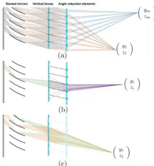
Figure 5: Optical improvements in our display.Vertical resolution: (a) In the simple barrier construction, spacing between different vertical slits is set such that rays from different viewer rows will not be blocked by a second slit as in (b). (c) Angle reduction elements can improve vertical resolution. They are optimized to refract the rays from all rows toward each vertical barrier slit, such that they span a smaller angular range. Dashed rays mark the original rays without the proposed element (wide range) while solid lines mark the rays passing through the new element (narrow range). A zoomed-in part of an image obtained with the angle reduction elements (allowingny= 540 pixel rows), can be seen as an inset, and compared to the inset in (a), a low-resolution image
without these elements (ny= 95 rows). Brightness: (d) Replacing the vertical barrier slits with lenslets can improve light efficiency. The slanted barriers are
being pushed further away from the vertical lenses to allow better focus of the rays on the slanted barriers. However, some focusing error can still be observed. Note also that rays diverge after the slanted barrier. This does not lead to additional resolution loss in practice, since the spread of the defocused rays is designed to be lower than the vertical row spacing. (e) Similarly, the slanted barriers can be replaced with slanted convex lenslets, such that rays refract through the lenslet surface. However, due to the large angle between incoming rays to the lens normal, most of the light reflects rather then refracts. To overcome this, we replace the refractive lenses with reflective mirrors (f).
3.2 Brightness
Clearly, the display barriers cause a significant light loss. Fortunately, replacing the barriers with lenslets offers a way to overcome that loss without changing the overall setup.
3.2.1 Lenslets in the vertical barrier
In order to get full light efficiency in the vertical barrier plane, we wish to focus all the rays passing through an area of size g on the vertical barrier, at the slanted barrier. However, as both the viewer rows and desired focusing distance on the slanted barrier span a range of distances, there is no simple lens that can perfectly focus rays from all viewer rows at all desired barrier positions. Thus, we attempt to find a lens that can minimize focusing aberrations. As a rule of thumb, aberrations are reduced as the distance |ζm| (Fig. 5d) between the lens and the slanted barrier increases. For larger distances, the required lens power decreases and the depth of field increases. However, increasing |ζm| results in a very thick display, as it increases the distance between the vertical lens plane and the screen. In practice, we compromise on ζm= 84cm. We use standard thin plano-convex lenses, whose only free parameter is the focal length. In order to select it, we search for the focal length that minimizes the averaged focusing aberration over all rows. Note that we only aim to bend the vertical component of the ray; thus, the lenslets have a cylindrical shape, constant along the x dimension. Another effect of the lenslets is that even though the rays that reach the slanted barrier through each lenslet are approximately focused, they diverge after passing the slanted barrier, and are defocused at their screen intersection (see Fig. 5d). However, the display
parameters are selected such that the spread is smaller than the row spacing g, so that this blur does not cause additional resolution loss.
3.2.2 Lenslets in the slanted horizontal barrier
The slanted horizontal parallax barriers can also be replaced by lenticular sheets (Fig. 5e). However, rays intersect the lenslets in a large angle relative to the lenslets’ normal due to their slanted shape and, as a result of Fresnel equations, most of the light reflects rather than refracts. To overcome this problem, we use reflective slanted mirrors rather than refractive lenses (Fig. 5f).
Deriving the structure of these mirror elements in close-form is not straightforward due to their slant, and in practice, we found the shape using nonlinear optimization. More details are provided in Supplementary Appendix D.
3.3 Overall design
The final structure of our display is illustrated in Fig. 6a. It is com-posed of 3 optical layers: angle reduction elements, vertical lenslets, and slanted horizontal mirrors. The angle reduction elements im-prove the vertical resolution as they bend the rays emerging from each row of viewers towards the vertical lenslets, into a smaller an-gular range. This allows us to use a smaller vertical spacing g. The vertical lenslets are cylindrical lenslets designed to refract the verti-cal component of the rays toward the slanted mirrors. Finally, the slanted mirrors replace the slanted barrier. Like the original barriers, they provide rays from each viewer row with the right disparity, so that the proper angular image interleaved on the screen is observed, but unlike the barriers, they do not block light.
Figure 6: (a) Our final design composed of 3 layers of optical elements: (i) angle reduction elements, (ii) vertical lenslets, and (iii) horizontal slanted mirrors. (b) Some rays from the viewer eye are blocked between the angle reduction elements and the vertical lens. (c) Despite the blockers, the angle reduction elements do not result in light loss. In the figure, green cones illustrate ray directions when no angle reduction elements are present. The exact same cone, illustrated in orange, traverses the angle reduction elements without being cropped. The main effect of these elements is to focus the cone into a narrower one, without blocking light. Note that the figure is simplified for illustration – when no angle reduction elements are present, the shape of other components in the display (slanted barriers and vertical lenses) is somewhat different.
Note that different viewer rows see the same pixel rows on the screen, e.g. the orange and blue rays in Fig. 6a intersect the screen in overlapping areas. This does not pose a problem since the content displayed on the screen is identical for all viewer rows. Fig. 6b illustrates how some rays from the viewer eyes are blocked between the angle reduction elements and the vertical barrier; however, the row spacing g is selected to be lower than the minimal unit people can resolve from the closest cinema row, so these dark regions are unobserved. As illustrated in Fig. 6c, we emphasize that the angle reduction elements do not result in any light loss compared to a design without these elements. The exact same cone of rays emerging from a screen point to a viewer eye in a setup without the angle reduction elements (green cones in Fig. 6c), reaches the viewer eye when the angle reduction elements are included (orange cones in Fig. 6c). The effect of the elements is only to focus these rays into a narrower cone, causing no light loss.
3.4 Aberration factors
As our final display is composed of several layers of optical elements, it also suffers from aberrations contributed by each of the layers. The main types of aberrations are summarized below.
Shift from the intended angular image: The angle reduction elements are intended to only refract the vertical component of the rays. This is true for small intersection angles when the paraxial ap-proximation (sin θ ≈ θ) applies. However, when the viewing angles are not sufficiently small, the angle reduction elements slightly bend the x component of the rays rather than only their y component. As a result, in large viewing angles rays intersect the slanted mirrors at
a wrong depth, leading to a horizontal shift in the intersection of the rays with the screen. This means that the viewer sees nearby views instead of the intended view (see Fig. 7a). A similar phenomenon is caused by the lenslets in the vertical barrier.
As we analyze in Sec. 5, the problem can be significantly minimized in practice by properly designing the cinema structure. The goal is to select seat positions in the cinema such that the maximal horizontal angle at which viewers see the screen will be limited. This can be achieved by placing the seats somewhat further from the screen and using a narrower spread of seats (eliminating some of the side seats) in the first rows.
Figure 7: Aberration factors. (a) Aberrations resulting from the angle reduction elements: The red fan of rays represents the desired path according to the paraxial model. However, the green fan illustrates the actual rays traveling through the system when thex component of the rays deviates from the paraxial regime. The green rays intersect the slanted barrier at a wrong depth, and as a result their intersection with the screen is shifted from the position of the intended angular image. For illustration simplicity, the figure uses slits rather than lenslets and mirrors. (b) Blur by the slanted concave mirrors: In this exaggerated illustration, rays in the middle of the display, which have a smallx component, focus perfectly on the screen. However, as thex component of the viewing angle increases, the mirrors fail to focus the light at the right distance.
Angular blur: Another type of aberration is observed when rays reaching a viewer eye arrive from a mixture of screen pixels that display different angular images. In our setup, there are two sources of misfocus: (i) the vertical lenses, and (ii) the slanted concave mirrors. As illustrated in Fig. 5d, the vertical lenses can somewhat misfocus the light on the slanted mirrors. Therefore, not all light rays intersect the slanted mirror at the intended distance. Light rays filtered at the wrong depth effectively achieve the disparity of a different viewer row and the viewer sees a mixture of nearby pixels belonging to different angular images. On the horizontal axis, the slanted concave mirrors misfocus the light on the screen at viewing angles whose x component is large, which also leads to a mixture of nearby angular images (Fig. 7b). As mentioned, we can minimize blur problems with a proper design of the seating layout.
4
Comparisons with simpler solutions
It is important to compare our design with two simpler schemes for displaying 3D content. The first solution is the simple lenticular sheet display discussed in Sec. 1.1.
A second, more sophisticated solution, is to use a pinhole array rather than two sets of slits. In this arrangement, rays from all rows are filtered by a single pinhole at a fixed distance from the screen, so different rows view the screen with a different disparity shift. However, since different rows are located at different heights, they still view the screen at different angles. Therefore, we can display different content on the screen to match the row-dependent disparity shift, as illustrated in Fig. 10. The fact that the pinhole
Figure 8: Simulating stereo images from our display, comparing the central vs. leftmost seat in two rows. Images from the extreme seats are somewhat blurrier as discussed in Sec. 3.4. Throughout this paper, theglasses icon denotes content that should be viewed with anaglyph glasses.
Figure 9: Simulating different display configurations. A simple lenticular sheet display (second column) produces good-quality images for viewers at the target distance (first viewer row). However, at a different distance (e.g. the fifth row), pronounced artifacts are observed. Our solution with barriers and only the angle reduction elements (third column) suffers from less aberration and hence provides improved resolution; however, the viewed images are very dark (brightness normalized in the figure). Our solution without angle reduction elements (fourth column) produce a lower resolution ( ny= 95 compared to
ny= 540). The naive pinholes solution of Fig. 10 (last column) gives even lower vertical (ny= 40) as well as horizontal resolutions (nx= 556 compared to
nx= 960 in our design).
Figure 10: A naive automultiscopic display, composed of a pinhole array and a screen where each viewer row sees different pixel rows on the screen. To enable coherent content, one needs to use different horizontal scaling on the angular images intended for viewers in different rows. Thus, resolution tradeoffs here are worse compared to our design.
construction requires different content for different viewer rows is its main disadvantage. As we need to allocate a separate row of screen pixels for every row of viewers, a significant resolution loss results. This problem is avoided by our construction, in which the screen content is identical for all rows of viewers, so that the same pixel rows on the screen can be shared by multiple rows of viewers (see Fig. 6a). The vertical and horizontal resolution losses are analyzed in Supplementary Appendix C, and visualized in Sec. 5.
5
Synthetic results
In this section we use ray-tracing simulations to demonstrate views from our display as well as some of the simpler alternatives. While our simulations account for the optical aberrations discussed in Sec. 3.4, we found that the effect of chromatic aberrations is negligi-ble. Therefore, we omitted them from the simulations.
We consider a cinema hall consisting of 10 rows with 7 seats in each row. The cinema is structured such that the seat width is w = 58cm, the distance between two consecutive rows is ∆z = 70cm, the height difference is ∆y = 25cm, and the first row is located z1= 7.8m away from the first layer of the display. The screen size is 2.7 × 4.3m, with pixels of size `p = 0.5mm. We use k = 9 angular images, but space the angular positions `e = w/(2k) = 3.2cm apart over seat width, where `eis the horizontal shift of eye position at which a viewer sees a different angular image. Setting `e = w/(2k) allows for better angular resolution at the price of allowing viewers to move only over half of the seat width. The screen vertical spacing is set to g = 5mm. Overall, this allows displaying images of size ny = 540 and nx = 960 pixels. The thickness of the display, i.e. the distance between the angle reduction element layer and the back screen, is 2m.
Figure 11:Angular images as perceived from different viewing positions. Each input angular image is coded by a different color. An aberration-free image should have a uniform color, but this is not fully achieved due to optical imperfections of the system. Below each image, we show transition maps visualizing in white the depth reversal artifacts . The top row demonstrates the images for the central and the extreme side seats in the first row of the cinema as seen by a viewer. There are less artifacts at the center of the viewing zone (e.g. angular position 5) relative to its boundary (e.g. angular position 8). The bottom row depicts the sensitivity of the display to variation in the viewer height, which is negligible for± 15cm deviations.
Toughout this section we use a small glasses icon at the corner of figures that should be viewed with anaglyph glasses. Figure 8 demonstrates simulated images for several seats in the cinema. Ad-ditional higher-resolution results are included in the supplementary file both in video and in JPS formats.Note that for the extreme seats, whose horizontal viewing angle is a bit large, one can see the images start to get blurrier, as discussed in Sec. 3.4.
Figure 9 compares a few display configurations for seats in two different rows. The first column represents our final display. In contrast, the second column shows results for a simple lenticular sheet display designed for the first row of viewers. The images obtained at this row are indeed good, but at other row distances, visible artifacts appear. The third column demonstrates the output of our display when only angle reduction elements are present, but the horizontal and vertical lenticular elements are replaced with barriers. Since lens aberrations are avoided, the image is somewhat sharper than the one obtained with the final display (first column). However, the barriers lead to a significant light loss (in Fig. 9, brightness has been normalized). The fourth column demonstrates our display without any optical elements, including the angle reduction elements, demonstrating a significant loss in vertical resolution. The last column simulates the naive pinhole solution. In this case both the vertical and horizontal resolutions are even lower than those of the fourth column.
5.1 Evaluation
As mentioned in Sec. 3.4, due to aberrations, the images viewed by the audience are effectively a mixture of some nearby angular images rather than only the intended one. Our goal is to evaluate the visual artifacts caused by these aberrations. We note that if in the image we see transitions between angular image j and angular image j + 1, no significant visual artifacts are observed since overall the nearby angular images vary continuously. On the other hand, we do need
to penalize discontinuous transitions between angular image k and angular image 1. Our proposed score counts the number of transition edges between image regions mapped to angular image k (red in Fig. 11) and regions mapped to angular image 1 (green in Fig. 11). We penalize such transitions as a function of their distance from the center of the image, since viewers are usually more sensitive to artifacts in the center rather than in the periphery of the screen. The Transitions Grade (TG) measure can be written as:
T G(y, z, x, v) = P r∈L wr1{r ∈ Ltransitions} P r∈L wr · 100%, (5)
where r denotes a ray hitting the screen, L the set of all such rays, Ltransitionsscreen regions where discontinuous transitions of an-gular images are present, and wrthe weight of a pixel relative to the center of the screen. This measure is a function of a specific seat in the cinema (y, z, x) and angular position (v); thus we calculate it for each of the k angular positions within each seat.
To get a sense of the angular mixture obtained in practice, Fig. 11 uses colors to encode different angular images and demonstrate the angular image from which each pixel originates. Below each image we show a map of rays falling in the transition area. In the figure color coding, these are the transitions between green and red pixels. The transition grade is essentially a weighted average of these maps. The bottom part of Fig. 11 shows the sensitivity of our display to the viewer’s height. We found that the perceived quality degradation is not significant with up to ±15cm height difference. Moreover, from a system design perspective, this can also be addressed by other means, e.g. adjustable seats.
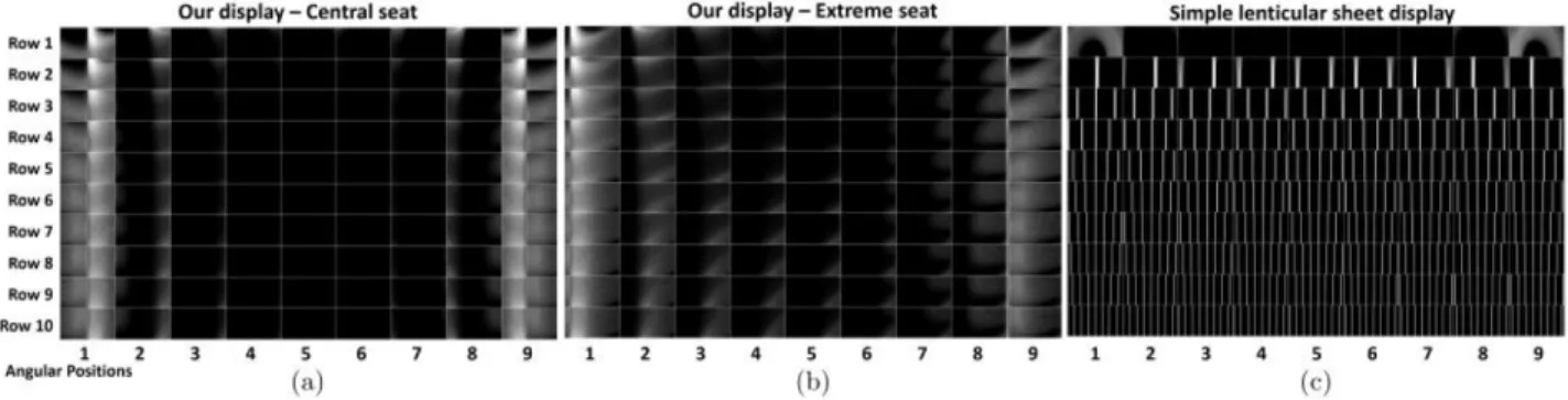
Figures 12a,b show the transitions maps for the leftmost and central seats in each row for all angular positions within that seat. First, it can be seen that the boundary angular positions (1 and k) have a bad quality and the artifacts are reduced in the middle of the angular viewing zone. For this reason we chose the number of angular images k = 9 to be large enough to allow each viewer sufficient space for free head motion before hitting the boundary artifacts. A second observation is that viewers located in the central seats (Fig. 12a) experience the best quality, but even viewers at the extreme leftmost/rightmost seats (Fig. 12b) have a sufficient set of good-quality angular positions. Fig. 12c emphasizes the degraded quality of the simple lenticular sheet display. Artifacts increase as the viewer moves further from the distance at which the display was designed. Table 2 in Supplementary Appendix E provides the numerical values of the TG score, reinforcing the above observations.
The cinema arrangement described in the beginning of this section was selected to minimize aberrations. To demonstrate the importance of a proper cinema design, we considered a second more naive cinema arrangement, with two main differences: (i) The distance between the first row and the screen is reduced from 7.8m to 5.4m, implying that the horizontal viewing angles at which the screen is observed can be larger, leading to more aberrations as discussed in Sec. 3.4. (ii) The thickness of the screen is reduced from 2m to 1.5m. The implication is that we have to use vertical lenslets with a shorter focal length, resulting in more focusing aberrations. In both cinema configurations, we designed all display elements to achieve the least possible aberrations given the cinema structure. Figure 13 compares three angular images obtained at one of the seats, for both cinema configurations. In both cases, the extreme angular images involve ghosting artifacts, but in the simpler cinema setting, there is more ghosting in the central images of the viewing zone.
Figure 12:Transition maps of images viewed from our display, from the central seat (a) and the leftmost seat (b), in all cinema rows, relative to transition maps viewed from a simple lenticular sheet display, from a central seat (c). The maps are similar at the extreme seats. In the first row the viewed images are free of artifacts (besides the extreme angular positions 1 and k); however, when a viewer changes his distance, strong transition artifacts appear.
Figure 13:Images perceived at the three leftmost angular positions of the central seat in the first row, for two different cinema configurations. In both cases the extreme angular positions involve more ghosting than the central ones, but when the cinema arrangement is properly designed (2nd row), one can reduce ghosting aberrations in the center of the viewing zone. For better visualization, the bottom row compares enlarged windows from both configurations. The transition map of each viewing position is presented at the top-left corner.
5.2 Fabrication sensitivities
In the next section we demonstrate a simple barriers only prototype. In addition, we use simulations to examine the complexities of our full design (Fig. 5f) as well as the sensitivities to some fabrication artifacts. Our simulations show that the display works as predicted even with moderate misalignment of different components. For good results we expect that the tolerance should be below a pixel size, and indeed, our simulations showed that 0.1mm misalignment between the vertical lenses and the slanted mirrors, which is 20% of the pixel size, is acceptable and does not lead to significant quality reduction. Other inaccuracies include manufacturing imperfections in the angle reduction elements and mirrors. Although not quantified, such inaccuracies would result in more aberrations, such as shift from the intended angular image and angular blur .
6
Prototype fabrication
As a proof of concept, we have fabricated a small low-resolution prototype of our display. This prototype is composed of barriers
only: the vertical barrier and the slanted horizontal parallax barrier, without lenslets or angle reduction elements. The prototype has been fabricated from aluminium sheets, cut and bent to the desired shape. It supports a rather small 10 × 20 pixel image. Since we do not use any optical elements, the resolution of our prototype is low and the spacing between pixel rows is set to 2.4cm. The overall prototype size is 35 × 28 × 28cm and it is placed in front of a standard LCD monitor that serves as the screen. Figure 16 shows the prototype and the auditorium in which it has been captured. The first row of seats is located 6m from the screen. The distance between two consecutive rows is ∆y = 1m, and their height difference is ∆z = 15cm. The first row of viewers is located 20cm below the screen.
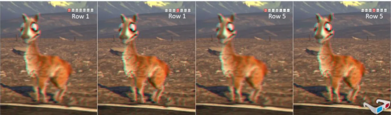
Figure 15 presents two types of test images demonstrating the good angular resolution achieved by the prototype. In the first case, each angular image has a different uniform color. In the second case, we use non-overlapping numbers to better analyze the ghosting. We capture the display from several seats spread over multiple rows in the auditorium. To test the effect of the x-viewing angle, we demonstrate views from both central seats and extreme seats. The captured images reproduce the target rather accurately. This is a
Figure 14: Two test scenes captured through our prototype. The top one illustrates 10 angular shifts of a square floating in front of a flat background, and the second one a few rotated views of pixelated figures. Top row: target angular images. Rows 2-5: angular images captured from different seats, illustrating accurate reproduction of the target. Enlarged animated illustration of the captured images can be seen in the supplementary file. Left: The interlaced angular images as displayed on the back screen. Right: the tested seat marked on the auditorium layout.
Figure 15: Two test scenes illustrating the angular resolution of the display. Top row: 10 target patterns used as angular images. Rows 2-5: the patterns captured from different rows and seats, illustrating accurate reproduction of the target. Left: The interlaced angular images as displayed on the back screen. Right: the seat at which this row of angular images was captured, marked over the auditorium layout.
Figure 16: Our prototype and capture setup. (a) The auditorium in which images were captured. A camera was placed on a rod and was moved horizontally to simulate the movement of a viewer’s head. (b) Capturing was performed at several seats in the auditorium. (c) The barriers assembly and the LCD screen behind it. (d) Emphasizing the vertical barrier (yellow) and the horizontal slanted barrier (red).
positive result with respect to related approaches [Lanman et al. 2010; Wetzstein et al. 2011; Wetzstein et al. 2012], which usually produce low angular resolution approximations to a target light field.
Figure 17:Our display can be used with a passive reflective diffused screen if we replace a single seat in a row with a multi-view projector. The projected multi-view content propagates to the passive screen via the display barriers. Due to the diffused nature of the screen, it spreads back toward all other seats in the row.
Actual 3D content that can be displayed in 10 × 20 pixel images is rather limited, yet Fig. 14 shows two test scenes: one illustrating a square floating in front of a flat background, and another showing a few rotated views of pixelated figures. We demonstrate images captured from multiple seats in the auditorium. More results as well as all design details are included in the supplementary material. Our prototype is able to project the multiscopic content to many seats at a wide angular range and in a wide range of screen distances.
7
Extensions to other screen designs
Our simulations assume the screen is an LCD display placed beyond the barriers. However, similar results can be achieved with passive screens. One option is to use back projection, i.e. project the inter-laced angular images from behind the screen. Another option is to use front projection, i.e. using a passive diffused reflective screen and a proper light field projector located in the audience area. This projector will send the angular images through our system’s optical elements. To see this, consider first a single row of viewers and replace one of the seats in this row with a 3D multi-view projec-tor, which displays multiple angular images that vary along the x dimension. As illustrated in Fig. 17, since the screen is diffused it is enough that one ray with the desired color will reach every screen point, and this color would be reflected, spreading into all other directions. To generalize this to all rows, we need to project a 4D lightfield that varies along the y axis as well.
8
Discussion
We present a new design of an automultiscopic display optimized for 3D cinemas. We exploit existing characteristics of cinemas – the fact that seat rows are located on a slope and seat locations are fixed and known. This allows the design of a simple display supporting a large audience sitting at a wide range of viewing angles and screen distances. We follow the observation that spanning the complete range of viewing angles in the entire hall is redundant, since no individual viewer moves across such a wide range. Therefore, it is enough to cover the limited angular range of one seat and replicate the same narrow-range content to all seats in the cinema. Combining this with accounting for audience layout allowed us to design an automultiscopic display that provides good image quality to viewers located at different distances. The paper derives the basic geometry of such a display and discusses how to improve its brightness and resolution using properly designed optics. We also present a simple prototype demonstrating the feasibility of the design.
Acknowledgements
The authors would like to thank the anonymous reviewers for their helpful comments and suggestions. Funding was provided by the ISF and ERC.
References
BALOGH, T. 2006. The holovizio system. In Electronic Imaging 2006, International Society for Optics and Photonics, 60550U– 60550U.
BOGAERT, L., MEURET, Y., ROELANDT, S., AVCI, A., DESMET, H., AND THIENPONT, H. 2010. Single projector multiview displays: directional illumination compared to beam steering. In IS&T/SPIE Electronic Imaging, International Society for Optics and Photonics, 75241R–75241R.
DODGSON, N., MOORE, J., LANG, S., MARTIN, G., AND
CANEPA, P. 2000. A time-sequential multi-projector autostereo-scopic display. Journal of the Society for Information Display 8, 2, 169–176.
DU, S.-P., DIDYK, P., DURAND, F., HU, S.-M.,ANDMATUSIK, W. 2014. Improving visual quality of view transitions in automul-tiscopic displays. ACM Transactions on Graphics (Proceedings SIGGRAPH Asia 2014, Shenzhen, China) 33, 6.
FUNK, W. 2012. History of autostereoscopic cinema. Proc. SPIE 8288, 82880R–82880R–25.
HIRSCH, M., WETZSTEIN, G.,ANDRASKAR, R. 2014. A com-pressive light field projection system. ACM Trans. Graph. 33 , 4 (July), 58:1–58:12.
IVES, F., 1903. Parallax stereogram and process of making same., Apr. 14. US Patent 725,567.
JONES, A., UNGER, J., NAGANO, K., BUSCH, J., YU, X., PENG, H.-Y., ALEXANDER, O., BOLAS, M.,ANDDEBEVEC, P. 2015. An automultiscopic projector array for interactive digital humans. In ACM SIGGRAPH 2015 Emerging Technologies, SIGGRAPH ’15.
LANMAN, D., HIRSCH, M., KIM, Y.,ANDRASKAR, R. 2010. Content-adaptive parallax barriers: optimizing dual-layer 3d dis-plays using low-rank light field factorization. ACM Trans. Graph. 29, 6, 163:1–163:10.
LIPPMANN, G. 1908. ´Epreuves r´eversibles donnant la sensation du relief. J. Phys. Theor. Appl. 7, 1, 821–825.
LV, G.-J., WANG, Q.-H., ZHAO, W.-X., ANDWANG, J. 2014. 3d display based on parallax barrier with multiview zones. Appl. Opt. 53, 7 (Mar), 1339–1342.
MASIA, B., WETZSTEIN, G., DIDYK, P.,ANDGUTIERREZ, D. 2013. A survey on computational displays: Pushing the bound-aries of optics, computation, and perception. Computers & Graph-ics 37, 8, 1012–1038.
MATUSIK, W.,ANDPFISTER, H. 2004. 3d tv: a scalable system for real-time acquisition, transmission, and autostereoscopic display of dynamic scenes. In ACM Transactions on Graphics (TOG), vol. 23, ACM, 814–824.
NAGANO, K., JONES, A., LIU, J., BUSCH, J., YU, X., BOLAS, M., ANDDEBEVEC, P. 2013. An autostereoscopic projector array optimized for 3d facial display. In ACM SIGGRAPH 2013 Emerging Technologies, SIGGRAPH ’13.
NASHEL, A.,ANDFUCHS, H. 2009. Random hole display: A non-uniform barrier autostereoscopic display. In 3DTV Conference: The True Vision - Capture, Transmission and Display of 3D Video, 2009, 1–4.
PETERKA, T., KOOIMA, R. L., SANDIN, D. J., JOHNSON, A., LEIGH, J., DEFANTI, T.,ET AL. 2008. Advances in the dynallax solid-state dynamic parallax barrier autostereoscopic visualiza-tion display system. Visualizavisualiza-tion and Computer Graphics, IEEE Transactions on 14, 3, 487–499.
RANIERI, N., HEINZLE, S., SMITHWICK, Q., REETZ, D., SMOOT, L. S., MATUSIK, W.,ANDGROSS, M. 2012. Multi-layered automultiscopic displays. Computer Graphics Forum 31, 7pt2, 2135–2143.
TAKAKI, Y.,ANDNAGO, N. 2010. Multi-projection of lenticular displays to construct a 256-view super multi-view display. Optics express 18, 9, 8824–8835.
UREY, H., CHELLAPPAN, K. V., ERDEN, E., AND SURMAN, P. 2011. State of the art in stereoscopic and autostereoscopic displays. Proceedings of the IEEE 99, 4, 540–555.
WETZSTEIN, G., LANMAN, D., HEIDRICH, W.,ANDRASKAR, R. 2011. Layered 3D: Tomographic image synthesis for attenuation-based light field and high dynamic range displays. ACM Trans. Graph. 30, 4.
WETZSTEIN, G., LANMAN, D., HIRSCH, M.,ANDRASKAR, R. 2012. Tensor Displays: Compressive Light Field Synthesis using Multilayer Displays with Directional Backlighting. ACM Trans. Graph. (Proc. SIGGRAPH) 31, 4, 1–11.
YE, G., STATE, A.,ANDFUCHS, H. 2010. A practical multi-viewer tabletop autostereoscopic display. In Mixed and Augmented Real-ity (ISMAR), 2010 9th IEEE International Symposium on, IEEE, 147–156.
YI, S.-Y., CHAE, H.-B.,ANDLEE, S.-H. 2008. Moving parallax barrier design for eye-tracking autostereoscopic displays. In 3DTV Conference: The True Vision-Capture, Transmission and Display of 3D Video, 2008, IEEE, 165–168.
ZOMET, A., FELDMAN, D., PELEG, S.,AND WEINSHALL, D. 2003. Mosaicing new views: The crossed-slits projection. IEEE Trans. Pattern Anal. Mach. Intell. 25, 6 (June), 741–754.