Developement of an Encapsulation Process for use in a
Universal Automated Fixturing System
by
Elmer C. Lee
B.S., Mechanical Engineering
Massachusetts Institute of Technology(1996)
Submitted to the Department of Mechanical Engineering in partial fulfillment of the requirements for the degree of MASTERS OF SCIENCE in MECHANICAL ENGINEERING
at the
MASSACHUSETTS INSTITUTE OF TECHNOLOGY JUNE 1999
@ Copyright, 1999, Masspohftsytts Institute of Technology. All rights reserved.
. ... Department of Mechanical Engineering
May 24, 1999
Certified by
Accepted by
... .. .. (I... Sanjay E. Sarma Assistant Professor of Mechanical Engineering Thesis Supervisor
...4, ..,. ... . . ... Ain A. Sonin
Chairman, Department Committee on Graduate Students
MASSACHUSETTS INSTITUTE
OF TECHNOLOGY
I IRRARIES
ENG
Development of an Encapsulation Process for use in a
Universal Automated Fixturing System
by Elmer C. Lee
Submitted to the Department of Mechanical Engineering on May 24, 1999 in partial fulfillment of the requirements for the degree of
MASTERS OF SCIENCE in MECHANICAL ENGINEERING
ABSTRACT
The perfect fixturing system would immobilize the work piece so as to allow one to cut as aggressively as the machine tool would allow. It would never obstruct the cutting path or the cutting tool. It would locate the workpiece with absolute accuracy. It would support the work piece entirely. It would easily allow for complete automation of its functions. With such a system, the line that divides rapid prototyping and mass production could be erased and manufacturing one piece would be as cost and time efficient as manufacturing ten thousand.
The development of a universal automated fixturing system is a step towards creating such a perfect fixturing system and is expected to have a profound effect on machining. Such a fixturing system will allow the decoupling of design from manufacturing, and essentially bring product design and development one step closer to true concurrent engineering. Universal Automated fixturing can also transform a machine tool into a rapid prototyping machine with many advantages over current rapid prototyping methods. The entire design process can be sped up, allowing companies to be more responsive to market changes.
Research aimed towards creating a universal automated fixturing system is discussed in this dissertation. We focus on developing an entirely new manufacturing process, which we call encapsulation molding, essential for making automate universal fixturing possible. Furthermore, we describe the hurdles of implementing such a system and the science which has been applied to better understand the process. Lastly, this dissertation contains a proposal for further work that must be pursued to truly create a universal automate fixturing system.
Thesis Supervisor: Sanjay Sarma
Table of Contents
Chapter 1: Introduction ... 6
1.1 Fixturing and Its Role in Design and M anufacturing ... 6
1.2 Past Fixturing Technology ... 7
1.3 Current State of the Art... 9
1.4 Universal Automated Fixturing ... 13
1.5 Motivation Behind Developing a Universal Automated Fixturing ... 16
Chapter 2: The Encapsulation Process and its Application Towards Fixturing ... 19
2.1 Basic Process Steps of Encapsulation... 19
2.2 W ork at Berkeley ... 22
2.3 Encapsulation in Industry ... 26
2.4 M aterial Selection ... 27
2.5 Advantages of Encapsulation Over other Fixturing M ethods ... 33
Chapter 3: Design Process of an Encapsulation System for Fixturing Applications ... 39
3.1 Primary Functional Requirements ... 39
3.2 Expanding into Sub-Functional Requirements ... 41
3.3 Decoupling into Three Separate M achines ... 45
3.4 Developing Molds for Encapsulation-Decoupling into Three Machining Strategies 46 3.5 Key Design Considerations ... 49
Chapter 4: Elements of the Automated Encapsulation System for Fixturing ... 55
4.1 M elting and Storage System ... 55
4.2 Injection M achine and Delivery System ... 57
4.3 Clamping System ... 60
4.4 M olds ...---... 68
4.5 Portable Encapsulation M achine ... 73
Chapter 5: W ork In Progress ... 79
5.1 Fixturing System ... 79
5.2 Ultrasonic Soldering ... 82
5.3 Re-M olding and W eldline Experiments ... 89
5.4 M elter Device ... 90
5.5 Automatic G-code Parser and Queue scheduler Programming ... 93
5.6 Conclusion ... 97
Bibliography ...---... 98
Table of Figures
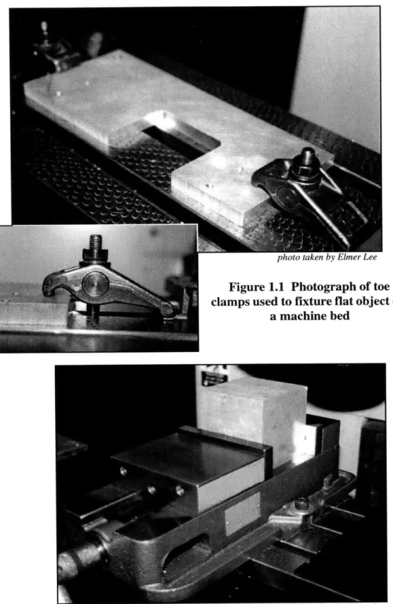
Figure 1.1 Photograph of toe clamps used to fixture flat object on a machine bed ... 8
F igure 1.2 ... - -.... .. ---... . . ... Photograph of a 2-walled vise clamp, used mainly for the workholding of rectangular, fairly stout parts ... 8
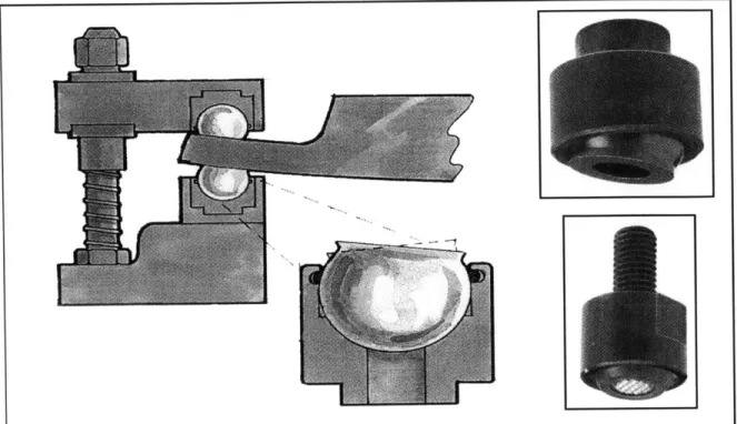
Figure 1.3 Illustrations of self-aligning ball pads for workholding of rounded plates ... 10
Figure 1.4 Photograph of precision ground expansion pins. ... 11
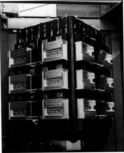
Figure 1.5 Photograph of a tombstone fixture setup ... 12
Figure 1.6 Photograph of a cluster of two walled vises ... 12
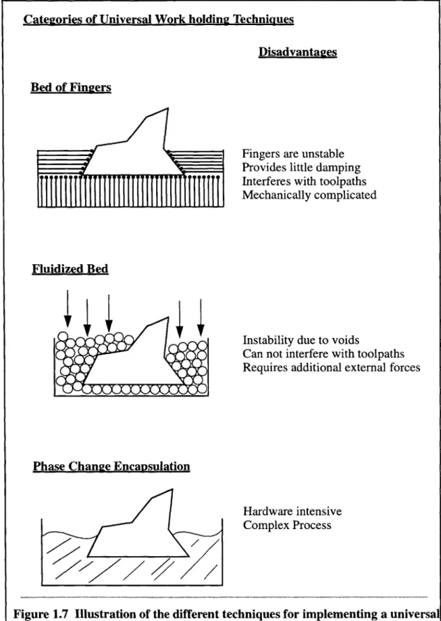
Figure 1.7 Illustration of the different techniques for implementing a universal fixturing system ... 14
Figure 1.8 Illustration of the general model of the envisioned rapid prototyping center: ... 17
Figure 2.1 Encapsulation process steps ... 21
Figure 2.2 Illustration of the thermal drift effect during remolding ... 23
Figure 2.3 Illustration of shrinkage effects on molded walls ... 24
Figure 2.4 Illustration of Cage RFPE ... 25
Figure 2.5 Encapsulating turbine blade for machining processes allows a less complex fixturing system to accommodate odd geometries. ... 27
Figure 2.6 Illustration of voids that are often formed by trapped air bubbles or shrinkage of the encapsulator ... 31
Figure 2.7 Photograph of sample parts machined using encapsulation fixturing: ... 35
Figure 2.8 Illustration showing toolpaths for machining special elements with the aid of encapsulation fixturing ... 36
Figure 2.9 Illustration of encapsulation fixture's ability to transform 2 different parts into one generic norm: ... 38
Figure 3.1 Illustration of the three fundamental machining strategies: 3-D, 2 1/2 D, AND 2-D 48 Figure 4.1 Picture of the melting/storage tank. ... 56
Figure 4.2 Cut away view shows the injection piston, including piston pump, heater, o-rings, valving, pneumatic piston and support structure. ... 58
Figure 4.3 Illustration of the flow pattern in the injection system ... 59
Figure 4.4 Illustration of the pneumatic clamping system ... 61
Table of Figures
Figure 4.5 Picture of the sliding element linear and rotary bearings provided
by L ubo Industries ... ---... 62
Figure 4.6 Top view of the head piece unit ... 64
Figure 4.7 Bottom view of the head piece unit ... 64
Figure 4.8 Illustration of the valve within the head piece ... 65
Figure 4.9 Illustration of the mold receiving area of the clamping system ... 66
Figure 4.10 Illustrations of the importance of machine orientation ... 67
Figure 4.11 Illustration of the correct mold parting line placement ... 68
Figure 4.12 Illustration of the 3-D mold assembly ... 70
Figure 4.13 Illustration of the 2-D mold assembly ... 72
Figure 4.14 Illustration of the portable encapsulation machine ... 74
Figure 4.15 Illustration of flow pattern within the portable encapsulation machine ... 75
Figure 4.16 Illustration of the 2 1/2 D mold for the compact encapsulation machine ... 78
Figure 5.1 Conceptual Isometric drawing of the four-walled fixturing device ... 81
Figure 5.2 Photograph of return elbows for all-Aluminum heat exchangers ... 84
Figure 5.3 Illustration of the two types of ultrasonic soldering tanks developed for soldering the return elbows of all-aluminum heat exchangers ... 85
Figure 5.4 Illustration of the modified encapsulation process using ultrasonic soldering to aid/ increase encapsulator to workpiece adhesion ... 88
Figure 5.5 Illustration of how weldline test specimens are made ... 90
Figure 5.6 Illustration of the G-code parser module: ... 94
Figure 5.7 Illustration of software control scheme- ... 95
Development of an Encapsulation Process for use in a Universal Automated Fixturing System
Chapter 1:
Introduction
The functions of fixturing are to locate, immobilize and support a workpiece while being machined. The objective is to minimize the geometrical errors between the actual product of the manufacturing process and the intended conceptual product. Often referred to as workholding, fixturing is a fundamental subsystem of a machine tool and of
manu-facturing in general. The goal of this research is to develop a system that will automate the functions of fixturing for any given geometry, i.e. to develop a universal automated fixturing system for a machine tool. The benefits of such a system will be far ranging, with applications in rapid prototyping and mass production environments.
1.1 Fixturing and Its Role in Design and Manufacturing
Because fixturing has such a simple function, fixturing issues have often been over-looked during the design of products and during the design of the manufacturing systems used to create those products. It is usually an afterthought that haunts designers and plant
managers alike. Most do not realize that fixturing is the interface between design and manufacturing, between the part and the manufacturing environment. Without careful planning, the fixturing system will conflict with the manufacturing process and the manu-factured product.
Designers cannot complete a design without understanding how the part can be manu-factured. Often, additional elements must be added to the design to aid in its manufactur-ing. Features such as location surfaces and mounting holes, which may not be necessary for the functions of the part, are vital for its production. On the manufacturing side, the
Development of an Encapsulation- Process for use in a Universal Automated Fixturing System
generation of toolpaths, the cutting parameters and the setup sequences are strongly cou-pled to fixturing decisions. These issues can not be resolved until the fixturing system is
determined. Thus, the general approach to design and production becomes iterative. Information and decisions about the product are transferred back and forth between designers and manufacturers, each requiring different, and many times, conflicting func-tions for the product. Such iterafunc-tions delay the product's time to market, increases its costs, and almost always effects its quality.
Fixturing does not have to be the wall that divides the two sides, but instead, one that connects the two together. Imagine, if one were able to devise a workholding process that could properly fixture any geometry that designers and manufacturers would wish to cre-ate. That perfect fixturing system could immobilize the workpiece to allow one to cut as aggressively as the machine tool would allow. It would never obstruct the cutting path or interfere with the cutting tool. It would be able to locate the workpiece with absolute
accuracy. It would be able to support the workpiece entirely, damping out any vibrations excited by the machine tool. Such a fixturing system would allow designers and manufac-turers to work concurrently, unhindered by what the other will or might do.
1.2 Past Fixturing Technology
The most generic fixturing devices used in machine tools are the two-walled vise and the toe clamp. Mechanically straight-forward, they use a screw mechanism to transmit
Development of an Encapsulation Process for use in a Universal Automated Fixturing System
Figure 1.1 Photograph of toe clamps used to fixture flat object on
a machine bed
Figure 1.2 Photograph of a 2-walled vise clamp, used mainly for the workholding of rectangular, fairly stout parts
Development of an Encapsulation Process for use in a Universal Automated Fixturing System
frictional holding forces to the workpiece. They are inexpensive and convenient for fix-turing average rectangular parts. Likewise, the setup times and accuracy of these devices
are reasonable.
However, as manufacturing and machining have become more aggressive, the inade-quacies of these simple vises and toe-clamps have become apparent. They can not meet the higher accuracy requirements, accommodate the more demanding part geometries, nor
satisfy the decreasing setup times demanded by today's standards. Implementing com-plex automated processes using such devices becomes tedious and time consuming. They
can not maintain the repeatability for processes that requires multiples setups. The required clamping forces are often too great and localized, resulting in part deformation, yielding, and warping.
They are equally limited in their adaptability. Two-walled vises can only accept rectan-gular shapes and toe-clamps, flat plate stock. Adapters, such as V-blocks, could be bought or built, from "soft jaws,"I to interface other geometries, but each new setup requires new adapters, increasing manufacturing costs and time.
1.3 Current State of the Art
The development of new fixturing technology has focused mainly on decreasing setup time on the machine tool and increasing fixture modularity. It has been a slow evolution
grounded in old methods. Current state of the art fixturing available in industry can be view as extensions and improvements on vises and clamps.
1. Soft jaws are usually aluminum plates. The footprint of the intended workpiece can be machine
into these plates to allow clamping forces to be spread more evenly over the workpiece.
Development of an Encapsulation Process for use in a Universal Automated Fixturing System
Figure 1.3 Illustrations of self-aligning ball pads for workholding of rounded plates
Photos courtesy of Advanced Machine & Engineering Co.
For example, as shown in Figure 1.3, to deal with rounded plates, toe clamps have been adapted by placing a ball and socket mechanism at the tip. This fixturing device has evolved to fill in gaps where a conventional toe-clamp has proved to be ineffective. Extremely effective and well designed to handle curved plates, its use, unfortunately, is only limited to plate stock. To tackle other fixturing problems, new fixturing elements are needed. Much of the development of new fixturing technology has moved in the same evolutionary manner. Each product has a specific niche. Fixture elements are designed for a specific operation or a limited class of operations. Combining specialized fixtures has lead to modular fixturing, the assembly of these small components into an arrange-ment able to handle fixturing needs each could not, separately.
By using stronger and harder materials and more accurate manufacturing processes, fix-turing devices have been designed to provide better accuracy. The use of precision ground
Development of an Encapsulation Process for use in a Universal Automated Fixturing System
pins, such as those shown in Figure 1.4, to align to plates with precision bored locating holes has increased repeatability in situations where multiple setups are required. Their walls are mounted on flexures to allow its diameter to increase by a couple thousands of an inch without shifting the pin's center. This allows the pin to fit exactly into a bore, without any sloop
Photo courtesy of System 3R Inc.
Figure 1.4 Photograph of precision ground expansion pins.
Shown in Figure 1.5 and Figure 1.6, by increasing the size and scale of these fixturing elements, parts are place in large batches so that setup time is distributed over the entire batch quantity. And with the development of accurate pallet changes, which allows an
operator to load a new batch of part into one fixturing element while another is being machined, and then swap the two, down time on the machine tool has decreased dramati-cally.
However, thus far, no fixturing product or technique has been able to offer completely universal workholding solution that is easily automated. Modem fixturing systems have
not only left the current divide between design and manufacturing unresolved, they have also created an addition division, that between mass production and prototyping. Pallet changing and batch style fixturing methods have proved to be very economical in mass
Development of an Encapsulation Process for use in a Universal Automated Fixturing System
Photo courtesy of 'RIAU Inc. Figure 1.5 Photograph of a tombstone fixture setup
Photo courtesy of TRIAG Inc. Figure 1.6 Photograph of a cluster of two walled vises
Development of an Encapsulation Process for use in a Universal Automated Fixturing System
production situations. However, in situations where only a few parts are needed, the cost for tooling increases dramatically, becoming a large percentage of the total part cost. In these cases, using pallet changers and batch fixturing processing becomes economically
inviable. Modular tooling has been used successfully to accommodate parts that are to be machined in small batches. Unfortunately, the required planning and setup time is still quite extensive, leaving plenty of room for improvement.
1.4 Universal Automated Fixturing
Many researchers have attempted to build universal fixturing systems, fixturing sys-tems that would allow one to fixture any part regardless of its geometry. The approaches to developing such a system, though they vary quite extensively in their detailed designs and physical implementation, can be generally categorize into three different methods. The first is the use of finite number of fingers or pins to conform and support the arbitrary geometry. The second is the use of a fluidized bed, where the workpiece is submerged in a bath of a finite number of micro-spheres which can conform to the arbitrary geometry. By applying pressure to the top surface of the bath, a holding force will be
applied to the workpiece through contacting microspheres. The last method is to use a phase-changing material which, in the liquid state, will conform to the arbitrary geometry and when solidified, will trap the part inside and maintain holding forces on it.
Each of these three methods, shown in Figure 1.7 , have their disadvantages. The finger approach is fairly difficult to implement. The long slender fingers are prone to buckling which make the stability of the entire fixturing system questionable. The lack of damping
is also another reason why this method has had little success. The fluidized bed
Development of an Encapsulation Process for use in a Universal Automated Fixturing System
Categories of Universal Work holding Techniques
Disadvantagzes Bed of Fingers
Fingers are unstable Provides little damping Interferes with toolpaths Mechanically complicated
Fluidized Bed
Instability due to voids
Can not interfere with toolpaths Requires additional external forces
Phase Change Encapsulation
Hardware intensive Complex Process
Figure 1.7 Illustration of the different techniques for implementing a universal fixturing system
Development of an Encapsulation Process for use in a Universal Automated Fixturing System
also has stability issues which are highly dependent on the size of the microspheres. Per-fect packing is impossible to achieve. Thus, voids and inclusions inside the bed can allow the part to shift. The maximum holding force of fluidized beds is relatively small. Thus, most applications of fluidized bed fixturing has been in assembly, where fixturing is gen-erally less demanding. In addition, both of these methods create access problems for the cutting tool. The toolpath cannot intersect the fixturing system without damaging itself or the fixturing system. On the other hand, the use of phase change material to encapsulate a
workpiece allows one to escape the problems faced by the other two. The stability of the fixturing system depends on the yield strength and Young's modulus of the encapsulator. Cutting into the encapsulator will not likely damage the work tool or the fixturing system since the encapsulator is usually much softer than the workpiece or the cutting tool. In addition, because phase change fixturing results in greater surface area contact between the part and the fixturing elements, one can be sure that it will offer superior damping. However, the need for heating systems, a delivery system of the liquid encapsulator, and a variety of other support devices, will tend to increase costs and complicate the design of such a fixturing system.
All three methods still face the challenge of locating the part or positioning the part accurately if features already exist within the workpiece. Without modification, none of these three different methods provide a means to creating a reliable universal automated
fixturing system.
Development of an Encapsulation Process for use in a Universal Automated Fixturing System
1.5 Motivation Behind Developing a Universal Automated
Fixturing
Imagine if one were able to transform a milling machine into a manufacturing vending machine. One simply has to provide a CAD file of the desired part, upload it into the man-ufacturing environment and then simply walk away. A couple hours later, the milling machine has generated the correct toolpaths, checked for errors and gouges, designed the fixturing system, selected the right stock size, and machined the part completely. As sim-ple as putting a few quarters into the drink machine and waiting for a bottle of soda to come out, this machine deliver prototype parts quickly and economically. Rapid prototyp-ing could be done usprototyp-ing the intended material. Designers could not only "get a feelprototyp-ing" for the appearance of their designs, but they could also test its functionality and perfor-mance. Development of a product would take weeks, not months or years.
However, at this time, automation of conventional fixturing is possible only on a part by part basis. Special "hard" tooling must be designed and manufactured that automate
part handling, positioning, and workholding. Consequently, for short runs, such as in pro-totyping and one of a kind products, specialized fixturing accounts for a large percentage of engineering time and machining costs. Lead times are long, and fixed cost, high.
Creating an automated universal fixturing system is one of the steps in creating a better rapid prototyping system. Alone, such a fixturing system could allow an operator to man-ually create complex one-off parts. Alone, it can save the operator time and effort, and reduce operator errors. Combined with sophisticated CAM software being developed at the Rapid Autonomous Machining Laboratory at MIT, and with robotic material handling
systems, one can turn a milling machine into a rapid prototyping machine. The automated
Development of an Encapsulation Process for use in a Universal Automated Fixturing System
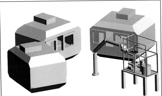
Figure 1.8 Illustration of the general model of the envisioned rapid prototyping center:
A cluster of three milling machines surround the universal automated fixturing sys-tem. A robotic arm transports the workpiece back and forth between the milling
machines and the encapsulation fixturing system.
universal fixturing system that is being proposed, discussed in the coming chapters, will allow one to fixture and machine two completely different parts in the same setup, using the same machine tool. In essence, with this fixturing system, one will be able to apply mass production techniques and optimization to prototyping situations. A fixturing sys-tem that allows one to transform unique, arbitrary parts into one generic norm, gives one the freedom to machine all those parts as if they were the same, transforming a cluster of machine tools, meant to run one-off parts, into a machining cell. Such a system, shown in Figure 1.8, would revolutionize the way engineers and designers think about product development and manufacturing. Just as the concepts of mass production--assembly lines, interchangeable parts--have revolutionize manufacturing, so shall rapid prototyping
Development of an Encapsulation Process for use in a Universal Automated Fixturing System
through machine tools. The ability to create one part as quickly, efficiently, and as eco-nomically as creating a thousand of those parts, that is the next frontier in manufacturing and product development.
Development of an Encapsulation Process for use in a Universal Automated Fixturing System
Chapter 2:
The Encapsulation Process and its
Application Towards Fixturing
In designing the universal fixturing system, it has been decided to develop the system using phase change fixturing techniques. Although extremely design intensive, it has, by far, the most potential to succeed. As mentioned in the previous section, the use of a phase changing encapsulation process has many disadvantages and hurdles to overcome.
Professor Sanjay Sarma describes many of these problems and possible solutions in his doctoral work at the University of California, at Berkeley.
One of the fundamental challenges in using phase change encapsulation is that of locating and aligning a workpiece with pre-existing features. The common practice has been to use locating dies for which the features of the part are aligned to matching features specially machined into the die. Unfortunately, the use of the locating die essentially corrupts the system's ability to become automated and universal. For each new part, a
unique die must be designed and manufactured. Thus, our approach will steer way from the usage of locating dies and to, instead, develop a process plan which will allow us to locate the part by some other means. Again, the research Professor Sanjay Sarma
performed as part of his doctoral work at Berkeley in 1995, under Professor Paul Wright, which this research is built upon, had followed the same goal.
2.1 Basic Process Steps of Encapsulation
The process we have formulated, in its most abstract form, can be described as follows. A piece of stock, rough cut to the approximate dimensions of the finished
Development of an Encapsulation Process for use in a Universal Automated Fixturing System
product, is encapsulated in a lower melting temperature material, molded into a perfect rectangular block[Sarma 95]. This block is then placed inside the machining environment so that a machining procedure or part of one can be performed on the block. Being a block form, the fixturing within the machine tool is completely automatable. The machining procedure is usually, but not always, limited to one side of the block. The block is
removed once the first machining procedure is finished and the features that have been machined into the block are covered with the lower melting material in order to restore the block to its original rectangular block shape. Once remolding is complete, the block is placed into the machining center again so that additional features can be placed on the present or another side of the block. These the machining and refilling, are repeated until
all features have been machined into the block. After such time, the block is taken out of the machine tool, and its temperature raised to a temperature above the melting point of the encapsulator but lower than that of the original stock. After the entire volume of the encapsulator has been liquefied and has flowed off, the finished piece can be easily extracted [Sarma 95].
This process plan is a modification of the classical encapsulation technique described in chapter 1. We can avoid using locating dies by prohibiting features to exist in the
workpiece before encapsulation. Instead, the locational datums are taken from the precision molded walls of the encapsulation cube. All features machined into the block after the encapsulation is referenced from those walls. (Consequently, one important constraint of the re-encapsulation and restoration procedure is that it may not disturb the wall locations.) This modified encapsulation process also allows one to completely machine all and any features on a part from one of the six directions of access. Fixturing
Development of an Encapsulation Process for use in a Universal Automated Fixturing System
of a part can be easily automated. Each setup is identical to the ones previous to it. There is no need for specialized hard tooling.
Development of an Encapsulation Process for use in a Universal Automated Fixturing System
2.2
Work at Berkeley
The concepts developed at the University of California, Berkeley led to what Professor Sanjay Sarma had named RFPE, Reference Free Part Encapsulation. The basic process that he developed is essential what is shown in Encapsulation process steps. The key idea behind RFPE was to automate the fixturing process using encapsulation techniques but without the use of locating dies, hence the name "Reference Free." [Sarma 95] Sarma
proposed that only blocks without any machined featured be encapsulated. Since no features existed on the encapsulated blocks, the determination of their precise orientation and location was unnecessary. When the encapsulation assembly was placed into the machine tool and it's first features were machined into the stock, the molded walls of the encapsulation would be used to locate the part encapsulated within. Thus, as long as those
molded walls remained partially intact, the locational data of the fixturing setup would never be lost.
Professor Sarma also identified many of the problems that would hinder the
encapsulation process. Thermal drift, shrinkage during the molding process, and strength issues of the encapsulator were the three most critical hurdles. In order to combat these problems, he proposed variations in the RPFE process that would minimize their effects.
2.2.1 Thermal Drift
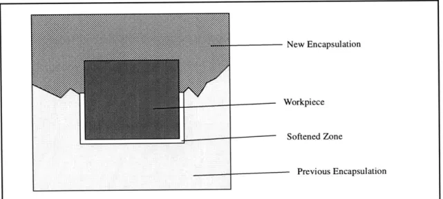
One of the major challenges to remolding a workpiece accurately was the thermal drift effect. During the remolding process, the newly introduced encapsulation material raises the temperature of its surrounding enough to soften the pre-existing encapsulator
surrounding the block. This softening allows the workpiece to shift a few thousands of an inch, thus destroying the accuracy/repeatability of the entire setup. This effect tends to
Development of an Encapsulation Process for use in a Universal Automated Fixturing System
occur when the encapsulator is a non-eutectic material. Having a broad phase transition temperature range instead of a sharp melting point, the encapsulator must be superheated far above the transition temperature range to insure that the encapsulator will readily flow when injected. When this superheated encapsulator comes into contact with the already encapsulated workpiece during a remolding stage, it raises the workpiece's temperature to
above the start of the phase transition temperature, allowing the existing encapsulator to soften. These effects are further exacerbated if the encapsulator possess a low thermal conductivity. Heat then becomes trapped inside the mold allowing the encapsulator to reach higher temperatures and remain there for an extended period.
New Encapsulation
- Workpiece
---- - Softened Zone
Previous Encapsulation
Figure 2.2 Illustration of the thermal drift effect during remolding
2.2.2 Deformation
The general trend of low melting temperature encapsulators is their lacks of strength and hardness compared to that of the workpiece they encapsulate. During milling procedures, deflection and deformation of workpiece and encapsulator is possible if it is not properly supported. However, deflection is usually minimized by the fact that the
Page 23 May, 1999
Development of an Encapsulation Process for use in a Universal Automated Fixturing System
surface area contacted between the workpiece and encapsulator is so large. [Sarma 95] There are no stress concentrations or point loads between the workpiece and encapsulator. Therefore, a feasible encapsulator can possess a yield strength and modulus considerably less than the stock that it encapsulates given that a sufficient amount of surface contact exists between the stock and the encapsulator.
2.2.3 Shrinkage
Another major challenge to maintaining accuracy in the molding is that of controlling shrinkage of the encapsulation material. Shrinking can cause pitting and sinks on the surfaces of the encapsulation and porosity inside. Also, the encapsulator tends to pull
itself way from the mold walls during the cooling process, creating bowed, curved surfaces which can not be used as locational datum planes. To solve this problem, the
encapsulation assembly can be subsequently machined after they are molded to flatten out their walls. However, these add steps to the overall process which are undesirable.
Development of an Encapsulation Process for use in a Universal Automated Fixturing System
Therefore, modified RFPE techniques were developed to combat this specific problem.Variations in RFPE.
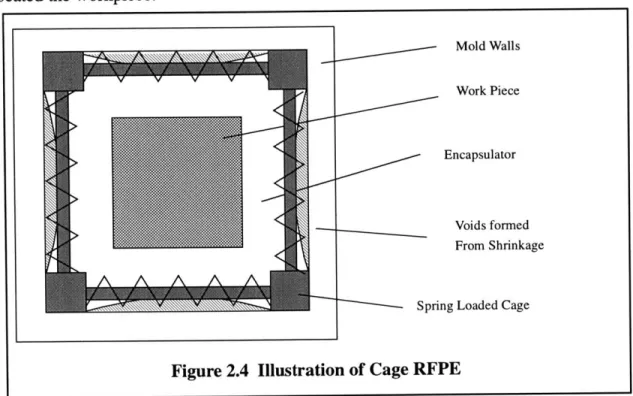
To combat the shrinkage problem, Sarma proposed two alternative methods for fixturing parts using encapsulation. Both techniques would no longer use the molded encapsulator walls as the reference datums. Instead, the "Cage" RFPE technique used a steel, spring loaded rectangular cage as a hard surface to locate off of. The springs on the cage would allow it to expand to conform to the mold. The encapsulator would be poured
into the molded and would retain the workpiece, supporting it between the cage struts. The shrinkage of the encapsulator was no longer a factor in determining the fixturing accuracy. The encapsulator served to support and immobilize but was no longer used to located the workpiece.
Mold walls
Work Piece
Encapsulator
Voids formed From Shrinkage
Spring Loaded Cage
Figure 2.4 Illustration of Cage RFPE
The second method was the called "Stock-Enclosed" RFPE [Sarma 95]. Like the cage version, it still used the encapsulator to support and immobilize the workpiece. However to locate the workpiece, it used the workpiece itself. The workpiece would, of course,
Page 25
Development of an Encapsulation Process for use in a Universal Automated Fixturing System
need to be machined into a perfect rectangular cube in order to use its walls as location datums. Then, features that were machined into the stock would refilled by pouring the encapsulator directly into the pocket machined into the stock.
Both of these methods have their limitations. Most notably, both reduce the
accessibility to the actual workpiece. The need to maintain a cage or stock around the encapsulator prohibits machining in several key directions. Also, the Stock Enclosed RFPE required that the stock be pre-machined into a block form before the actual machining process could begin, thus adding steps to the process.
2.3 Encapsulation in Industry
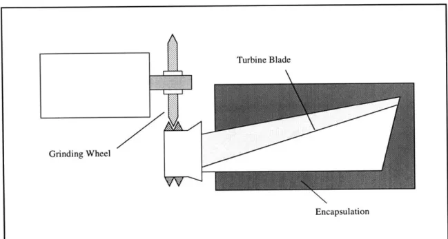
Phase change encapsulation fixturing is hardly a new idea in the machining and manufacturing industry. One of the most prevalent uses of phase changing fixturing is in the aerospace industry. Since the invention of the turbine engine, manufacturing the turbine blades have proven to be a particularly challenging task and fixturing these oddly shaped turbine blades for machining has obtained a fair amount of attention. Many of the industry's technological leaders have turned to encapsulation to fulfill their fixturing needs.
Pratt & Whitney's North Haven, Connecticut facilities uses a modified encapsulation process to fixture post-cast turbine blade in order to grind the tail feature that allow the
blades to be inserted into the main turbine hub. The plant itself was built in 1953 but only started to use encapsulation fixturing in the early 1970's. The entire factory floor is setup to handle every facet of encapsulation. Special workholding devices have been design to locate and hold the turbine blades before it is encapsulated. Each encapsulation cell is manned by one operator, inserting new blades into the workholding/molding device and
Development of an Encapsulation Process for use in a Universal Automated Fixturing System
removing an encapsulated one roughly every 5 seconds. These encapsulated blades are then moved to a different cell where they are automatically located and fixtured into a grinding machine. Once machined, they are then transported to the encapsulation removal stations. Loaded into a high pressure steam chamber, the encapsulation surrounding the turbine blades are melted off and then inspected for residue [Sprenkle 96].
2.4 Material Selection
One of the key factors to the success of designing an autonomous fixturing system using encapsulation is the selection of the encapsulating material, the encapsulator. Thus far, the materials that have been investigated are fixturing polymers such as RigidaxTM and FreemanTM machinable wax, fusible alloys such as alloys of tin and bismuth, and various types of higher melting temperature engineering plastics such as acetels, acrylics, nylons,
and polycarbonates. In choosing the encapsulator, one has to take into account the
Page 27 May, 1999
Encapsulation
Figure 2.5 Encapsulating turbine blade for machining processes allows a less complex fixturing system to accommodate odd geometries.
Development of an Encapsulation Process for use in a Universal Automated Fixturing System
hardness and stiffness of the material, its machinability, its thermal conductivity and moldability, the quality of its adhesion to the workpiece, its melting temperature, its coefficient of thermal expansion, its ease of reclaim, the stability of these properties after
numerous reclaims, and, of course, its price and its safeness.
2.4.1 Selection Criteria
The primary objective in selecting an encapsulator is to minimize the molding cycle times while also maximizing the quality of the moldings. The quality of the molding can be defined by many parameters. It can be define through such metrics as the accuracy and the level of surface finish attainable through molding and through machining once
encapsulated. Furthermore, these two objectives are balanced by a third, that of
minimizing the cost of support equipment, such as the injection machine, that must handle and deliver the encapsulator. And of course, all these considerations are blanketed with the need to produce a safe and healthy working environment.
The material properties that we have identified to be important are the following: 'Yield Strength/Young's Modulus-For precision machining, the encapsulator should have a high Young's modulus, but have a fairly low yield strength. This allows the encapsulator to be more machinable while also minimizing the errors in deflection caused by the cutting forces in the machining process.
'Thermal Conductivity-A high thermal conductivity aids in cooling the encapsulator quickly once molded, allowing the molding cycle time to be reduced. However, high conductivity will result in a high rate of heat loss and a likelihood of freezing during the molding process if it comes into contact with a cold surface. This can result in
short shoots or scarred surfaces. Maintaining a warm mold will thus be a functional requirement of the molding system if a high conductivity encapsulator is used. This shall be discussed later, in Chapter 3.
Development of an Encapsulation Process for use in a Universal Automated Fixturing System
-Viscosity-A low viscosity allows for easier delivery of the encapsulator to the mold at lower temperatures. Less pressure would be needed to deliver the encapsulator, thus reducing the cost of the injection piston system.
-Melting Temperature-A lower encapsulator melting temperature allows for less complex molding devices. Since the temperatures on the mold and delivery systems do not need to reach as high, there can be less insulation around the heaters, and the heaters themselves need not be so large or use as much power. In addition, since machining is performed on the encapsulation assembly at room temperature, a lower
melting temperature reduces the temperature change the encapsulation must endure between molding and machining. This reduces the effects of thermal strains caused by the mismatch in the coefficients of thermal expansion, between the encapsulator and the stock within.
-Eutectic/Non-Eutectic-Eutectic encapsulators have obvious advantages in terms of avoiding the problem described in Section Thermal Drift. The encapsulator need not be super heated to ensure low viscosity during injection and subsequently would not
soften existing encapsulator that already surround the workpiece. However, there are drawbacks in using an eutectic alloy. Most notably is the sealing, dipping difficulties and the flash that arise around mold mating surfaces. Eutectics exhibit a sharp change in viscosity at its melting temperature. It is very difficult to control a eutectic's viscosity through temperature. Eutectics can, thus, only be used in either a hard solid which will not flow and a low viscosity liquid that will readily flow. On the other hand, a non-eutectic alloy's viscosity, because it has a melting range where it gradually
softens with the increase in its temperature, can be control quite easily through temperature. The alloy could be injected at a temperature where it was a fairly viscous
liquid and thus would not readily drip or flash. Encapsulation using a higher viscosity encapsulator would allow less stringent flatness specifications on mold mating surfaces. And when the mold is open, the surface tension of the high viscosity
encapsulator would be enough to prevent dripping from the gates, reducing the need to design in a valve at the gates.
Development of an Encapsulation Process for use in a Universal Automated Fixturing System
*Coefficient of Thermal Expansion-As stated in section Shrinkage, it is
advantageous to minimize the coefficient of thermal expansion in order to reduce shrinkage after cooling. In fact, the encapsulators should be formulated with a slightly negative CTE's so that blocks will expand to fit the molds more accurately upon cooling.
*Chemical Interaction-It is important that the encapsulator can be fully melted away from the workpiece once all the milling operations have been performed. The
encapsulator must not disturb the surface finish of the finished part, alter its molecular state, or become permanently bonded to the workpiece. Trace amounts of the
encapsulator in the workpiece can render the part unless for its intended application. -Damping-Encapsulators that can add extra damping to the fixturing system will reduce chatter during machining and thus increase the overall accuracy of the
machining process.
'Safety and Health-Besides obvious reason, an encapsulator should be chosen such that it does not possess particular danger to those who work with it because it will increase system and process costs and complexity. Dangerous materials require special equipment to handle and treat it. Cleaning apparatus needs to be installed to insure that waste from the process does not infect the environment. And a variety of
safeguards must be set in place to deal with accidents and mishaps.
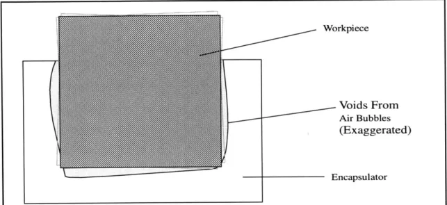
'Surface Energy/Adhesive Properties- Lastly, a less obvious material property is that of the quality of adhesion of the encapsulator to the stock. Without fairly good contact between the encapsulator and the workpiece, gaps will form from trapped air bubbles and shrinkage. When machining is done, capillary action will tend to suck machining coolant between the block and the encapsulator. As a result, the block will float slightly and jitter as it is machined. Good adhesion between the block and the
Development of an Encapsulation Process for use in a Universal Automated Fixturing System
encapsulator will prevent this by firmly anchoring the workpiece to the encapsulator and ensuring good contact.
Workpiece
Voids From
Air Bubbles
(Exaggerated)
Encapsulator
Figure 2.6 Illustration of voids that are often formed by trapped air bubbles or shrinkage of the encapsulator
2.4.2 Fusible Alloys
This research has primarily relied on a Bismuth/Tin eutectic alloy for encapsulation. Widely available, this eutectic binary alloy is composed of 58% Bismuth and 42% Tin. The alloy has a low melting point of 281 degrees Fahrenheit. It has a reasonably high Young's Modulus of 7.5GPa and an adequate yield strength of 60MPa. It's thermal
conductivity is 18.4 W/m*K. It's thermal expansion efficient is 15 e-6/ 'K. It has very good stability. It's main detractor is that it has a high surface energy and thus will not easily wet most metallic materials and other materials that will easily oxidize. Methods for combating this problem will be discuss later in chapter 5.
Tin/Bismuth alloys fall wintin a braod class of alloys called fusible alloys which are low melting temperature metallic alloys. In general, they are used as solders. Most contain lead and many contain cadmium. Both lead and cadmium are carcinogenic. Thus
Development of an Encapsulation Process for use in a Universal Automated Fixturing System
developing an encapsulation process using an alloy composed of either will not only become extremely hazardous but also cumbersome to the process. Many safety
regulations and guideline must be followed to the letter. Thus, the encapsulation alloy was chosen specifically because it contains no substantial amounts of lead or cadmium. The fact that it also happens to be an eutectic and matches may of the other criterions is
fortuitous. There are other combinations of the bismuth/tin binary alloy that are
potentially useful in our study. There is a 40/60 bismuth/tin alloy that possesses a melting range on 281*F to 335'F. It has many merits as well to our application that the eutectic does not possess. For example, its thermal conductivity is twice a large, at about 29.6 W/ m0K. The growth and shrinkage of the 40/60 alloy is also significantly different. There has been little experimentation performed on the 40/60 alloy. It will be interesting to
observe its performance. We shall pursue this at a later time.
2.4.3 Fixturing Polymers
While fixturing polymers can be easily machined, melt at low temperatures and provide considerable damping to the fixturing system, they have low thermal conductivity, high shrinkage, and very poor mechanical strength. Maintaining a good surface quality on such
a soft material would be extremely difficult if not impossible. The low conductivity and high shrinkage often causes sinks and bows on the surface of the moldings. What is more, there is a severe thermal expansion mismatch between the machinable polymers and most metals that will cause the encapsulation to crack and disintegrate upon cooling around its workpiece. The RigidaxTM machinable polymers possess fairly good adhesive qualities, adhering to metals and other materials reasonably well. However, this visco-elastic and
Development of an Encapsulation Process for use in a Universal Automated Fixturing System
adhesive effect causes the material to gum up endmill flutes and results in poor machinability. For this application, fixturing polymers has proved to be unattractive.
2.4.4 Engineering Plastics
Engineering thermoplastics, which have been used in industry as injection molding materials, are not much better suited for encapsulation. Their high shrinkage is a major detractor. While this high shrinkage can be alleviated by using a packing routine during the encapsulation/injection process, sinks and bows are still visible when the thickness of injected parts becomes substantial. While their mechanical properties are very appealing,
they are non-eutectic and have very high melting temperatures. NylonsTM melt at 440'F and Actels(DelrinTM), 495*F. Their thermal conductivity is low, averaging about 2.3 W/
m*K. And in general, they are difficult to machine compared to the other two material types. Their high strengths generate considerable heat which can not be dissipated due to their low thermal conductivity. As a result, endmill flutes often cog when the material removal rate is too high.
2.5
Advantages of Encapsulation Over other Fixturing
Methods
Having familiarized ourselves with encapsulation as a fixturing process, it is appropriate to return to the beginning and develop the reasons for developing our
universal fixturing system using phase change fixturing methods. Within this section, the focus shall be to discuss the advantages of fixturing through encapsulation and its ability to accomplish tasks that no other fixturing process could.
Development of an Encapsulation Process for use in a Universal Automated Fixturing System
2.5.1 Ease of Automation
Encapsulating the raw stock constrains the part shape to a generic norm, in this case a rectangular block with perfectly perpendicular walls. This constraint allows for a more intelligent workholding design. It allows one to easily design an algorithm that will carry
out accurate/repeatable workholding of any arbitrarily shaped part. References are continuously maintained during setup changes using the boundaries of the filler block, which are independent of part features. Working holding can thus be easily automated since the fixturing system need only interact with that one generic norm and not thousands of different geometries.
2.5.2 Machining Thin Members and Odd Shapes
Encapsulation can be used to fixture almost any arbitrary shape. Delicate features, such as spring elements, ribs, and thin walls, can be machined. Encapsulation fixturing gives us the ability to machine features onto those spring elements without worry of deflection or deformation of those features. As shown in Illustration showing toolpaths for
machining special elements with the aid of encapsulation fixturing, the encapsulation can be filled so that it directly supports the feature while it is being machined. The
encapsulator can fully support thin elements regardless of their location within the workpiece. For these special features, the remolding pattern must be carefully planned. Only one side of the feature can be cut in one pass. The workpiece must be remolded and the feature refilled before machining can proceed to the next side. It should not be difficult to create CAD/CAM programs to identify these thin features, which have large length to width ratios, and automatically plan the proper tool paths and remolding
sequences. This innovative CAM scheme is discussed more in chapter 5.
Development of an Encapsulation Process for use in a Universal Automated Fixturing System
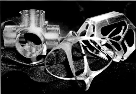
Photo taken by Elmer Lee
Figure 2.7 Photograph of sample parts machined using encapsulation fixturing:
Parts are made of AL 6061-T6 on a 3 axis Cincinnati Milicron 7VC
Parts that once needed to be machined separately, because of fixturing constraint, and then assembled later, can now be machine out of one piece, cutting assembly time and costs. Ordinarily, the three tube elements shown in the back left in Photograph of sample parts machined using encapsulation fixturing: would be machined separately and then welded together. Here, encapsulation allows the machining of all three tube elements from the same piece of stock. The tube walls are all less than 0.01" thick and more than
1.00" high. The orb shaped part, shown in the front in Photograph of sample parts machined using encapsulation fixturing:, and the intricate webbed part shown right back in Photograph of sample parts machined using encapsulation fixturing: were both manufactured on a 3 axis milling machine, out of a single piece of stock, despite their delicate spars. Without encapsulation, both parts would be extremely difficult to fixture
Development of an Encapsulation Process for use in a Universal Automated Fixturing System
Development of an Encapsulation Process for use in a Universal Automated Fixturing System
and machine. Most likely, more expensive, time consuming manufacturing methods, such as wired electro-discharge machining, would have been used to manufacture these parts had encapsulation fixturing not been available.
2.5.3 Developing manufacturing processes without hard tooling
While this encapsulation fixturing process was never designed to replace hard tooling in a mass production environment, it can be used during the preliminary stages when
developing a mass production facility. During the preliminary testing of a manufacturing plant, machine tools and other equipment are constantly being changed and retrofitted in order to optimize plant and increase the production rate and efficiency. Unfortunately, while machines can usually be sold or redistributed to others parts of the plant, changes in the plant layout usually result in changing to new types of tooling and fixturing system, leaving the old hard tooling, that was specifically designed for that single process, useless.
Instead, manufacturing engineering can develop their processes using the same universal fixturing we are developing. Once the machines and support equipment have been debugged, the encapsulation fixturing can be replace with permanent hard tooling. Such a practice removes the possibility of scrapping a piece of hard tooling because of equipment changes.
2.5.4 Machining Parts in Small Batch Sizes
The next frontier in manufacturing is likely to be in single part production, that of producing goods customized to the individual, on demand. It will be the ability to
manufacture one part as inexpensively and as efficiently as one thousand parts that will revolutionize the industry. An automated universal fixturing system will play an important role in achieve these goals.
Development of an Encapsulation Process for use in a Universal Automated Fixturing System
Developing our fixturing system through encapsulation brings us one step closer to those goals. Once encapsulated, different parts are treated by the workholding device as the same. Thus, multiple parts can be machined in the same fixturing setup. There is no need to change setups and there will be no down time for the machine. With
encapsulation, we can turn a mass production machine into a rapid prototyping machine.
Customer A
Customer B
May, 1999
| - Unique G code
Figure 2.9 Illustration of encapsulation fixture's ability to transform 2 different parts into one generic norm:
Once Encapsulated, "the black box" can treat customer A and customer B's parts as identical. Their only difference will be the G-code needed to control the "black box."
Depending on the G-code, either part can be manufactured with equal ease.
BIlack Box
**-
R
Page 38 0-OF-Developement of an Encapsulation Process for use in a Universal Automated Fixturing System
Chapter 3:
Design Process of an Encapsulation
System for Fixturing Applications
This chapter describes the process by which the encapsulation machine has been designed. It shows the train of thought and logic, and illustrates some of the key design paradigms which were adopted. The design problem was organized in terms of functional requirements and their corresponding design parameters to separate this large complex design problem into parts which are smaller and more tractable.
3.1 Primary Functional Requirements
The first step in any design process is to identify the key problem(s) and hurdle(s). I have done so by identifying the functional requirements(FR) of the design [Suh 90]. It is important to note that at this stage of the design, only the problem is discussed. We will do our best to keep solutions to those problems, or design parameters, out of our thoughts and efforts at this point. Of course, it will also be important to make certain assumptions to limit the focus of our problem. Otherwise, the design process will be overly
complicated with superficial details.
Furthermore, these functional requirements have been organized in a hierarchical manner, moving from general functional requirements to more specific ones. In this manner, it will be easy to separate those functions that are related or dependent on each other and those that are not.
For the design of an encapsulation machine, the primary functional requirements are as shown.
Developement of an Encapsulation Process for use in a Universal Automated Fixturing System
- Melt the Encapsulator and Store it for use
In order to be used, the encapsulator must be transformed from its solid form to its liquid form. Assuming that heating will not be quick enough such that each shot can be melted just prior to injection, a fair amount of the
encapsulator will have to be melted and kept molten until it is ready for use.
- Deliver the Molten Encapsulator from the storage unit to the molding device
Assuming that the storage unit and the molding unit will be separated, it will be necessary to transport the encapsulator from one to the other.
Considerations such as how to maintain the encapsulator molten, what pressure is needed to be delivered and how quickly need it be delivered are
all sub FR's that will be considered later.
- Mold the encapsulator
Though fairly obvious, this functional requirement will have a great many sub FR's that further divides this part into smaller parts of the design. This FR should be subdivided into other FR's dealing with the molds, the clamping device, and the interface with the delivery system.
It should be noted that decoupling a design into different FR's is purely for the designer's convenience and is done solely at the designer's discretion. There is no absolute algorithm on how to separate FR's and sub FR's (there are, of course, better and worse ways to develop them). One can expect, for any given design problem, that two
designers can choose to decouple the functional requirements in different manners, each leading to a viable design solution.
I have chosen to decouple the encapsulating machine into three parts based on considerable experimental experience and intuition. You will see, later on, that each of
Developement of an Encapsulation Process for use in a Universal Automated Fixturing System
these three functional requirements are transformed into three easily distinguished design units or machines. I find that designing by drawing boundaries that delineate the overall design into smaller more manageable unit allows me to design one part without too much concern for the functions of the rest of the machine. This, of course, is artificial. For any process or machine design, all its parts must function harmoniously, communicating with each other at all times. To design one unit of a machine without any consideration of the other parts would be foolish.
Nonetheless, the decoupling of the functions of a machine does allow one to satisfy one function at a time by imagining that the rest of the design remains given and fixed. Afterwards, one can move on to another function in much the same fashion. However, it
is necessary to revisit the previous functional requirements to assure that no conflict has risen and that all the functional requirements still remain satisfied. Thus, this design process can be thought of, not as one pass approach, but as an iterative one.
3.2 Expanding into Sub-Functional Requirements
Now that we have laid down the overall scheme of the machine, that is separated the machine into its key components, we will then tackle each individually. It is necessary to elaborate on each of the primary functional requirements and to build a more complete list
of the tasks each units must accomplish. They are as shown below.
3.2.1 Melting the Encapsulator and Store it for use The sub-functional requirements are:
- Allow for fast warm up
The melting of the encapsulator will not directly effect the molding cycle time of the entire machine. Nonetheless, the warm up time should not be
Developement of an Encapsulation Process for use in a Universal Automated Fixturing System
extraordinarily long or it will become burdensome during production in cases when the system must be powered down and restarted, as on occasions when cleaning and maintenance work must be down. Though not a concrete number, setup times of about 1 or 2 hour would be acceptable.
- Easily maintained and serviced
Over the life of the machine, it will of course need to be maintained and serviced. When a different encapsulator must be used, it will be necessary to purge the system of the previous encapsulator material. Thus, ease of removal of the encapsulator and cleaning will be a clear performance
attribute. While this functional requirement will need to be discussed for all parts of the machine, the transfer unit and the molding unit, it will be focused in this unit of the machine because the bulk of the material will remain in the storage area.
3.2.2 Deliver the Molten Encapsulator from the storage unit to the molding device - Ensure that transfer line never freezes up-that flow is always maintained Because the encapsulator that will be usually employ in the encapsulation
process is a metallic alloy, having a high thermal conductivity, it will readily lose heat upon contacting a cold surface. Freezing and lockup of the transfer line will thus be a key concern and a major problem to overcome.
- Facilitate molding using pressure
It will be necessary to perform the molding under pressure. This will improve the surface finish of the molding by allowing the encapsulator to conform to the mold and workpiece surfaces more accurately. Molding under pressure will minimize the shrinking of the encapsulation. It will allow the mold to be fill quicker and the molded to be designed using smaller gate sizes, thus allowing the encapsulation assembly to be more easily removed from the mold. Our experiments have shown that the use of
Developement of an Encapsulation Process for use in a Universal Automated Fixturing System
pressure is vital to improving the accuracies of the molding and the overall performance of the fixturing process. The advantages of molding under pressure will be further discussed in later sections.
3.2.3 Mold the encapsulator
- Ensure Safety and Economy
We must ensure that the molds seals properly and that no spillage occurs. It will also be necessary to insulate the heaters to conserve heat energy and prevent accidental burning of the operators should he touch the hot surfaces.
- Maintain a Low Cycle time
The cost and utility of a machine is directly dependent on its cycle time. The faster a machine can produce a particular item, the more useful and
worthwhile it will be to purchase. Thus, optimizing the machine so that its cycle time is as low as possible is another key task. To do so we must examine the cycle itself. Within the cycle, stock must be delivered and placed inside the mold, the mold must be heated to the desire temperature, the mold must be securely closed, the encapsulation must be at the proper temperature and ready to be delivered. Once the mold is closed and secure, the encapsulation needs to be delivered. Once filled, the encapsulation and
the mold need to be cooled to the proper temperature, and then extracted from the mold. Finally, the mold must be made ready to accept the next piece of stock. From these steps, we can develop more precise functional requirements that have the effect of reducing the cycle time. These are shown below.
* Fast thermal cycles of the molds
Here we must consider the heater and cooling plate placement. We must place thermal sensors as close to the targeted area to reduce thermal abbe errors. We must prevent the gates from freezing up, else they will need to be remelted or cleared before the next cycle begins. And we must minimize the
temperature change the mold must experience with in a cycle.