Development of
an Integrated Capillary valve-based Preconcentrator
and a Surface-based Immunoassay
by
Vincent Hok Liu
MAsSACHUSE- S INS1I rUTE
MAR 0 5 2309
LI
3
ARI-B.S. Electrical Engineering and Computer Sciences, 2006
University of California, Berkeley
Submitted to the Department of Electrical Engineering and Computer
Science in partial fulfillment of the requirements for the degree of
Masters of Science in Electrical Engineering and Computer Science
at the
MASSACHUSETTS INSTITUTE OF TECHNOLOGY
February 2009
© Massachusetts Institute of Technology 2009. All rights reserved.
Signature of Author:
Dc
Certified by:
epartment of Electrical Engineering and Computer Science
/ ' V
Associate Professor of Electrical Engineering
Accepted by:
_.
Jauarfy 3_0
t, 2009
---
ngyOon Han
and Computer Science
Thesis Supervisor
Terry P. Orlando
Professor of Electrical Engineering and Computer Science
Chairman, Committee on Graduate Students
Development of
an Integrated Capillary valve-based Preconcentrator
and a Surface-based Immunoassay
by
Vincent Hok Liu
Submitted to the Department of Electrical Engineering and Compute Science on
1/30/2009, in partial fulfillment of the
requirements for the degree of
Masters of Science in Electrical Engineering and Computer Science
Abstract
A new generation of integrated preconcentrator and immunoassay was
developed. A novel, self-aligned method for patterning Nafion resin was developed
and applied to create a preconcentrator. In a parallel effort, a surface-based
immunoassay was developed and optimized for use with the preconcentrator.
Experiments were carried out with R-phycoerythrin (R-PE) to characterize
the performance of the integrated preconcentrator and immunoassay. The
immunoassay originally has a detection limit of Ing/mL of R-PE in 1xPBS. When
coupled to the preconcentrator, this limit has been improved to 0.Olng/mL, a
roughly 100x improvement. Discussions of the differences between this and
previous generations of concentrators are also presented in this thesis.
Thesis supervisor: Jongyoon Han
Acknowledgments
I would like to thank Professor Han for being my research mentor and teacher. His vision, passion, and work ethics have encouraged me to try different approaches to
experimentation and keep an open mind for different techniques. I am especially appreciative of his guidance when planning experiments and his discussions on the future directions of my
research.
I would also like to thank Ying-Chih Wang for helping me with my research, especially during the initial phrases of my graduate work. Other lab members, including Yong-Ak Song, Leon Li, Aniruddh Sarkar, and Lih Feng Cheow, have been supportive of my efforts in the lab and have become my good friends. I also enjoyed working with the staff member at MTL in fabricating my devices.
Last but not least, I am grateful for my friends and family who encouraged and supported me in college and graduate school. They are the ones who helped me become who I am today and encouraged me to do what interested me.
This work would not be possible without the funding support of the National Cancer Institute (RO 1-CA 119402).
Contents
1. Introduction
9
Plasma proteomics and their implications in clinical diagnostics 9
Current clinical diagnostics techniques and equipment 10
Microfluidics immunoassay, SPR, electrochemical methods, and more 10
Microfluidic Signal Enhancement- pre and post binding 11
Outline of thesis 12
2. Biomolecule Immobilization
13
Introduction 13
Covalent attachment methods 14
Silanization 14
Physical absorption 15
Direct absorption 15
Bioaffinity systems 15
Combining the two 17
Use in concentrator system 18
Optimizing immobilization conditions 18
Selective protein patterning 20
Microcontact stamping 22
Hydrophobic microvalves 24
3. Device Fabrication
27
PDMS Device fabrication 27
Remark: Ionic strength and ion depletion 28 Ion-exchange membrane - Nafion in microfluidic devices 28
Capillary valves 30
High aspect ratio membrane with capillary valves 31 Differences between multiple and single channels 35 Differences between single and double gates 35
Filling channels 37
Remark: Making double-gated multi-channel devices 39 Characterization - pressure driven flow, 1xPBS 39
4. Device characterization and Immunoassay
42
Biological recognition 42
Binding kinetics 43
Microfluidic assays 43
Microchannel dynamics and design 44
Experimental protocols 46
Reagents 46
PBS Buffer 46
Surface functionalization 47
Remark: Non-specific absorption 47
Voltage 47
Illumination 47
Remark: Methods of illumination 48
Microscope 48
Data acquisition and processing 48
Immunoassay with R-Phycoerythrin 48
Remark: Syringes 49
Immunoassay results 49
Preconcentration experiments 51
"Dot" based preconcentration 52
Preconcentration results 54
Tracer for low concentration and non-fluorescent molecules 55 Challenges for using non-fluorescent molecules 56 Challenges for using serum/biological fluids 57
5.
Conclusion and Future Work
58
Chapter 1
Introduction
Plasma proteomics and their implications in clinical diagnostics
Plasma, or the liquid component of blood with the blood cells removed, remain one of the most important and clinically obtainable specimens. It also represents the largest and deepest human proteome that's present. Specifically, plasma contains abundant proteins such as albumin, tissue leakage proteins such as tissue damage markers, and local signaling proteins such as cytokines [1]. Given the diversity of proteins present in the serum and plasma, it's not surprising that many clinical tests rely on the accurate detection and quantification of serum/plasma
proteins. Tissue leakage proteins are important because a small amount of proteins leaked into the plasma from an organ can represent a significant pathological state in the local organ. For example, cardiac myoglobin is present in a range of 1-85ng/mL in healthy individuals, but the concentration rises to 200-1100ng/mL in a person with active cardiac infarction. [1] An important class of local signaling proteins is called cytokines, which includes indictors of inflammation or infection. These proteins act as local signaling agents between cells, but are detectable in plasma at much lower concentrations after it has been diluted into a systemic level [1]. While genomic techniques, such as DNA or mRNA microarrays, have made significant inroads into both biological research and clinical diagnostics, genomic expression does not always correspond to the protein content found in serum or plasma. The reasons for this include post-translational modifications and protein-protein interactions. This made plasma protein levels the ideal candidate for diagnosing/detecting protein-based biomarkers. [2]
The large dynamic range of proteins raise an interesting challenge - the ability to design a technology that can detect high abundance proteins as wells as low abundance ones would certainly be useful in a clinical setting. The ideal system would be able to measure protein levels down to sub pg/mL concentration, while at the same time maintain the ability to detect higher abundance molecules. Also, recent research has shown that complex, systemic diseases such as cancer affect multiple protein products simultaneously, and measuring a single biomarker has not been as effective an indication of disease progress as previously thought. [3] As most sensors have a limited dynamic range of around 4 to 5 orders of magnitude, they don't have the capability to cover the entire proteome (about 10 orders of magnitude), and a better method to improve sensitivity and extend the dynamic range is needed. We are currently attempting to direct efforts in the lab to address this problem by locally increasing the concentration of low abundance proteins and thus resulting in a larger dynamic range available for detection and to improve the detection of clinically relevant markers.
Current clinical diagnostics techniques and equipment
Current methods of quantifying concentrations of proteins in biological samples involve various immunological methods as well as technologies that are derived from analytical
chemistry, such as mass spectrometry.
The immunoassay remains one of the most popular methods for detecting pathogens in clinical samples and in research labs. Immunoassays rely on antibodies that are immobilized to a solid phase/surface to capture antigens that are suspended in solution/the mobile phase. Antigens that react with immobilized antibodies would be captured and immobilized together with the antibodies on the surface of the chip. A wash step follows to remove unbound antigens and the bound antigens can be quantified using fluorometric, electrochemical, or radioactive methods. [4]
Enzyme-linked Immunosorbent Assay, or ELISA, takes the concept of the immunoassay one step further by adding an amplification step after the antigen binding step. Instead of a secondary antibody with a simple fluorescent/radioactive tag, the secondary antibody is tagged with an enzyme, such as Horseradish peroxidase or alkaline phosphatase. After the secondary antibody is attached, substrates for the enzyme is flowed mixed with the bound complex. The enzyme attached to the antibody would react with the substrate and generate a signal in the form of a fluorophore; since the enzyme would continually generate additional fluorescence over time, the original signal is amplified over time and allow for more sensitivity detection of analytes in solution. [4]
A second technology that's currently used for detecting pathogens is mass spectrometry. Proteins carry specific mass signatures because of the unique combinations of components contained in their structure, and mass spectrometry achieves detection of specific proteins by comparing the signature to an established database of different proteins. The advantage of mass spectrometry is that it can analyze a number of different proteins at the same time, i.e. profile the protein contents in human serum. A number of complex, systemic diseases are usually best characterized by a panel of different proteins. Diseases such as cancer alter the concentration and conformation of a number of proteins, and the expression profile of proteins often contain useful information about disease progress and details of the disease itself.
These techniques are now quite well established in the diagnostics industry and have become the standard for clinical diagnostics tools. However, most of these techniques require labor-intensive work, are prone to human error, and are time consuming. The development of microfluidics assays, or "lab-on-a-chip" devices holds the promise of alleviating many of these problems, and some of these development would be detailed in the next section.
Microfluidics immunoassay, SPR, electrochemical methods, and more
There has been tremendous progress made on the design, fabrication, and usage of microfluidics devices over the past decade. Microfluidic devices offer the advantage of miniaturization, which reduces reagent consumption, and automation by integrating multiple processes. These devices reduce the frequency of human errors and ensure better repeatability as well as better sensitivity. Microfluidics-based assays also have the advantages of decreased assay time and thus opening the door to the use of these assays in a point-of-care setting.
A variety of materials are used to fabricate microfluidics devices, including silicon, pyrex, and polymers such as PDMS and PMMA. Regardless of the material used, antibodies need to be attached to the microchannel to capture analytes of interest. There are a number of ways to immobilize antibodies in a microfluidics channel - by attaching them to the
microchannel surface or by immobilizing antibody-loaded beads in the microchannel. A number of different protocols, including physiosorption, chemisorption, and covalent linkages, have been investigated to immobilize antibodies onto the channel surface [5]. Similarly, a number of
different bead trap designs have been proposed in the literature, including weir shaped structures that physically trap beads and chips that integrate magnets to traps and release beads. [6]
Other assay technologies that have been developed on microfluidics platforms include Surface Plasmon Resonance (SPR) and a number of electrochemical techniques. These technologies boost advantages such as label-free detection, real time kinetics monitoring, and excellent sensitivity. SPR works by measuring changes in a material's refractive index to light. Molecular binding events, such as antigen binding by antibodies that are bound on the surface, changes the surface's refractive index and thus reports a signal to the sensor. [7] Electrochemical methods include potentiometric (voltage sensing), amperometric (current sensing) and others. Typically, electrodes or microchannels are functionalized with antibodies, and binding events would cause a change in the resistivity of the buffer and thus transduce a signal to the sensor. [8] These sensors have the advantage of being inherently more integrable with microelectronics than sensors that rely on fluorescence readouts. However, the lack of good and established
amplification methods limited the popularity of electrochemical sensors.
Miniturized systems often integrate sample preparation processes as well as the assays. In the next section, signal amplification and preconcentration processes that can be integrated with the assays are described and reviewed.
Microfluidic Signal Enhancement- pre and post binding
Due to the biological significance of low abundance proteins, a host of amplification methods have been developed both in microfluidics. Signals from molecular recognition events
can be amplified in two ways: before binding and after binding. Most of the pre-binding signal enhancement focuses on increasing the number of molecules that would bind to capture
antibodies, and post-binding signal enhancement increases signal output from molecules that are already immobilized. In this section, techniques amendable to use in microfluidics chips are discussed along with the technologies developed in our lab
There are a number of ways to preconcentrate sample molecules before they react with the capture antibodies. Field amplified stacking works by having a low conductivity buffer
sandwiched between two buffers with higher conductivity. When a voltage is applied, the high electric fields in the low conductivity buffer stack the molecules against the boundary of the zone. [9] This is similar to isotachophoresis, where a gradient of molecules with different electrophoretic mobilities are stacked with respective to a gradient generated in steady state. These techniques establish a concentrating zone using properties of the buffer, which requires tedious buffer exchange and limitations of buffer compatibility. One of the solutions is to use electrokinetic manipulations, such as that developed in our lab, to perform preconcentration. This technique also doesn't require the use of prefabricated membranes or special structures in the microchannels.
Post binding signal enhancement increases signal generated by captured molecules by increasing their fluorescence intensity or other readout signals. The classical post-binding amplification method is ELISA, which relies on enzymatic activities to progressively increase the signal strength after binding of the secondary antibody. Recently, Schweitzer et. al. have reported the use of rolling circle amplification (RCA) as a sensitive and specific way to amplify signals from bound molecules [10]. The advantage of pre-binding amplification is that both sensor sensitivity and binding kinetics would be improved, leading to both faster and more sensitive assay.
Though not discussed here, new sensor designs and detection mechanisms also help lower detection limits and dynamic range of diagnostic technologies. Ultimately, pre-binding and post-binding signal enhancement technologies can be combined so that the detection limit can be pushed to even lower than either one can achieve by itself.
Outline of thesis
In this thesis, I will describe the development of a surface-based immunoassay for detecting both fluorescent and non-fluorescent molecules present physiological ionic strength. Subsequent chapters would detail biomolecules immobilization, device fabrication, and device characterization. More specifically, Chapter 2 will be devoted to various surface chemistries and functionalization schemes. Device fabrication and Nafion membrane formation would be
discussed in Chapter 3, and I will describe device characterization and immunoassay enhancement in Chapter 4. Finally, future outlook and research directions are proposed.
Chapter 2
Biomolecule Immobilization
Introduction
Separation technologies are at the heart of immunoassays. In heterogeneous
immunoassays, unbound analytes that are in solution need to be separated from analytes that are bound to capture agents, such that only bound analytes remain at the signal generation and detection stage [13]. If there's a failure to remove all of the unbound analytes, the quality of assay would suffer as these unbound analytes would interfere with subsequent introduction of secondary antibodies or detection.
There are multiple methods to perform separation of bound/unbound analytes. Liquid phase separation involves the use of electrophoresis, size exclusion chromatography, or precipitation to separate antibody-bound analyte from unbound analytes [13]. Most of these methods are nonspecific and can be affected by the concentration of protein in the sample, resulting in poor predictability and performance. [13] Another method for separation is for capture agents to be immobilized on a solid/insoluble support structure. Since captured
molecules would no longer be in free solution, it becomes possible to specifically separate the analyte that are bound to the solid phase from those that remain in solution.
A number of methods have been derived for the immobilization of biomolecules on
surfaces, and remain an active area of research today. A number of classical antibody
immobilization techniques have been developed for use in immunoassays in both traditional and microfluidic formats. Some of these methods draw inspirations from the technology used in
DNA microarrays [18] as the development of protein/antibody microarrays have been a big
driver in the development of these surface chemistries. These techniques have been consequently adopted for use in some microfluidic immunoassays. However, immobilization of proteins proved to be more difficult than DNA because of fundamental biochemical differences between the two. First of all, proteins differ from each other in terms of structure, affinity for analytes, and interaction with the solid phase. A number of proteins also partially or completely denature when coupled to a solid phase, further compounding this problem of protein attachment. Non-specific binding of analytes to either capture agents or the solid phase support adds noise to measurements and requires special blocking steps or chemistries to minimize. Fortunately, a number of more sophisticated methods have been developed to bind proteins to solid phases. These methods aim to provide better detection sensitivity by providing oriented antibody attachment,
Silicon, glass, and polymers are the most popular materials for the construction of microfluidic devices. Of these materials, polymer materials are gaining more widespread use because of its low-cost and ease of fabrication [13]. As such, a major part of this section would be devoted to modification of our PDMS/glass microfluidic devices. We found that the best
performances have not been achieved with complicated immobilization schemes, but rather with simpler ones on our system.
Covalent attachment methods
Covalent attachment of proteins to the solid support involves the reaction of one or more amino acid residues on the protein side chains with suitable functional groups on the modified surface [5]. The advantage for covalent attachment is that the binding of protein to surface would be strong and irreversible at a variety of conditions. Covalent attachment also allows antibodies to be attached in a specific orientation by modifying the structure of antibodies so that that would be attached at the hinge region [12]. Self-assembled monolayers (SAMs) have emerged as a strong candidate for use in functionalization of biosensor surfaces. SAMs have the advantage of being uniformly arranged on a surface for given reaction parameters and thus given well
characterized support structure for protein attachment. Unfortunately, most reactions in creating self-assembled layers have stringent requirements on the cleanliness of surface and reagents, making it more difficult to adapt the system to our use [12]. Covalent attachment of these molecules can also change the surface properties and introduce unwanted side effects. For example, silanization using amine-terminated silane SAMs creates reaction sites for protein attachment, but also makes the channel more hydrophobic and difficult to fill.
Silanization
As glass slides are used as part of our microfluidics system, silanization is chosen over use of gold-based thiol SAMs to ease fabrication and characterization. Silane molecules can be deposited on clean glass slides with active silanol groups [ 11]. For our experiments, a protocol from reference [11] is followed. An amino-terminated silane, Aminopropyltriethoxysilane (APTES, Sigma-Aldrich, MO) is used without further purification. Glass slides (VWR international, PA) are first immersed in Nanostrip (a mixture of sulfuric acid and hydrogen peroxide) for 30 minutes to remove organic residues and to activate the silanol groups on the surface. The glass slides are then immersed in 5% APTES in acetone for 30minutes. The slides are taken out afterwards, rinsed with DI water and ethanol, and cured in a vaccum oven
overnight at 80 degrees Celsius. Following silanization, slides are reacted with glutaraldehyde for 2 hours and then incubated with the antibody solution for 8 hours. Slides are stored in PBS prior to use.
Two sets of experiments are carried out with silanized glass slides: bead immobilization and protein attachment. Shown below are some of the results done with the previously
mentioned method. Sivagnanam and coworkers have previously shown that small magnetic beads can self assembly on glass slides silanized with APTES [15], and this method can potentially be used to immobilize functionalized beads in our system. Ultimately, we decided against using a covalent attachment method because of some of the drawbacks listed below. Glass slides immobilized with fluorescently labeled IgG (Invitrogen, CA) have areas of non-uniformity that probably resulted from non-uniform surface roughness and cleanliness of our glass slides. Silanized glass slides also cannot be easily bonded to PDMS pieces (Indeed, silane-adsorption is used to prevent PDMS from sticking to glass/silicon oxide on masters); this fact, combined with the multiple processing steps required for silanization, makes the devices more difficult to use and fabricate. Silanization also makes the surface hydrophobic (water contact
angle changed from 35 degrees to >70 degrees [12]). This has two effects on our devices: bubbles tend to form in hydrophobic areas of the device, making it more difficult to fill the microchannels; the Nafionmembranes made on these devices also tend to be unstable as the glass surface becomes hydrophobic after silanization. Finally, it is difficult to locally pattern silane patterns without the use of photolithography, which complicates the process. For these reasons, a non-covalent method of protein attachment has been chosen for use in our system.
Physical absorption
A number of other interactions, other than covalent reactions, exist for attaching
biomolecules to biosensor surfaces. Physically absorbing proteins and antibodies on solid support is the simplest method to immobilize proteins and has been commonly used in immunoassays today. These methods rely on non-covalent forces, such as hydrophobic interaction between proteins and the solid phase, and electrostatic forces to achieve protein immobilization. Under this category, two different methods have been explored: (1) direct absorption and (2) bioaffinity based system.
Direct absorption
Direct absorption of antibodies has become well characterized with its use in Enzyme Linked Immunosorbent Assays (ELISA). In ELISA applications, the polystyrene on microtiter plates provides a hydrophobic surface for protein molecules to attach to. This surface is mirrored by the PDMS and glass channel walls in our devices. Once protein molecules absorb to the channel walls, they change their conformation to expose hydrophobic regions for bonding to the solid surface [16]. Typically, these proteins act as a protector layer as well to prevent non-specific absorption of subsequent proteins to the sidewalls. The ease of direct absorption comes at a cost: most proteins attached this way are randomly oriented and may not be functional. Indeed, some reports have pointed out that up to 90% of antibodies directly absorbed on surfaces lose their activities [16]. Proteins also have a chance to desorb from the surface once they are immobilized, resulting in less accurate assay results and decreasing repeatability. Fortunately, recent reports have pointed out that > 85% of the proteins would stay immobilized for at least 16 hours once absorbed, even in the presence of detergents [16]. The stability of proteins absorbed depends on the concentration of protein solution used for absorption and the condition the surface is placed in. It is believed that protein absorption to the surface happens in multiple phrases [16]. Proteins first form a relatively uniform monolayer by incubation the solution with the solid phase. As the incubation time increases, additional layers of proteins can be deposited can be formed on top of other layers. These layers are unstable and their formation should be avoided. Another factor that affects the quality of surface generated is the concentration of
protein solution used for the incubation. Generally, an optimal concentration can be found for the specific material system with experimentation settings as shown in the subsequent sections.
Bioaffinity systems
Many antibodies used in assays are biotinylated for coupling to avidin. Bioaffinity systems, such as the biotin-avidin system, provide a few advantages over random physical
that only antibodies that are biotinylated would be immobilized to the surface; the biotin -avidin also allows for flexible movement of antibodies, thus allowing for some degree of orientation. The biotin-avidin is also carried out in mild conditions without use of harsh solvents [5]. An
important advantage for the avidin-biotin interaction is that it is one of the strongest non-covalent interactions known [5], and thus reaction kinetics is quick.
There are multiple ways to utilize the biotin-avidin system. The first one, shown in Figure 1 a, first uses physical absorption to immobilize a biotinylated molecule, such as biotin-BSA, on the solid phase surface; avidin can then be attached specifically to the immobilized molecules
and a biotinylated antibody can be attached to the avidin afterwards [5]. Physical absorption of avidin to the PDMS surface can also be done and can potentially be easier to use as it skips a step. In our experiments, neutravidin is used in place of avidin for a few reasons. Neutravidin molecules tend to resist non-specific absorption better than avidin molecules, a property that is important for minimizing fouling; we also found that neutravidin produces a more uniform binding surface than avidin when coupled to the concentrator (data not shown). We have experimentally verified the sensitivity and specificity of both the biotin-neutravidin-biotin sandwich and the neutravidin-biotin pair, and have found them to be similar (data not shown).
A relatively new technology takes inspiration from the development of polyelectrolyte multilayers (PEMs). It involves a self-assembled layer of poly-l-lysine molecules on metal oxide surfaces. Poly-l-lysine (PLL) molecules are polycationic molecules that carry a positive charge at neutral pH. Most oxides, including silicon oxides and glass slides, carry a negative charge at neutral pH. Because of this, PLL-based molecules would self-assembly onto the surface of oxides from free solution via electrostatic interaction. Recently, researchers at Zyomyx have successfully grafted poly ethylene glycol (PEG) molecules onto PLL molecules and used it as a protein repelling layer [17]. The same group has further developed the technology to include biotin molecules on the PLL-g-PEG monolayer for further functionalization. These PLL-G-PEG/biotin monolayers offer the ability to uniformly pattern the surface with biotin molecules at a specific density, while the PEG molecules on the polymer offers strong non-specific absorption repulsion [17]. In this scheme, avidin or one of its derivatives (streptavidin or neutravidin) can be immobilized onto the biotin molecules, and a biotinylated antibody can in turn be attached to that (Figure lb). While this scheme of protein immobilization provides a number of benefits, it is unsuitable for use in our system as will be explained in the following section.
-14
---iolzy' Iijld BSA
Active Site protein
(Bitln) recognition
PEG
PLL
b) .egatv. . charged surfce b).
Figure 1 Various ways to use the biotin-avidin system to attach biomolecules a) Biotinylated molecule-avidin-biotinylated capture agent sandwich [19]
b) PLL-G-PEG/Biotin system showing a monolayer of poly-l-lysine conjugated to neutravidin and biotinylated capture agents [ 17]
Combining the two
Physically absorbed antibodies have the advantage of being easy to fabricate and integrate into our system, but may not offer the best results for analyte capture. Since the
antibodies are positioned closely to the solid walls, steric hindrance can affect the ability of these antibodies to bind biomolecules and decrease the sensitivity of the sensor. [5] The antibodies are also randomly oriented, resulting in some antibodies losing their activities. One method to overcome this is to attach a spacer molecule to the antibody and to use that spacer molecule to attach to the surface [5]. Biotinylated antibodies with a long spacer molecule would be a suitable candidate for attaching to immobilized neutravidin molecules and are readily available for a number of different molecules of interest. Neutravidin molecules are multi-valent (each neutravidin molecule can bind up to 4 biotinylated antibodies) as well, making it less likely to lose all its capture function after physically absorbing to the pdms surface. To illustrate the difference between physically absorbed antibodies versus that absorbed using a
biotin-streptavidin linkage system, a comparison of two pictures, both incubated for the same amount of time, exposure setting, and concentration of RPE, can be seen in Figure 2.
Figure 2. Picture on the left illustrates attachment of antibodies without neutravidin being coated on the microchannels first, whereas the picture on the right illustrates a neutravidin-biotinylated sandwich. The channels are both incubated with a 10ug/mL R-PE solution and quantified using a 250ms exposure time. Average intensities: left: 982; Right: 4095 (saturation of sensor)
Use in concentrator system
It is essential that the surface chemistry chosen works well when integrated with the concentrator. Since the concentrator relies on electrokinetic flow and electric current conduction, the velocity and flow profile of electrosmotic flow would be important. The velocity of
electrokinetic flow depends on surface charge and surface roughness. In the PLL-G-PEG system, the surface charge of glass has been turned positive due to the presence of PLL, which is highly positively charged. These positive charges shield the negative charges present on the glass surface, reversing the flow of molecules and causing instabilities at the membrane junction. The brush-like nature of PLL-G-PEG layer also reduces the electrosmotic flow velocity by increasing surface roughness. While physically absorbed proteins would decrease electrosmotic flow
velocity as well, they do not cause the same changes of the same magnitude. Given similar assay performance and more stable concentrator operation, the method of physically absorbing
neutravidin followed by biotinylated antibody is chosen and would be used throughout this thesis.
Optimizing immobilization conditions
We performed a set of experiments to optimize reaction conditions with the physically absorbed neutravidin-biotin sandwich. The system is comprised of a layer of physically absorbed neutravidin followed by biotinylated anti-RPE antibodies. Since the interaction between these molecules and channel walls is based on hydrophobic forces, most of these molecules are immobilized onto the PDMS side walls (data not shown). PDMS plates with multiple wells (made by bonding two pieces of PDMS pieces) are used for testing various reaction parameters. The surface of each well is incubated with varying concentrations of neutravidin for 1 hour, followed by incubation of biotinylated anti-RPE for 30minutes. The second functionalization step is shortened to 30 minutes because of the fast biotin-neutravidin reactions. RPE molecules are then incubated for 1 hour in the wells; the wells are then rinsed with PBS-T buffer and their fluorescence intensities measured.
The parameters varied include initial neutravidin concentration, concentration of anti-RPE antibodies, and varying concentration of anti-RPE analytes. We found that neutravidin concentration needs to be above a certain threshold level to produce a uniform surface and intensity. Though a higher concentration of neutravidin results in shorter incubation time, multilayers of proteins can form and this produces a surface unsuitable for use in our system. The observed results are consistent with previously published results [16]. Concentrations of biotinylated anti-RPE above 10ug/mL didn't produce noticeable differences in reaction time or
fluorescence intensity of the final results. This is likely due to the high affinity constant of biotin for neutravidin; this leads to fast binding kinetics and equilibrium even with a lower anti-RPE concentration. The results of these tests are listed in table 1.
Neutravidin concentration Anti-RPE at 0. lmg/mL Ani-RPE at 0.01mg/mL
R-PE R-PE R-PE R-PE
1
lg/mL 1 OOng /mL 1 g/mL 100ng /mL
lmg/mL 2116 391 2391 405
0.lmg/mL 2736 413 3153 430
0.01mg/mL 1778 275 1824 323
Table 1. Various experimental conditions and their results are shown in this table. All conditions are exposed at 500ms with the LED system. The numbers in bold denotes the sample that
displayed the highest intensities. Intensities are taken by selecting an area of uniform illumination, devoid of defects, and taking the average intensities across the area.
The intensities of captured R-PE molecules increase with increasing concentration of neutravidin molecules used. The fluorescence intensity is highest when a -0. 1mg/mL neutravidin is used for functionalization; RPE intensity decreases when neutravidin concentration is further increased at the incubation step. The differences in measured fluorescence intensities also seem to be more pronounced at high RPE concentration then low ones. Several possible reasons exist for these differences. For low neutravidin concentrations, equilibrium would take a long time to be established. This leads to incomplete functionalization at the time reactions were stopped and results in lower densities of molecules being attached to the surface. At high concentrations, formations of protein multilayers and steric hindrance can start affecting the subsequent binding of biotinylated anti-RPE and RPE molecules. The varying concentration of anti-RPE antibodies did not affect the resulting fluorescence intensities as much as the concentration of neutravidin molecules. This is likely due to the specific and fast interactions between biotin and neutravidin molecules, making a change in anti-RPE molecules minor. Reactions at different concentrations of RPE are limited by different factors. At high concentrations, reaction is limited by both the concentration of analyte and the density of capture antibodies, thus the binding capacity of the surface would significantly affect the results. At lower concentrations, reaction is limited mainly by the availability of analytes in solution, and thus the surface bound capture antibodies would play less of a role.
These coatings are also tested for their ability to resist non-specific absorption. A similar system [19], comprising of a biotin-streptavidin-biotin sandwich layer, can prevent non-specific absorption because of the steric hindrance it presents to molecules. Similar tests have been performed in our system using microfluidics channels because the high surface area to volume ratio of these systems; this property should lead to higher non-specific absorption in them and thus presents the worst case scenario. It also more closely resembles the systems used in our final experiments. In our experiments, no visible residual (compared to background) has been
produced by a sample of 10ug/mL of R-PE in lx PBS when the surface has been functionalized. On the other hand, patterns of absorbed R-PE can be seen on bare PDMS (Fig. 3). This showed that our system can effectively resist the attack of high abundance proteins that are not relevant to our experiments. This is particularly important when non-fluorescent proteins are used.
Figure 3. Non-specific binding of R-PE sample on PDMS. A non-functionalized, hydrophobic PDMS surface is highly susceptible to non-specific binding, as can be seen in this picture (average intensity: 475, 250ms exposure)
Selective protein patterning
Each of the above functionalization methods, by itself, would coat the entire
microchannel with capture molecules. Depending on the width and depth of the microchannel (i.e. volume of the channel and ratio of volume to surface area), analyte molecules present in the sample solution can be entirely taken up before they arrive at the preconcentration zone. Sample depletion can be seen in Figure 4c. The channel shown in this microfluidic device has been coated with neutravidin and anti-RPE antibodies. In this experiment, sample is injected from the top right comer, turns around, and exits at the bottom right comer. A gradual decrease in
fluorescence intensity can be seen as the flow progresses from inlet to outlet.
Sample depletion is immensely detrimental to the performance of the preconcentrator; the preconcentrator relies on packing sample molecules into a small zone for detection; therefore, the larger the capture area is, the larger amount of molecules would be captured outside of the
detection region and the less efficient the system becomes. The difference between a selectively coated device and a device with a channel entirely coated with capture molecules is shown in Figure 4b and 4c. In this experiment, a 100ng/mL solution of R-PE in lxPBS is used as the analyte, and the solution is concentrated using devices of the same design for 30 minutes. After 30minutes, the devices are flushed using PBS-T and examined with the microscope. Ideally, we would want the system to have only the area around the Nafion junction to be functionalized with capture molecules.
A number of methods exist for selectively patterning proteins at specific locations. Photolithography can be used to pattern [14] proteins at specific locations, but this involves the use of harsh chemicals and would add complexity and cost for our system. Two simpler methods would be discussed in the following sections: microcontact stamping and hydrophobic valve-based patterning.
The pictures shown below are of devices after concentrating a 100ng/mL R-PE solution in lxPBS. In Figure 4a, Capture antibodies have been selectively coated near the Nafion junction, bound by the hydrophobic microvalves. As sample flows in from the top channel, a
localized binding can clearly be seen near the Nafion junctions. Note that binding is limited to areas bound by hydrophobic microvalves. In Figure 4b, the entire channel is coated with capture antibodies. As most of the molecules are depleted before they reach the Nafion junction, a very small amount of R-PE molecules is actually concentrated. As a result, very small concentrated, localized binding can be seen.
Figure 4a. RPE solution flows in from the top left corner into both bottom left and to the right hand side. Notice that the top left area beyond the capillary valves appears much darker compared to the detector area and the functionalization channels. Average intensity in concentration zone (100ms exposure): 967
Figure 4b. RPE solution flows in from top right corner into both bottom right and left hand side. We can see that binding was happening in the top channel (where sample came in) and sample depletion has reduced the intensity of the concentration zone. Average intensity in concentration zone (100ms exposure): 154
Figure 4c: Two interconnected microchannels are shown in this picture; the channels are coated with anti-RPE antibodies. A 100ng/mL RPE solution was injected from the top right corner, and exits in the lower right comer. This picture is taken after the channels has been flushed with PBS
lx, and shows a decrease in intensity along the sample flow path. This reflects the depletion of RPE molecules in the sample solution along the channel.
Microcontact stamping
Microcontact stamping is a specific example from a set of techniques known as "soft lithography" [34]. The stamps used typically have raised features on specific parts (the parts that would make contact with the surface) which can be used to pattern proteins or other molecules. A stamp can be generated via standard PDMS fabrication techniques, namely: first, a master in the shape of the desired mold is created in Su-8. Su-8 is used here to allow for the high aspect ratios required for stamp fabrication. PDMS is then cast on the master, resulting in am inverse replica of the master. This stamp can then be used to transfer ink to the substrate.
In our experiments, PDMS stamps are first oxidized in an air plasma machine for 15 seconds to make it hydrophilic. The stamp is then incubated in the desired ink (we tried PLL-G-PEG/biotin, protein A, and antibodies) for 20 minutes to allow for diffusion of ink into the stamp. The stamp is then blown dry with a nitrogen gun and the stamp is immediately dropped onto the cleaned glass slide. Conformal contact is achieved with the stamp's own weight and is maintained for around 2 minutes. The stamp is subsequently removed and the substrate rinsed with DI water to wash off any loosely bound molecules and then dried under a stream of nitrogen.
We were able to successfully print PLL-G-PEG/biotin [18] using a protocol from ETH, protein A, and antibodies. Figure 5 illustrates results obtained from one of our stamping
experiments. After stamping, rinsing, and drying, the glass slides are ready for bonding with a PDMS substrate. Since exposure to plasma would result in destruction of the patterned
molecules, the patterned glass slides need to be protected during plasma treatment. This can be done by placing a PDMS piece on top of patterned areas. Alternatively, we have verified
experimentally that plasma treatment of glass slides is not required for them to bond irreversibly with plasma-treated pdms pieces.
Figure 5. A microchannel with a stamped pattern is shown in the Figure. Protein A was stamped onto a glass slide and the glass slide is bonded with a pdms microchannel. FITC labeled IgG molecules is shown to selectively bind to the stamped area.
Further surface modifications are then performed within the microchannels after bonding. For stamped PLL-G-PEG/biotin, this involves the attachment of neutravidin and biotinylated
anti-RPE. For stamped protein A, an IgG molecule would be attached at this point. Experiments are then performed on the system for reliability and sensitivity.
Since the patterned molecules present an area of weakness in bonding, there's a reliability concern with stamped and bonded devices. Liquid in microchannels can leak along these areas and move into other channels when pressure or electric fields are applied (Figure 6a). While this does not happen 100% of the time, it occurred at a high enough frequency to interfere with the
reliability of the assay. Changes to the geometries of the stamp, such as having a number of disconnected circles, should help alleviate this problem.
A bigger problem with this method is discovered when it is used with the
preconcentrator. A device stamped with protein A is used in the experiment with a sample of fluorescently labeled IgG molecules. In this case, the preconcentrator is used to enhance binding of IgG molecules to the stamped protein A molecules. However, instead of being enhanced, a comparison between the area where molecules concentrated and the stamped area outside of the concentration zone reveals that these areas, where binding is supposedly enhanced, actually has a weaker fluorescence intensity (see Figure 6b). Several repeated experiments have yielded similar results.
Figure 6a. Leakage of fluorescently labeled IgG along the stamped area can be seen in this figure.
Figure 6b. Picture showing decreased intensity at preconcentration zone compared to fluorescence intensity elsewhere.
There are a few possible explanations for this phenomenon. Our main hypothesis has to do with effects of voltage on the immobilized biomolecules. Because of glass's hydrophilic nature, biomolecules adhering to it do so mainly do so via electrostatic forces and Van der Waals interactions, with hydrophobic forces playing secondary roles. At neutral pH, glass surface carriers negative a negative charge. When a voltage is applied across the microchannel to generate a depletion and concentration polarization, a high voltage drop is created across the
depletion zone [36].
Several things can happen in this condition:
1. This high voltage drop can possibly disrupt the interaction between the absorbed biomolecules and the surface, causing detachment of immobilized molecules. Since the
electric field at the depletion region is a lot higher than the electric field in the rest of the microchannel, most detachment of biomolecules would happen around the Nafion junction/depletion region. Thus, the areas that are supposedly enhanced by
preconcentration would actually process a smaller binding capacity after preconcentration. As a result, these areas would generate a smaller amount of fluorescence after the channel is flushed with buffer.
2. With our concentrator system, all charged species are collected near the junction. Since we are using phosphate buffered saline in our model system, a large amount of salt ions would accumulate in the concentrator region as well. High concentrations of salt can cause shield charges between surfaces. The higher the concentration of salt is, the more effective the charge shielding becomes. The lost of charge interactions can cause damage to protein bonds, protein structure, and interfere with binding of biomolecules. A high concentration of salt effectively decreases interaction between charged species including the ones that are bound to the solid phase. Perhaps this is causing smaller than usual amount of biomolecules to remain bound to the surface.
3. A third possible explanation is that the vortexes created near the depletion zone have the potential to disrupt the stability of absorbed molecules. As these vortexes represent locally fast electrokinetically driven flow, they have greater power to move charged molecules and thus uproot molecules that are adhering to the glass slide.
Due to these reasons an alternative method of surface patterning to localize protein immobilization needs to be employed in our system.
Hydrophobic microvalves
Two requirements would need to be satisfied for the attachment methods to work well with our system. It needs to be able to withstand the effects of electric fields, and preferably
simple enough for it to be adapted to changes in device geometries and formats. In our
experiments, we found hydrophobic interactions to be a viable option. When a protein solution is incubated in a pdms/glass microfluidic system, most of the proteins stick to the PDMS side walls instead of the glass slide.. This is expected because of the hydrophobic nature of PDMS. Our experiments have also shown that biomolecules adhering to PDMS are quite stable, and do not get flushed away even under high electric fields or high salt conditions such as those present in the preconcentration experiments. This can probably be explained by the fact that hydrophobic interactions are less reliant on the electrical properties of the proteins and the immobilized proteins are less likely to be dislodged by electrical effects.
A number of methods to selectively immobilize proteins on PDMS have been reviewed
elsewhere [14]. However, most of these methods involved complicated chemical procedures and we are not sure how compatible with our Nafion infiltration procedures. We chose to use a simple physical absorption method for PDMS, which is straightforward, and provides stable attachment of biomolecules. The protocol used is listed as below:
Step 1: Fill channel with PBS buffer
Step 2: Replace PBS buffer with a 100 jg/mL Neutravidin solution in PBS; incubate for 5minutes under constant flow
Step 3: PBS buffer flush
Step 4: Replace PBS buffer with a 10pg/mL Biotinylated antibody solution in PBS. Incubate for 5minutes under constant flow
Step 5: PBS flush
This coating method provides detection sensitivity down to lng/mL for R-phycoerythrin molecules, using a LED lamp (Cairn Research OptoLED) and various exposure settings under a 20x magnification.
To selectively coat the antibodies on PDMS, a hydrophobic surface, we needed a set of valves. A number of microvalves are considered, but these add significant complexity to the
design. Instead, we exploited the hydrophobic nature of PDMS. A hydrophobic surface would normally resist aqueous solution unless a certain pressure or surface tension overcomes this resistance. By combing the hydrophobic forces with geometrical changes in the microchannel network, we can fine tune the amount of pressure required for liquid to enter specific channels and essentially create a system of valves. Known as hydrophobic microvalves [20], these valves are formed by placing narrow constrictions (areas with high hydraulic resistance) in channels followed by an expansion (areas with low hydraulic resistance) into a wider channel. This design establishes a pressure barrier at the narrow region; when a pressure lower that that required for overcoming the narrow region is applied, flow would be stopped at the junctions and redirected into areas that require lower pressure to sustain the flow. Figure 7 from reference 20 shows the response of a hydrophobic microvalve used for metering flow.
... Valvel 6 -... Valve_2 I1 - --- Volve3 o4 - Valve-4 0 --- --2 .1.... 0.02 0.03 0.04 0.05 Time (second)
Figure 7. Pressure response of various hydrophobic microvalves. A large pressure drop is required before the valve allows fluid to pass through. Reprinted from Ref 20.
Hydrophobicity of the material system used is critical for the valves to function. This is because in a hydrophilic system liquid flow would be directed by both applied pressure and capillary pressure, and capillary pressure has a chance of overcoming the pressure barrier imposed by the geometrical changes. Additional capillary valves can be included to stop this from happening if the design is to be used with a hydrophilic material system. In place of geometrical changes, hydrophobic coatings can be used to limit liquid flow; however, this adds another layer of complexity to our fabrication procedures and is thus not used.
We would like to only selectively coat the areas around the concentrator with antibodies. To do this, a separate channel for functionalization would need to be connected to the sample channel, and two microvalves can be used to prevent fluid from leaking into the sample channels. In our design, the top channel is used for sample delivery, and the bottom channel is used for functionalization as seen in Figure 8a. The two channels overlap at the concentrator region where samples would enter the zone with coated areas. The operation of the device would be shown in more details in Figure 8a-c. Good pressure control is required for controlling liquid flow in the channels, as once liquid enters the constriction area, it becomes really difficult to reverse flow of the liquid (dewetting is difficult). Since negative pressure would not drive liquid into unwanted areas, it is used to fill the functionalizing channel, and at the end positive pressure is used to direct liquid into the other channels.
Figure 8a. Initial device - the channel in the middle is the sample channel; it is connected to the functionalization channel and a set of hydrophobic microvalves
Figure 8b. Solutions of Neutravidin and biotinylated antibodies are used to selectively coat the area around the Nafion junction using the functionalization channels. The liquid, as seen in the figure, is stopped by the hydrophobic microvalves.
Figure 8c. A 10ng/mL solution of RPE molecules is injected from top channel to all the channels. This figure was taken after a PBS flush removed all the unbound molecules. Even though RPE solution has been incubated everywhere, it can be seen that only the coated sections of the channel has captured RPE molecules.
Chapter 3
Device Fabrication
All devices are fabricated at the Microsystems Technology Laboratories (MTL) with the help of
its staff members.
PDMS Device fabrication
The fabrication details of these devices are detailed elsewhere [20]. Briefly, silicon masters are used to form molds for later pdms molding. Here, the masters are made using a dry etching process instead of a SU-8 process. Dry-etched wafers tend to maintain better long-term stability, have well-defined features, and are easier to fabricate. The table below this section offers a process flow and more detailed explanations on the fabrication of the microfluidic devices.
Process step Remarks 1 Piranha clean
2 Photoresist deposition Can use either spinner in TRL or coater6 in ICL
3 Photoresist exposure
4 Develop photoresist See above
5 DRIE etch Etch depth characterized by Detak tool 6 Strip photoresist Asher in ICL provides the best results Table 2. Process flow for fabrication of Silicon masters for PDMS molding
After PDMS chips are made from inversed replica molding, an ion-exchange membrane needs to be integrated into the device. Ion-exchange membranes belong to a class of material used to separate ions by preferentially transport. A positively charged ion-exchange membrane only transports negatively charged ions, and vice versa. These membranes are used in various applications such as electrodialysis, separation, sensors, and fuel cells. Typically, these
membranes are made of polymer networks having side groups that are highly charged. Due to the presence of these charged side groups, these cross linked polymeric molecules selectively allows ions to pass through [25]. Nafion is a prominent example of an ion exchange membrane. Nafion is an ionomer having a number of sulfonic acid side groups on a Teflon backbone, leading to an acidic material that is negatively charged under most operating conditions [25]. Because of this negative charge, Nafion is a cationic ion-exchange membrane. The exact structure of Nafion is
still under active investigation, but is believed to comprise of big pores connected by and smaller ones. Nafion comes in membrane form as well as in a resin solution. In our experiments, Nafion
resin (Sigma-Aldrich, MO) of 5 wt % and 20 wt% and a number of different blends were created by mixing the two to arrive at the desired viscosity for fabrication.
The integrated Nafion membranes are used to produce ion depletion and concentration polarization phenomenon in our devices. Since the pores of Nafion are negatively charged, they would accept only cations; electrons and negatively charged ions are repelled by the membrane. This effect is very similar to that seen in nanochannel systems previously developed in our lab
[26]. Ion depletion zones and concentration polarization can be created by applying a voltage across Nafion membranes that bridge two microchannels. Due to Debye layer overlap, the negative space charge would lead to preferential transport of counter ions (in this case positively charged ions). When enough counter ions have been separated from co-ions (negatively charged ions), it becomes energetically unfavorable to further separate the two; instead, both counter ions and co-ions are pushed away from the membrane. This results in a zone near the membrane that is devoid of any ions. This zone is known as the ion depletion zone, and charged species
attempting to enter this zone would be repelled by the built-in electric fields in the zone. When a flow is used to bring in additional analytes, these molecules would be trapped at the boundary of the depletion zone. This results in the increase in local concentration of analytes near the
depletion zone.
Remark: Ionic strength and ion depletion
Previous experiments of ion-depletion and concentration have been performed in low ionic strength phosphate buffer [26] with a 40nm thick nanochannel system. The relationship between ionic strength and Debye layer obeys an exponential relationship; as ionic strength
increases, the "thickness" of the Debye layer decreases exponentially, resulting in significantly less overlap between Debye layers. This corresponds to a decrease in ion selectivity, requiring a slower flow rate and resulting in a slower concentration effect. When the ionic strength becomes high enough such that Debye layer overlap becomes negligible, the ion depletion effects would not start at all. Therefore, a smaller characteristic dimension would be required to induce ion depletion when the ionic strength increases. However, it is difficult to fabricate nanochannels with a high throughput [27 - need to change this in ref section]. Certain polymeric materials,
such as ion-exchange membranes, have pores on the order of nanometers and make for good candidates for use in place of nanochannels made with traditional fabrication techniques. These materials can often have lower costs and have higher throughput as well. The pore size and
charge of the pores can be tuned by using different material systems, degrees of crosslinking, and other parameters [25].
Ion-exchange membrane - Nafion in microfluidic devices
Our lab has developed a number of preconcentrator devices using a PDMS/glass material system combined with Nafion as the ion-exchange membrane. In this section we will discuss some of these and their characteristics.
In the simplest form, ion-exchange characteristics can be achieved with a junction breakdown mechanism in the PDMS/glass bonding interface [22]. By applying a high voltage between two disjoint microchannels, nanoscopic cracks along the interface can be formed that connect the two. These cracks emulate the function of nanochannels in the glass/silicon device;
similarly to the nanochannels, these only work at low ionic strength buffers due to the large characteristic dimension [22, 36].
An improved method of fabricating PDMS/glass preconcentrators involves the use of surface-patterned Nafion on glass slides. 5% Nafion resin solution is injected into a
microchannel that is reversibly bonded to a glass slide, and is then flushed out with the use of negative pressure [23]. This method produces a Nafion membrane that is about 200nm thick and is quite uniform over the length of the junction. PDMS pieces can then be bonded to the
patterned glass slide via plasma-activated bonding. This method provides for a good
preconcentration performance, with a -1000 fold improvement within a 1 hr period. This method also works with high ionic-strength buffers such as phosphate buffered saline (PBS), as the pore
sizes of Nafion are much smaller than those made with the above-mentioned methods and are much more highly charged due to the sulfonic acid side groups. However, due to the planar nature of the fabrication method, devices made with this Nafion junction do not perform well with pressure driven flow, probably because of the limited current throughput allowed with the membrane.
Finally, Nafion junctions can be fabricated in pdms pieces instead of glass slides. Sung Jae Kim and coworkers have reported a method to produce a self-sealing vertical Nafion junction
in pdms devices [24]. In this method, a thin cut is made into the PDMS piece so that the cut spans the initially unconnected sample and grounding channels. Nafion resin solution is then injected into the cut location and allowed to dry. The modified PDMS piece can then be bonded to a glass piece by plasma activated bonding. The advantage of this method is that the height of the Nafion membrane can be as large as, or greater than the channel height used for the sample
channel, eliminating the bottleneck in current throughput. As the ionic current through the Nafion membrane is directly proportional to the cross-sectional area, this method can potentially provide >1000 times greater ionic conductivity than the planar Nafion junctions. Experimental results also show that it would be possible to use pressure-driven flow in these devices [24]. Using pressure driven flow is preferable because of the higher flow rate compared to
electrokinetic driven flow, and also because pressure driven flow is easier to control in microfluidic devices. This type of device can potentially have higher throughput as well, as it remains operational for channel widths as wide as 1000 microns (compared to 100 microns of the other previously mentioned devices).
We can draw some conclusions from these previous generations of devices. Firstly, Nafion is a much better material choice than plain glass or PDMS- surfaces for the purpose of building preconcentrators. This is probably due to the higher ion selectivity, higher density of pores, and also the potential for building vertical and high-aspect ratio ion-exchange membranes.
Secondly, we can see that the cross sectional area of the Nafion junction has a direct impact on the performance of the preconcentrator. While both of these fabrication methods have been in use in our lab, reliability of the resulting devices is often dependent on the skill of the
user/operator. For example, in the surface patterned Nafion method, different amounts of negative pressure applied at the outlet would cause the membrane to have varying thickness and uniformity. Another example would be the cutting step of the vertical sealing method. Precise
alignment of the blade to the desired location for the membrane needs to be done in order to ensure correct operation. This can be particularly troublesome when one wants to increase the density of concentrators. Since both surface patterning and self sealing methods require manual alignment for placement of the Nafion membrane, they are often composed of long lines to facilitate alignment in that direction. This limits the ability to have dense concentrator networks
in close proximity and limits the potential to multiplex concentrators to detect different analytes. These shortcomings can be remedied by an approach that's self-aligned, less dependent on operator skill, and can be integrated into other material systems for mass production (using techniques such as hot embossing/injection molding, etc.).
Capillary valves
In order to minimize dependency on the operator and eliminate the need to align
patterned Nafion membranes to other features, some other technique to localize the Nafion resin would be required. The new method introduced in this thesis utilizes a technology known as a capillary valve.
Capillary valves belong to a class of microvalves known as passive valves [28]. A number of microvalves have been designed for pdms/glass microfluidic devices. Based on the operating principle, these valves can be divided into passive and active valves. Active valves are those that depend on user input to modulate the status of the valve, where passive valves are those that operate according to certain preset conditions that are built into the design of the valving system. Out of the passive valves, we have mechanical and non-mechanical valves [28]. Since we want to design the system to be broad, compatible with a range of material systems, and requires minimal user input, we chose the capillary valve for use in our system.
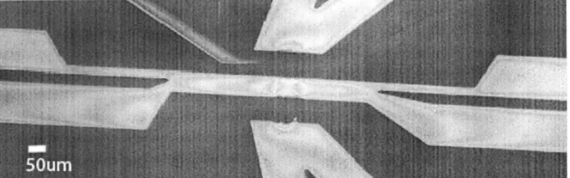
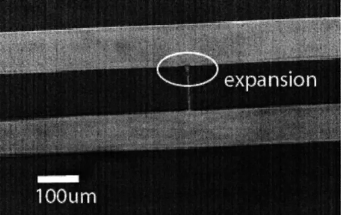
Capillary valves come in a variety of shapes and forms, including the capillary burst valve, check valve, and delay valve. As we want to retain liquid in selected areas only, we are most interested in the capillary burst valve. In a capillary burst valve, a sudden geometrical expansion of the microchannel traps the meniscus at the beginning of the expansion [29]. In our systems, this expansion is used to confine Nafion to an interconnecting channel between two sample channels (see Figure 9), and the design would need to provide for that function.
Figure 9. Two microchannels are connected by a thin 10 micron wide channel. The sudden expansion from the thin channel to the wide microchannel constitutes a capillary valve for Nafion membrane formation.
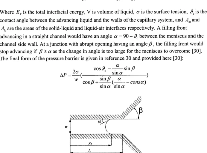
The calculations shown here assume no surface treatment on our channel surfaces, which is true for all of our devices. For the liquid to be pinned at the interface, the curvature of the liquid meniscus in a system undergoing capillary flow needs to be altered so that the filling front is stopped [30]. The capillary pressure in a rectangular channel can be estimated by calculating the interfacial energy of the liquid-gas-solid phase system [30]. Since the aspect ratio in our
![Figure 1 Various ways to use the biotin-avidin system to attach biomolecules a) Biotinylated molecule-avidin-biotinylated capture agent sandwich [19]](https://thumb-eu.123doks.com/thumbv2/123doknet/14733378.573545/17.918.306.614.122.331/figure-various-biomolecules-biotinylated-molecule-biotinylated-capture-sandwich.webp)