HAL Id: hal-02879733
https://hal.archives-ouvertes.fr/hal-02879733
Submitted on 24 Jun 2020HAL is a multi-disciplinary open access archive for the deposit and dissemination of sci-entific research documents, whether they are pub-lished or not. The documents may come from teaching and research institutions in France or abroad, or from public or private research centers.
L’archive ouverte pluridisciplinaire HAL, est destinée au dépôt et à la diffusion de documents scientifiques de niveau recherche, publiés ou non, émanant des établissements d’enseignement et de recherche français ou étrangers, des laboratoires publics ou privés.
Effect of Co-Mo catalyst preparation and CH4/H2 flow
on carbon nanotube synthesis
Egor V. Lobiak, Viktoriia R. Kuznetsova, Emmanuel Flahaut, Alexander V.
Okotrub, Lyubov G. Bulusheva
To cite this version:
Egor V. Lobiak, Viktoriia R. Kuznetsova, Emmanuel Flahaut, Alexander V. Okotrub, Lyubov G. Bulusheva. Effect of Co-Mo catalyst preparation and CH4/H2 flow on carbon nanotube synthe-sis. Fullerenes, Nanotubes and Carbon Nanostructures, Taylor & Francis, 2020, 28 (9), pp.1-9. �10.1080/1536383X.2020.1749051�. �hal-02879733�
OATAO is an open access repository that collects the work of Toulouse
researchers and makes it freely available over the web where possible
Any correspondence concerning this service should be sent
to the repository administrator: tech-oatao@listes-diff.inp-toulouse.fr
This is an author’s version published in:
http://oatao.univ-toulouse.fr/26124
To cite this version:
Lobiak, Egor V. and Kuznetsova, Viktoriia R. and Flahaut, Emmanuel
and
Okotrub, Alexander V. and Bulusheva, Lyubov G. Effect of Co-Mo catalyst
preparation and CH4/H2 flow on carbon nanotube synthesis. (2020) Fullerenes
Nanotubes and Carbon Nanostructures, 28 (9). 1-9. ISSN 1536-383X
https://doi.org/10.1080/1536383X.2020.17 49051
Effect of Co-Mo catalyst preparation and CH�H
2flow on carbon
nanotube synthesis
Egor V. Lobiaka, Viktoriia R. Kuznetsovaa,b, Emmanuel Flahautc, Alexander V. Okotruba, and Lyubov G. Bulushevaa
aNikolaev lnstitute of lnorganic Chemistry SB RAS, Novosibirsk, Russia; bNovosibirsk State Technical University, Novosibirsk, Russia; cCIRIMAT, Université de Toulouse, CNRS, INPT, UPS, UMR CNRS-UPS-INP N°SOSS, Université Toulouse 3 Paul Sabatier, Bât. CIRIMAT, Toulouse cedex 9, France
ABSTRACT
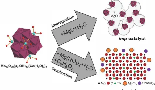
Supported Co-Mo catalysts with a given ratio of metals were prepared from polyoxomolybdate Mo12O28(µi-OH)n{Co(H2O)J4 using impregnation and combustion methods. Effects of the type of catalyst and the ratio and flow of methane and hydrogen gases on the structure of carbon nanotubes (CNTs) synthesized by catalytic chemical vapor deposition (CCVD) method were studied using transmiss ion electron microscopy and Raman spectroscopy. The catalyst prepared by combustion method yielded mainly individualized CNTs, while the CNTs were highly entangled or bundled when impregnation method was used. ln both cases, addition of hydrogen to methane led to reduction of the CNT yield. The samples synthesized using two different catalysts and the same CH.JH2 ratio and flow of gases were tested in electrochemical capacitors. A higher specific surface area of the CNTs grown over impregnation-prepared catalyst caused a better performance at scan rates from 2 to 1000 mV /s.
KEYWORDS
Carbon nanotubes; catalytic chemical vapor deposition; Co Mo catalyst; CtVH2 mixture; electrochem ical capacitors
1. Introduction
Chemical vapor deposition (CVD) is a multivariable process, where any synthesis parameter may influence the target carbon product. The key parameter in the catalytic CVD (CCVD) synthesis of carbon nanotubes (CNTs) is the composition of the catalyst. 111 Transition metals such as Fe,
Co, Ni and their alloys or with addition of Mo are common catalysts for this process. The efficiency of the catalyst for the growth of CNTs of different morphologies depends on the choice of the catalytic support, which allows controlling the size and distribution of catalytic metals. 121 The most
often used supports are graphite, quartz, magnesium oxide, zeolite, alumina, silicon, silical31 and less common substrates
such as stainless steel, microfibrous composite materials, 141
and glass mat151 have also been reported. The interaction of
the support with the active metal through van-der-Waals and electrostatic forces and/or surface groups affects the mobility and sintering of the metal161 and thus modifies its activity.111 For example, Chai et alP1 showed that the performance of CoO catalyst for the growth of CNTs from methane at 700°C decreased as follows for oxide supports: A}zO3> CeOz> zeolite > SiOz> TiOz> CaO > MgO. The use of the MgO support for a Fe/Mo catalyst provided the highest yield of single-walled CNTs (SWCNTs) from methane at 850°C as compared to other supporting materials.181
There are several methods for the preparation of sup ported catalysts and among them are sol-gel, precipitation, impregnation and combustion. The impregnation is a simple method not requiring any specific equipment, where a por ous support (MgO, CaO) is impregnated with a solution (usually aqueous) of metal salts, such as acetates,191 nitrates1101 and ammonium heptamolybdateY11 For example, the catalyst used in the well-known CoMoCat process for the synthesis of SWCNTs is prepared by impregnation of SiO2 by an aqueous solution of Co(NO3h and (NH4)6Mo,O24 followed by drying in an oven at 80 °C and calcination at 500 °C. 1121 Another common method is the combustion (fast thermal decomposition involving redox reactions) of a solution of metal salts with an organic reduc ing compound. Combustion of solutions of metal nitrates, ammonium heptamolybdate with citric acid or urea was used to produce the catalysts used for the synthesis of dou ble-walled CNTs (DWCNTs). 1131
The first stage of the preparation of bi- or three-metallic catalyst is usually dissolution of metal-containing com pounds used in the required ratio in a solvent. 111 An alterna tive way is to use compounds already containing two or more of the necessary metals. An example of such com pounds is the giant polyoxomolybdate molecule with active transition metal and molybdenum atoms in a cluster core. 1141 The first compound from this family used for the synthesis of CNTs was Keplerate, containing Fe and Mo
[HxPM012O40CfiiMonFe3-0(CH3COO)15O254(H20)9sJ.f15I
The size of this molecule is 3 nm f161 and each molecule
should on the principle produce a single metal nanoparticle for the growth of a CNT of a given structure. However, SWCNTs synthesized from methane at 900 °C exhibited a distribution of diametersY51 The goal of selectivity was
�� � using
Na15[Na3C{Co(H2O)4}6{WO(H2O)h(P2W12O48h), which
gave W 6Co7 catalysts for the synthesis of (14,4) chiral
SWCNTs with a selectivity of 97%.r171 Thus, metal-contain
ing cluster molecules can be a source of catalysts with well controlled structures for the CCVD growth of high purity CNTs possessing a specific morphology and structure.
In the first work and subsequent investigations of polyoxo
molybdate molecules for the preparation catalysts, SiOi,/Si substrates were used for deposition of molecules that resulted in very low yields of CNTs and created difficulties for their recovery by detachment from the substrate.f15•18·191 Edgar et al. for the first time distributed various Fe-containing poly
oxomolybdates on MgO and Al2O3 supports and obtained
mixtures of SWCNTs and multi-walled CNTs (MWCNTs)
from methane at a temperature of 1000 °c.f20J Sirnilar results
were achieved using the Keplerate with the Al2O3 supportf211
and MgO support.f221 Well-graphitized MWCNTs were
obtained from CiHJH2 at 900 °C using e-Keggin-type poly
oxomolybdate clusters Mo12O28û12.-OH)i2{Ni(H2Oh}4 and
Mo12O2s(µi-OH)!2{Co(H2Oh}4 on MgO supports.r23I The use
of supported polyoxomolybdates for the synthesis of CNTs is however still far from having been fully exploited
One more important parameter in the CCVD synthesis is the gaseous carbon source, which is typically methane, ethyl ene, acetylene or carbon monoxide.r6)·conversion of a reac tion gas to CNTs is always associated with the formation of various carbon by-products. Among the hydrocarbons, methane is the most thermodynarnically stable and its pyr olysis yields only carbon and hydrogen atoms. f24I Thus, methane is often mixed with hydrogen to control the forma tion of unwanted carbon species in gas phase. In this point of view, it is important to determine the role of H2 in the CNT synthesis. One of the first studies on this topic was dealing with the arc-discharge synthesis process, where CNTs free of amorphous carbon were produced, but the role of H2 was not thoroughly discussedf25I Later, decom position of CH4 in an electric arc to C2H2 and H2 was reported.f261 The influence of hydrogen was also reported for the CCVD synthesis of CNTs. Flahaut et az.r27I identified the optimal content of CH4 in mixture with H2 for the syn thesis of DWCNTs. The yield of DWCNTs increased as well as the formation of carbon nanofibers when the content of CH.i was increased from 3 to 30 mol.%. Xiong et az.rzsJ syn thesized DWCNTs on Fe-Mo/MgO catalyst when they diluted CH4 with H2. This effect of H2 was related to the slowing of the processes of decomposition, diffusion, and precipitation of carbon atoms. Biris et al.r29I showed similar
effect of H2 on the growth of SWCNTs and they proposed a decrease in the size of metal catalyst in hydrogen environ ment as the explanation. There is no doubt about a signifi cant role of hydrogen in improving the structural quality of
CNT walls, as described in the many works devoted to this effect. f30-34l
In the present work, the Mo12O28(µ2-OH)12{Co(H2Oh}4 cluster molecule with a Co4Mo12 core was chosen as a pre cursor of MgO-supported catalysts. We compared the cata lysts prepared by impregnation or combustion methods for the CCVD growth of CNTs from a mixture of CH4 and H2 and studied the effects of the composition and rate of the gas flow on the structure of the carbon product.
2. Experimental part 2.1. Materials
High purity Magnesium oxide MgO (analytical reagent qual ity), cobalt (II) acetate Co(OOCCH3h-4H2O (analytical
reagent quality, anhydrous), ammonium heptamolybdate tetra hydrate (Nfii)�o7Ü24·4H2O (>99%), acetic acid CH3COOH
(puriss.), hydrazine sulfate N2�SO4 (p.a), magnesium nitrate
Mg(NO3h·6H2O (analytical reagent quality), citric acid
C6H8O7 (analytical reagent quality), and hydrochloric acid
(puriss. spec.) were used for the synthesis of catalysts and the purification of CNTs. Methane CH.i (99,95%) and hydrogen H2 (99,9999%) were used for the growth of CNTs.
2.2. Preparation of catalysts
Mo12O2S(µ2-OHh2{Co(H2Oh}4 (briefly {Co4Mo!2}) was syn
thesized as described in the original work. f35I Shortly, Co(OOCCH3h-4H2O (11.25 g) and (NH4)6Mo7O24·4H2O
(3.36 g) were dissolved in diluted acetic acid (290 mL) and hydrazine sulfate (0.62 g) was added to the solution. Polyoxomolybdate {Co4Mo12} was precipitated after the
heating of the solution at 65 °C for three days.
The methods used for the catalyst preparation and the sche matic structure of the catalysts are illustrated in Figure 1. The preparation of catalyst by impregnation comprised the follow ing steps: an aqueous suspension of {Co4Mo12} and commercial
MgO was stirred at 80 °C until the full evaporation of water. The peach-coloured {Co4Mo!2}/MgO sample was dried in air at
80 °C for 12 h. Decomposition of {Co4Mo12} /MgO at 700 °C in
air for 10 min produced the Co-Mo/MgO catal(zst, which struc ture was already described in details earlier. 231 The catalyst prepared by impregnation method is further denoted as imp catalyst. The combustion process consisted of the following steps: {Co�od (0.2 g), Mg(NO3h 6H2O (17.7 g) and citric
acid (7.4 g) were dissolved in deionized water (600 mL) and the resultant solution was placed in a muffle furnace preheated at 550 °C and left until dryness. The catalyst prepared by combus tion method is further denoted as comb-catalyst We propose it bas a solid solution structuref361 for MgO sirnilar to the catalysts
obtained using the same proceduref37I where Co may be in sub
stitution of MgO in the MgO lattice, but this is not possible for Mo. However, during the process, O>MoO4 or MoO3 can be
formed, then it can be fixed on surface of MgO but the exact form and location of Co and Mo are unclear. Analysis by atomic emission spectroscopy revealed a content of Co ca. ~ 1 wt.% and Mo ca ~5 wt.% for both catalysts.
imp-catalyst
ooeo
•
•••••
•
••••••
O
•
··•
·
·
•
•
·
·
•
•
·
•
·
·
•
•
·
•
·
·
•
•
·
•
·•
·
·
·
•
·
·
•
•
·
o
O
···
•
·
•
·
•
·
•
·
•
·
•
·
·
•·•···
•
·
·
·
•
·
·
·
·
·
•
·
·
·•
·
•·•·•·•·•
• Mg • 0 •Co Q Mo03 ecoMo04 comb-catalystFigure 1. Illustration of impregnation and combustion methods of catalyst formation started from Mo12028{µ2 OH)u{Co(H20hl• cluster molecules.
1000°c
10 min, H2 150 ml/min
1000°c
Figure 2. CCVD profile of CNT synthesis. 2.3. Synthesis of carbon nanotubes
Room
temperature
The procedure for the CNT synthesis was the same for both
catalysts and involved three steps shown in Figure 2. A cata
lyst was distributed in a cerarnic boat, which was placed in the cold zone of a quartz tube 4.5 cm in diarneter embedded in a horizontal tubular stainless steel reactor of 1 m length.
The reactor was filled with hydrogen and heated to 1000°C.
After that, the cerarnic boat was introduced into the hot zone of the reactor. The sample was flushed with hydrogen at a fl.ow rate of 150 mUmin to activate the catalyst during 10 min. The CCVD synthesis was carried out in a gaseous mixture of hydrogen and methane with different ratios and flow rates for 30 min. Then, the reactor was flushed with hydrogen (150 mL/min) for 10 min. As a result, black pow ders were obtained.
The products were treated with a concentrated aqueous solution of HCl to dissolve the MgO support as well as ail the accessible metals. Since this acid is a non-oxidizing agent, the used purification treatment does not introduce functional groups on the CNT surfaceP81 Then CNTs were filtered and washed with distilled water until neutral pH. Finally, CNTs were dried in air at 80 °C for 12 h. In both catalysts, cobalt is the main active metal for CNT growth and CNT yields were calculated as m:;1 x 100%.
2.4. Instrumental methods
Transmission electron microscopy (TEM) images were obtained using a JEOL-2010 microscope operated at 200 kV.
Raman spectra were reco rded on a LabRAM HR Evolution HORIBA spectrometer using 514 nm Ar+ laser radiation.
CNTs were tested as working electrodes in a three electrode cell to investigate their electrochemical properties. The method of preparation of the electrodes consisted in a homogenization of a CNT sarnple (5 mg) with a 62 wt. % solution of Teflon F-4D binder in aqueous solution followed by rolling of the mixture in ethanol (a few drops) to form a filin. Platinum foil and Ag/ AgCl electrode were used as current collector and reference electrode, respectively. The platinum counter electrode and the working electrode were separated with polypropylene membrane impregnated with a 1 M H2SO4 aqueous solution. Cyclic voltammetry (CV) curves were recorded using a Biologie SP-300 instrument in a potential window from O to 1 V at scan rates from 2 to 1000 m V /s. The specific capacity of the electrodes was determined using the formula C
=
A/(V. xm), where A is the area under the positive curve, v. is the scan rate and m is the mass of carbon material.3. Results and discussion
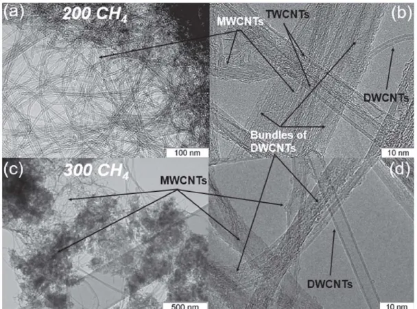
3.1. lmpregnation-pr oduced catalyst for CNT synthesis Typical TEM images of carbon materials synthesized over imp-catalyst are shown in Figure 3. Materials contained entangled and bundled CNTs free from arnorphous carbon (Figure 3). High-resolution images revealed that the bundles consisted of DWCNTs with an outer diarneter ranging from 2 to 5 nm (Figure 3d). These nanotubes were grown when the flow rate of CH4 was 200 mL/min. The agglomerates contained individualized MWCNTs and they were formed at ail used gaseous flows. The thinnest MWCNTs with an aver age outer diameter of 5 nm grew at 200 mL/min C� flow rate (Figure 3d). A decrease in the flow rate to 100 mL/min led to the synthesis of MWCNTs with an outer diameter varying from 5 to 10 nm, with an average value of 8 nm (Figure 3b). MWCNTs with significantly larger diarneters up
Bundles of
DWCNTs
Figure 3. Low resolution (a, c, e) and high resolution (b, d, f) TEM images of CNTs synthesized using imp catalyst with a flow rate of CH4 100 mUmin (a, b), 200 mUmin (c, d) and 300 (e, f).
to 30 nm were formed when the flow rate of CH4 was increased to 300 mL/min (Figure 3e and f). In this case, metallic nanopartides were observed within MWCNTs
(Figure 3e). High concentration of carbon species in the
reaction wne can promote fast growth of CNTs and capture
of catalyst with poor adhesion to the support. In previous work the formation of a mixture DWCNTs and MWCNTs was already detected using the same imp-catalyst but under a dynamic temperature profile of CCVD process.1391
Raman spectra of the synthesized carbon materials (Figure 4a) revealed the presence of the G-peak at 1580 cm 1 corresponding to the tangential vibrations of car bon atoms in the graphene plane1401 and the disorder
induced D-peak at 1350 cm 1• 1411 The ratio of the integral intensities of D- and G-peaks (I0/IG) may be used to esti
mate the disorder in sp2-hybridized carbon materials.1421 Figure 4b surnmarizes the data on CNT yield and IofIG value depending on the CHJH2 ratio and flow rate. The
lowest and highest values of Ioflc ratio were obtained for
the CNTs synthesized with 200 mL/min and 300 mUmin of C�, respectively (Figure 4a). Dilution of methane with hydrogen resulted in a lower yield of CNTs and a decrease or no change in the I0/IG value (Figure 4b). Zhan et al.
observed a similar trend for the CNT yield when the rate of CH4 flow increased with a constant H2 flow. l43l An improvement of the atomic ordering in CNT walls was reported when the CH4 flow increased. l44l In our experi
ments, a stationary state near the catalytic centers was achieved at 200 mL/min of CH4 flow. A change of the flow rate resulted in strongly non-equilibrium growth conditions and the formation of thicker and defective CNTs (Figure 3).
We can condude that 200 mL/min of C� represents an optimal synthesis condition providing a high yield of CNTs and good structural quality of their walls. When methane was diluted with hydrogen in a ratio 2: 1 and 1: 1, production of CNTs decreased due to the decrease in carbon concentra tion during the synthesis. However, improvement of the crystallinity of CNT walls in the presence of H2 was
-50CH/50H2 -100CH, -100CH/50H2 -150CH, =! -200CH, � -300CH, � tA C: a, 1200 1500 Raman shift, cm·1 G (a) 11000 (b) 9000 �
i
8000 !a. 7000.,
·;:. 6000 1-U 5000 4000 0.8 0.6 3000 ...---����---..-.-1
50/0 50/SO 100/G 100/50 15(1/0 150/50 100/100 20010 1501150200l100 30010 CH/H2, mUminFigure 4. (a) Raman spectra of CNTs obtained with imp catalyst at 100, 150 and 200mUmin total CH.JH2 flow rates. (b) Influence of ratio and gas flow rates
of CH.JH2 on CNT yield and lo/lG values (shown by bold numbers). The direction of the arrows indicates a decrease in CNT yield when CH4 was diluted with H2
(for a given total flow rate).
evidenced at 150 mL/min and 300 mL/min total flow rates of CHJH2. At other flow rates, there was no effect of H2 addition on the disorder of the CNT structure. Ohashi et al. proposed that the addition of H2 to CH4 is the necessary
condition to synthesize CNTs free from amorphous carbon and an optimum concentration of H2 in C� was about
1:1.l45l Reynolds et al.1461 obtained the highest CNT yields
when 700 sccm of C� were mixed with 200-300 sccm of H2. In our experiments, H2 performed two main roles
for CNT formation. One of them was dilution of methane that led to decreasing the CNT yield, and the other was the stabilization effect of CH4 during the decomposition which
promoted a decreasing density of defects in CNTs.
3.2. Combustion-produced catalyst for CNT synthesis
TEM study of the product obtained using the comb-catalyst
and C� with a flow rate of 200 mUmin revealed highly
dispersed thin CNTs (Figure Sa). High-resolution TEM
images evidenced the co-existence of DWCNTs, triple
walled CNTs (TWCNTs), and MWCNTs (Figure Sb). The
average outer diameter of these CNTs was 3 nm, 5 nm and 8 nm, respectively. However, MWCNTs with a larger outer diameter of ~16 nm were also observed in the sample. Note that DWCNTs were not bundled, contrary to what was obtained for the use of imp-catalyst in the synthesis
(Figure 3c and d). When the rate of C� flow was increased
to 300 mUmin, the DWCNTs formed thin bundles
(Figure Sc and d). The growth of SWCNTs, DWCNTs and
TWCNTs is typical for catalysts prepared by combustion
method.1131 An optimal composition of the catalyst, which
provides prevalence of DWCNTs in the CNT mixture is
Mgo_99(Coo.1sMoo.2s)o.0101361 and an increase in the content
of Mo leads to an increase in the number of CNT wallsP71
The 10/IG ratios determined from Raman spectra of
carbon products varied from 0.2 to 0.8 (Figure 6a). These values are smaller as compared to those found for the CNTs synthesized over imp-catalyst (Figure 4b). Figure 6b shows CNT yields depending on the ratio and gas flow rates of CHJH2. As in the previous case, the yield decreased
when methane was diluted with hydrogen. The highest CNT yield was obtained at 150 mL/min of CH4 flow rate and the
lowest yield was reached using CH4/H2 with 50/50 mUmin. The IofIG ratio was 0.5 for the former product and 0.2 for the latter one. However, the highest 10/IG ratio was observed at 300 mUmin flow rate of C�. This can be assigned to a decrease in the number of DWCNTs and an increase in the fraction of large-diameter MWCNTs (Figure Sc and d) due to deviation of the synthesis conditions from the stationary state, similarly to what was also observed with the imp-catalyst.
Rao et al.1471 reported that H2 did not affect the yield of
SWCNTs at 800°C, however, the yield increased when the
ratio of H2/C� was equal to one at 900 °C. Usually,
SWCNT synthesis does not occur without H2, which is
needed to decrease the decomposition rate of CH4 and
hence to prevent catalyst encapsulation with carbon. Our
Raman data show that the ratio and flow-rates of CHJH2
had an effect on the diameter distribution of SWCNTs and DWCNTs, with radial breathinf modes (RBMs) thatappeared from 80 to 300 cm 1. 148 Positions of RBMs are listed in Table Sl and these data indicate the formation of
both SWCNTs and DWCNTs independently on the CHJH2
ratio and flow rate. The use of C� without H2 provided
narrower distributions of CNT diameters which were espe
cially characteristic of low flow rate of CH4• We assume that
CH4 bas enough reduction ability for the formation of metal
partides with a size acceptable for the DWCNT growth.
Addition of H2 to C� increases reduction ability, which
leads to the formation of a larger number of catalytically active metal partides, but with a different size distribution. Thus, various SWCNTs and DWCNTs are produced, but the yield of CNTs is decreased due to dilution of C�. However, there are opposite examples in the literature.
Orbaek et al. l49l identified that an increase in the partial
pressure of CH4 higher than 60% in CHJH2 promoted the
carbonization of catalytic partides and decreased the effi ciency of the reduction of the catalyst.
3.3. Electrochemical properties
The obtained CNTs were tested as electrode materials in electrochemical capacitors. Performances of CNTs synthe sized using comb-catalysts are illustrated in Figure S2.
Figure 5. Low resolution (a, c) and high resolution (b, d) TEM images of DWCNTs, lWCNTs and MWCNTs synthesized using comb catalyst with CH. flow rate of 200 mUmin (a, b) and 300 ml\min (c, d).
(a) G :::1
i-·;;; C: g
-=
100 200 300 1500 Raman shift, cm·1 20000 (b) 18000 � 16000 � 14000 ,:, ai·s:.
12000 100 mUmln 1-� 10000 8000 sooo--.---..--�---,-�-,..-�--r---... 50 50/50 100 100/50 150 CH/H2, ml/min 200 300Figure 6. (a) Raman spectra of CNTs obtained using comb catalyst at different CH.{H2 ratio and flow rates. (b) CNT yields depending on ratio and gas flow rates of
CH.{H2• The direction of the arrows indicates decreasing of yields when CH. is diluted with H2• Typically, the specific capacitance of ail electrodes increased
with decreasing scan rates due to electrolyte ions having more time to diffuse into the volume of the samples. The
CNTs synthesized at lSOmL/min flow-rate of CH4 exhibited
the best performance at ail scan rates, which could be due to a large fraction of MWCNTs in this sample.
Samples obtained in the same synthesis conditions (200 mUmin of CH4) using different catalysts were selected
for a comparative analysis of their electrochemical perform ances (Figure 7). CNTs synthesized using the imp-catalyst exhibited the higher values of specific capacitance at ail used scan rates. Specific surface area (SSA) and wettability of the material have the largest impact on the capacitance at high san rates due to the lack of time for complete diffusion of electrolyte ions. The imp-catalyst produced the CNTs
40,---;:::========::;-,
35 Cl i:i: 30 of � 25 .ll! "û 20 c,srJ
15 (J !; 10 (J ft 5 -imp-catalyst --comb-catalyst 1,$ s mVJs'·'
,
..
'·'
0-'-,--�-�-�--�-�-�-�-�----r' 0 200 400 600 Scan rate, mV/s 800 1000Figure 7. Specific capacitance as a function ri scan rate ri CNTs obtained with
possessing SSA of 382m2/g, which is markedly larger than the value of 290m2/g for CNTs synthesized using the comb catalyst. At low scan rates, redox processes can provide a significant contribution to the electrochemical capacitance. The CV curves of the samples measures at a scan rate of 5 m V /s (insert in Figure 7) exhibited the peaks at ~500 m V on the charge curve and ~200mV on the discharge curve corresponding to redox processes associated with the reduc tion of Mo6+ to intermediate MoOx oxides (2.5 < x < 3).1501
A shift between the peaks on the charge curves of the sam ples can be a sign of the difference of Mo states in imp-cata lyst and comb-catalyst. The same redox reactions were observed in our previous work and their occurrence was attributed to the etching of CNT ends during the CV testsP91 It should be noted that areas of redox peaks for both samples are very similar. Thus, it is reasonable to assume that difference in specific capacitance arises from SSA of the samples. The imp-catalyst produced DWCNT bundles and MWCNTs with thin walls (Figure 3c and d). Raman spectrum of the sample synthesized using the comb
catalyst revealed many low-intensity RBM peaks (Figure 6a) corresponding to SWCNTs and/or DWCNTs. However, TEM images revealed the prevalence of MWCNTs in this sample (Figure Sb). Sorne of the MWCNTs have thick walls and this may be a reason for the smaller SSA of the sample, causing its lower capacitance.
4. Conclusions
Two types of catalysts were prepared from Mo12O28(µ2 -OH)dCo(H2Oh}4 on MgO supports by impregnation or combustion methods. The catalysts were pretreated in reducing atmosphere at 1000 °C during 10 min. CCVD syn theses of CNTs were carried out at different flow-rates of CHJH2 during 30min at 1000°C. The yield of CNTs strongly depended on the addition of hydrogen and decreased when methane was diluted by hydrogen. TEM images revealed the formation of entangled and bundled CNTs in the case of the imp-catalyst, whereas individual CNTs were obtained using the comb-catalyst. According to Raman spectroscopy data, SWCNTs and/or DWCNTs were synthesized over the latter catalyst independently on the feeding gas composition and flow rate. Moreover, the IofIG ratios indicated formation of less disordered CNTs in that case as compared to CNTs grown on the imp-catalyst. The thicker and more disordered CNTs grew on both catalysts with an increase in CH4 flow rate. An addition of hydrogen to methane enlarged the diameter distribution of SWCNTs or DWCNTs due to the formation of catalytically active metal particles of different sizes. The electrochemical per formances of CNTs obtained using two different catalysts at the same synthesis parameters were compared in 1 M H2SO4 electrolyte. The CNTs synthesized using the imp-catalyst exhibited a higher specific capacitance at ail used scan rates mainly due to the presence of thin-wall MWCNTs, provid ing a large surface area for electrolyte ion adsorption.
Acknowledgments
We are grateful to Mr. B.A. Kolesov for the Raman analysis and Mr. P. Lonchambon for the help in the combustion synthesis of catalysts.
Disclosure statement
No potential conflict of interest was reported by the author(s). Funding
The work was supported by the Russian Foundation for Basic Research (grant N!i 18 33 01053). Mrs V.R. Kuznetsova thanks grant N!i 004 HCr 19 from Novosibirsk State Technical University.
References
[l) Dupuis, A. C. The Catalyst in the CCVD of Carbon Nanotubes a Review. Prog. Mater. Sei. 2005, 50, 929 961. DOi:
10.1016/j.pmatsci.2005.04.003.
[2) Tessonnier, J. P.; Su, D. S. Recent Progress on the Growth
Mechanism of Carbon Nanotubes: A Review. ChemSusChem
2011, 4, 824 847. DOi: 10.1002/cssc.201100175.
[3) Azam, M. A.; Zulkapli, N. N.; Nawi, Z. M.; Azren, N. M. Systematic Review of Catalyst Nanoparticles Synthesized by Solution Process: Towards Efficient Carbon Nanotube Growth.
J. Sol Gel Sei. Technol. 2015, 73, 484 500. DOi: 10.1007/
sl0971 014 3600 5.
[4) Yang, Y.; Zhang, H.; Yan, Y. Synthesis of Carbon Nanotube on Stainless Steel Microfibrous Composite Comparison of Direct and Indirect Growth and Its Application in Fixed Bed m Cresol Adsorption. Chem. Eng. Res. Des. 2018, 139, 162 173. DOi: 10. 1016/j.cherd2018.09.027.
[SI Parsian, S.; Shahidi, S.; Mitjalili, M.; Ghoranneviss, M. In Situ Synthesis of Carbon Nanotubes on Glass Mat Using Thermal Chemical Vapor Deposition Method. Fullerenes, Nanotub.
Carbon Nanostruct. 2018, 26, 551 556. DOi: 10.1080/1536383X.
2018.1457650.
[6) Shah, K. A.; Tali, B. A. Synthesis of Carbon Nanotubes by Catalytic Chemical Vapour Deposition: A Review on Carbon Sources, Catalysts and Substrates. Mater. Sei. Semicond. Process
2016, 41, 67 82. DOI: 10.1016/j.mssp.2015.08.013.
[7) Chai, S. P.; Zein, S. H. S.; Mohamed, A. R. Preparation of
Carbon Nanotubes over Cobalt Containing C atalysts via
Catalytic Decomposition of Methane. Chem Phys. Lett. 2006,
426, 345 350. DOi: 10.1016/j.cplett.2006.05.026.
[8) Qingwen, L.; Hao, Y.; Yan, C.; Jin, Z.; Zhongfan, L. A Scalable CVD Synthesis of High Purity Single Walled Carbon Nanotubes with Porous MgO as Support Material. J. Mater. Chem 2002, 12, 1179 1183. DOI: 10.1039/b109763f.
[9) Triantafyllidis, K. S.; Karakoulia, S. A.; Gournis, D.; Delimitis, A.; Nalbandian, L.; Maccallini, E.; Rudolf, P. Formation of Carbon Nanotubes on Iron/Cobalt Oxides Supported on Zeolite Y: Effect of Zeolite Texturai Properties and Particle
Morphology. Microporous Mesoporous Mater. 2008, 110,
128 140. DOi: 10.1016/j.micromeso.2007.10.007.
[10) Gulino, G.; Vieira, R; Amadou, J.; Nguyen, P.; Ledoux, M. J.; Galvagno, S.; Centi, G.; Pham Huu, C. Ci,H6 as an Active Carbon Source for a Large $cale Synthesis of Carbon Nanotubes by Chemical Vapour Deposition. Appl. CataL A Gen. 2005, 279, 89 97. DOi: 10.1016/j.apcata.2004.10.ül6.
[11) Harutyunyan, A. R.; Pradhan, B. K.; Kim, U. J.; Chen, G.; Eklund, P. C. CVD Synthesis of Single Wall Carbon Nanotubes under "Soft" Conditions. Nano Lett. 2002, 2, 525 530. DOi: 10. 10 21/ nl0255101.
[12) [13) [14) [15) [16) [17) [18) [19) [20) [21) [22) [23) [24) [25) [26)
Kitiyanan, B.; Alvarez, W.; Harwell, J. H.; Resasco, D. E. Controlled Production of Single Wall Carbon Nanotubes by Catalytic Decomposition of CO on Bimetallic Co Mo Catalysts. Chem Phys. Lett. 2000, 317, 497 503. DOI: 10.1016/$0009 2614(99)01379 2.
Flahaut, E.; Laurent, C.; Peigney, A. Catalytic CVD Synthesis of Double and Triple Walled Carbon Nanotubes by the Control of the Catalyst Preparation. Carbon 2005, 43, 375 383. DOi: 10. 1016/j.carbon.2004.09.021.
Müller, A; Krickemeyer, E.; Bôgge, H.; Schmidtmann, M.; Peters, F. Organizational Forms of Malter: An Inorganic Super Fullerene and Keplerate Based on Molybdenum Ox:ide. Angew.
Chemie Int. Ed. 1998, 37, 3359 3363. DOi: l0.1002/(SICI)l521
3773(19981231)37:24 < 3359::AID ANIE3359 > 3.0.CO;2 J.
An, L.; Owens, J. M.; McNeil, L. E.; Liu, J. Synthesis of Nearly Uniform Single Walled Carbon Nanotubes Using Identical Meta) Cont aining Molecular Nanoclusters as Catalysts. J. Am.
Chem Soc. 2002, 124, 13688 13689. DOi: l0.1021/ja0274958. Müller, A.; Sarkar, S.; Shah, S. Q. N.; Bôgge, H.; Schmidtmann, M.; Sarkar, S.; Kôgerler, P.; Hauptfleisch, B.; Trautwein, A. X.; Schünemann, V. Archimedean Synthesis and Magic Numbers:
"Sizing" Giant Molybdenum Oxide Based Molecular Spheres of the Keplerate Type. Angew. Chem Int. Ed. 1999, 38,
3238 3241. DOi: l0.1002/(SICI)l521
3773(19991102)38:21 < 3238::AID ANIE3238 > 3.0.CO;2 6.
Yang, F.; Wang, X.; Si, J.; Zhao, X.; Qi, K.; Jin, C.; Zhang, Z.; Li, M.; Zhang, D.; Yang, J.; et al. Water Assisted Preparation of High Purity Semiconducting (14,4) Carbon Nanotubes. ACS Nano 2017, Il, 186 193. DOi: l0.l021/acsnano.6b06890. Huang, S.; Fu, Q.; An, L.; Liu, J. Growth of Aligned SWNT Arrays from Water Soluble Molecular Clusters for Nanotube Device Fabrication. Phys. Chem. Chem Phys. 2004, 6, 1077. DOI: 10.l039/b315892f.
Anderson, R. E.; Colorado, R; Crouse, C.; Ogrin, D.; Maruyama, B.; Pender, M. J.; Edwards, C. L.; Whitsitt, E.; Moore, V. C.; Koveal, D.; et al. A Study of the Formation, Purification and Application as a SWNT Growth Catalyst of
the Nanocluster
[HxPM012O40CH4Mo12Fe30(O2CMe)15�4(H2O)9s)- Dalton Trans. 2006, (25), 3097 3107. DOi: 10.1039/B518395B. Edgar, K.; Spencer, J. L. The Synthesis of Carbon Nanotubes from Millier Clusters. Curr. AppL Phys. 2006, 6, 419 421. DOi:
10.1016/j.cap.2005.l 1.032.
Goss, K.; Kamra, A.; Spudat, C.; Meyer, C.; Kôgerler, P.; Schneider, C. M. CVD Growth of Carbon Nanotubes Using Molecular Nanoclusters as Catalyst. Phys. Status Solidi B. 2009,
246, 2494 2497. DOi: 10.1002/pssb.200982320.
Lobiak, E. V.; Shlyakhova, E. V.; Gusel'nikov, A V.; Plyusnin, P. E.; Shubin, Y. V.; Okotrub, A. V.; Bulusheva, L. G. Carbon Nanotube Synthesis Using Fe Mo/MgO Catalyst with Different Ratios of CH4 and H2 Gases. Phys. Status Solidi B 2018, 255, 1700274. DOi: 10.l002/pssb201700274.
Lobiak, E. V.; Shlyakhova, E. V.; Bulusheva, L. G.; Plyusnin, P. E.; Shubin, Y. V.; Okotrub, A V. Ni Mo and Co Mo Alloy Nanoparticles for Catalytic Chemical Vapor Deposition Synthesis of Carbon Nanotubes. J. Alloys Compd. 2015, 621,
351 356. DOI: l0.l016/j.jallcom2014.09.220.
Jourdain, V.; Bichara, C. Current Understanding of the Growth of Carbon Nanotubes in Catalytic Chemical Vapour Deposition.
Carbon 2013, 58, 2 39. DOI: 10.1016/j.carbon.2013.02.046. Wang, X. K.; Lin, X. W.; Mesleh, M.; Jarrold, M. F.; Dravid, V. P.; Ketterson, J. B.; Chang, R. P. H. The Effect of Hydrogen on the Formation of Carbon Nanotubes and Fullerenes. J. Mater. Res. 1995, 10, 1977 1983. DOi: 10.1557/JMR.1995.1977. Zhao, X.; Ohkohchi, M.; Wang, M.; Iijima, S.; Ichihas hi, T.; Ando, Y. Preparation of High Grade Carbon Nanotubes by Hydrogen Arc Discharge. Carbon 1997, 35, 775 781. DOi: 10. 1016/$0008 6223(97)00033 X. [27) [28) [29) [30) [31) [32) [33) [34) [35) [36) [37) [38) [39) [40) [41) [42)
Flahaut, E.; Peigney, A.; Laurent, C. Double Walled Carbon Nanotubes in Composite Powders. J. Nanosci. NanotechnoL
2003, 3, 151 158. DOI: 10.1166/jnn.2003.177.
Xiong, G. Y.; Suda, Y.; Wang, D. Z.; Huang, J. Y.; Ren, Z. F. Effect of Temperature, Pressure, and Gas Ratio of Methane to Hydrogen on the Synthesis of Double Walled Carbon Nanotubes by Chemical Vapour Deposition. Nanotechnology 2005, 16, 532 535. DOI: 10.1088/0957 4484/16/4/033.
Biris, A R.; Li, Z.; Dervishi, E.; Lupu, D.; Xu, Y.; Saini, V.; Watanabe, F.; Biris, A S. Effect of Hydrogen on the Growth and Morphology of Single Wall Carbon Nanotubes Synthesized on a FeMo/MgO Catalytic System Phys. Lett. A. 2008, 372, 3051 3057. DOi: 10.1016/j.physleta.2008.01.023.
Sharma, A. K.; Sharma, R; Chaudhary, U. Hydrogen Acetylene Gas Ratio and Catalyst Thickness Effect on the Growth of Uniform Layer of Carbon Nanotubes. Fullerenes, Nanotub. Carbon Nanostruct. 2017, 25, 397 403. DOi: l0.l080/1536383X. 2017.1320545.
Castro, C.; Pinault, M.; Porterat, D.; Reynaud, C.; Mayne L'Hermite, M. The Role of Hydrogen in the Aerosol Assis ted Chemical Vapor Deposition Process in Producing Thin and Densely Packed Vertically Aligned Carbon Nanotubes. Carbon 2013, 61, 585 594. DOi: 10.1016/j.carbon.2013.05.040.
Behr, M. J.; Gaulding, E. A; Mkhoyan, K. A.; Aydil, E. S. Effect of Hydrogen on Catalyst Nanoparticles in Carbon Nanotube Growth. J. AppL Phys. 2010, 108, 53303. DOi: 10.1063/1. 3467971.
Chinthaginjala, J. K.; Lefferts, L. Influence of Hydrogen on the Formation of a Thin Layer of Carbon Nanofibers on Ni Foam.
Carbon 2009, 47, 3175 3183. DOi: l0.1016/j.carbon2009.07.
025.
Zhang, H.; Cao, G.; Wang, Z.; Yang, Y.; Shi, Z.; Gu, Z. Influence of Ethylene and Hydrogen Flow Rates on the Wall Number, Crystallinity, and Length of Millimeter Long Carbon Nanotube Array. J. Phys. Chem C 2008, 112, 12706 12709.
DOI: l0.l021/jp802998v.
Millier, A; Beugholt, C.; Kôgerler, P.; Bôgge, H.; Bud'ko, S.; Luban, M. [Mov12030
ù'2
OH)i0H2{Ni11(H2Oh}4], a Highly Symmetrical e Keggin Unit Capped with Four Nin Centers:Synthesis and Magnetism. Inorg. Chem 2000, 39, 5176 5177. DOI: l0.l021/ic0005285.
Flahaut, E.; Bacsa, R.; Peigney, A.; Laurent, C. Gram $cale CCVD Synthesis of Double Walled Carbon Nanotubes. Chem
Commun. 2003, (12), 1442. DOi: 10.l039/b301514a.
Flahaut, E.; Peigney, A.; Bacsa, W. S.; Bacsa, R. R.; Laurent, C. CCVD Synthesis of Carbon Nanotubes from (Mg,Co,Mo)O Catalysts: Influence of the Proportions of Cobalt and Molybdenum. J. Mater. Chem 2004, 14, 646. DOI: 10.1039/ b312367g.
Lavskaya, Y. V.; Bulusheva, L. G.; Okotrub, A. V.; Yudanov, N. F.; Vyalikh, D. V.; Fonseca, A. Comparative Study of Fluorinated Single and Few Wall Carbon Nanotubes by X Ray Photoelectron and X Ray Absorption Spectroscopy. Carbon 2009, 47, 1629 1636. DOI: 10.1016/j.carbon.2009.01.046.
Lobiak, E. V.; Bulusheva, L. G.; Galitsky, A. A.; Smirnov, D. A; Flahaut, E.; Okotrub, A. V. Structure and Electrochemical Properties of Carbon Nanotubes Synthesized with Catalysts Obtained by Decomposition of Co, Ni, and Fe Polyoxomolybdates Supported by MgO. J. Struct. Chem. 2018,
59, 786 792. DOi: 10.1134/S0022476618040066.
Choi, Y. C.; Min, K. I.; Jeong, M. S. Novel Method of Evaluating the Purity of Multiwall Carbon Nanotubes Using Raman Spectroscopy. J. Nanomater. 2013, 2013, l 6. DOi : 10. 1155/2013/615915.
Dresselhaus, M. S.; Jorio, A; Souza Filho, A G.; Saito, R Defect Characterization in Graphene and Carbon Nanotubes Using Raman Spectroscopy. Proc. R Soc. A. 2010, 368, 5355 5377. DOi: 10.1098/rsta.2010.ü213.
Antunes, E. F.; Lobo, A. O.; Coral, E. J.; Trava Airoldi, V. J. Influence of Diameter in the Raman Spectra of Aligned Multi
[43)
[44)
[45)
[46)
Walled Carbon Nanotubes. Carbon 2007, 45, 913 921. DOi: 10. 1016/j .carbon.2007.01.003.
Zhan, S.; Tian, Y.; Cui, Y.; Wu, H.; Wang, Y.; Ye, S.; Chen, Y. Effect of Process Conditions on the Synthesis of Carbon Nanotubes by Catalytic Decomposition of Methane. China Particuol. 2007, 5, 213 219. DOi: 10.1016/j.cpart.2007.ü3.004. Chai, S. P.; Seah, C. M.; Mohamed, A. R. A Parametric Study of Methane Decomposition into Carbon Nanotubes over 8Co 2Mo/A1203 Catalyst. J. Nat. Gas Chem 2011, 20, 84 89. DOi: 10.1016/Sl003 9953(10)60151 X.
Ohashi, F.; Chen, G. Y.; Stolojan, V.; Silva, S. R. P. The Role of the Gas Species on the Formation of Carbon Nanotubes during Thermal Chemical Vapour Deposition. NanotechnoL 2008, 19, 445605. DOi: 10.1088/0957 4484/19/44/445605.
Reynolds, C.; Duong, B.; Seraphin, S. Effects of Hydrogen Flow Rate on Carbon Nanotube G rowth. J. Undergrad. Res. Phys.
2010, 23, 1 11.
[47)
[48)
[49)
[SOI
Rao, F. B.; Li, T.; Wang, Y. L. Effect of Hydrogen on the Growth of Single W alled Carbon Nanotubes by Thermal Chemical Vapor Deposition. Phys. E Low Dimensiona/ Syst.
Nanostruct. 2008, 40, 779 784. DOi: 10.1016/j.physe2007.09.
185.
Dres selhaus, M. S.; Dresselhaus, G.; Saito, R; Jorio, A. Raman Spect roscopy of Carbon Nanotubes. Phys. Rep. 2005, 409, 47 99. DOi: 10.1016/j.phys rep.2004.10.006.
Orbaek, A. W.; Owens, A. C.; Barron, A. R lncreasing the Efficiency of Single W alled Carbon Nanotube Amplification by Fe Co Catalysts through the Optimization of CH.JH2 Partial Pressures. Nano Lett. 2011, Il, 2871 2874. DOi: 10.1021/ nl201315j.
Martinez Huerta, M. V.; Rodrfguez, J. L.; Tsiouvaras, N.; Pena, M. A.; Fie rro, J. L. G.; Pastor, E.; Novel Synthesis Method of C O Tolerant PtRu MoOx Nanoparticles: Structural Characteristics and Performance for Methanol Elect roox:idation.
Supplemental file
Effect of Co-Mo catalyst preparation and CH4/H2 flow on carbon
nanotube synthesis
Lobiak E.V.
1,
Kuznetsova V.R.
1,2,
Flahaut E.
3, Okotrub A.V.
1,
Bulusheva L.G.
11
Nikolaev Institute of Inorganic Chemistry SB RAS, Novosibirsk, Russia
2
Novosibirsk State Technical University, Novosibirsk, Russia
3