MASSACHUSETTS INSTITUTE OF TECHNOLOGY
The RESEARCH LABORATORY of ELECTRONICS
Computer Haptics: Rendering Techniques
for Force-Feedback in
Virtual Environments
By: Chih-Hao Ho
and Dr. Mandayam A. Srinivasan
RLE Technical Report No. 639
Computer Haptics: Rendering Techniques for
Force-Feedback in Virtual Environments
By: Chih-Hao Ho
and Dr. Mandayam A. Srinivasan
RLE Technical Report No. 639
Computer Haptics: Rendering Techniques for
Force-Feedback in Virtual Environments
By
Chih-Hao Ho
M.S. Mechanical Engineering
Massachusetts Institute of Technology, 1996
SUBMITTED TO THE
DEPARTMENT OF MECHANICAL ENGINEERING
IN PARTICAL FULFILLMENT OF THE REQUIREMENTS
FOR THE DEGREE OF
DOCTOR OF PHILOISOPHY IN MECHANICAL ENGINEERING
AT THE
MASSACHUSETTS INSTITUTE OF TECHNOLOGY
FEBRUARY 2000
( 2000 Massachusetts Institute of Technology. All rights reserved.
Author
Department of Mechanical Engineering
December 17, 1999
Certified by
Dr. Mandayam A. Srinivasan v
Thesis Supervisor, Department of Mechanical Engineering
Accepted by
Professor Ain A. Sonin
Chairman, Department Committee on Graduate Students
Computer Haptics: Rendering Techniques for
Force-Feedback in Virtual Environments
By
Chih-Hao Ho
Submitted to the Department of Mechanical Engineering on December 17, 1999, in Partial Fulfillment
of the Requirements for the Degree of Doctor of Philosophy in Mechanical Engineering
Abstract
Haptic virtual environments (VEs) are computer-generated environments within which human users can touch, feel, and manipulate virtual objects in real time through force or tactile feedback. Integration of force-feedback into VEs with graphical and auditory displays is expected to have many applications in the area of medical training, CAD/CAM, entertainment, graphic arts, and education. The development of force-feedback system for VEs is in the research area of haptics, which can be divided into three sub-categories: human haptics, machine haptics, and computer haptics. Human haptics focuses on the understanding of human hand brain system. Machine haptics focuses on the design and development of force-feedback devices (also called haptic interfaces). Computer haptics focuses on the algorithm and software for the creation of virtual objects and how to efficiently display these objects to the users.
The research of this thesis focuses on computer haptics. First, a point-based interaction paradigm called Neighborhood Watch is developed to allow human users to use a point probe to manually explore and manipulate virtual objects. A major feature of
Neighborhood Watch is that the computational time is independent of the number of
polygons of the virtual objects. Second, another interaction paradigm, called ray-based
rendering, which allows human users to use a line probe to interact with virtual objects is
also described. The computational time with ray-based rendering is also essentially independent of the number of polygons of the virtual objects. In addition to the two haptic interaction paradigms, various object property display algorithms have also been developed. Using these algorithms, we can add friction and textures to the surfaces of arbitrarily shaped virtual objects and also add compliant and dynamic behavior to the virtual objects. All of the techniques developed for haptic rendering were finally incorporated into a surgical simulator to demonstrate their usefulness.
Thesis Supervisor: Mandayam A. Srinivasan
Title: Principal Research Scientist, Department of Mechanical Engineering Thesis Committee: Harry H. Asada
Title: Professor, Department of Mechanical Engineering Thesis Committee: David C. Gossard
Contents
1. Introduction- --- --- --- --- --- --- 6
2. Background--- --- 10
2.1 Force-feedback Devices - - - 10
2.2 Rendering Algorithms - 14 3. Hardware Set-up and Software Architecture - - - 24
3.1. Hardware Set-up - - - 24
3.1.1. Haptic Interface for Point-Based Interaction - - - 24
3.1.2. Haptic Interface for Ray-Based Interaction - - - 25
3.2. Software Architecture - - - 26 4. Point-based Interaction - - - 28 4.1. Introduction --- --- 28 4.2. Hierarchical Database--- --- ---- 31 4.3. Collision Detection - - - -- - - 33 4.4. Collision Response - - - 39 4.5. Results-- - --- 40 5. Ray-Based Interaction--- 43 5.1. Introduction --- 47 5.2. Hierarchical Database --- --- 50 5.3. Collision Detection - - - 53 5.4. Collision Response - - - 60
5.5. An Experiment on the Haptic Perception of 3D Objects: Ray-based versus Point-based Interactions - - - 65
5.6. Conclusions - - - 66
6. Haptic Display of Object Properties - - - 69
6.1. Force Shading - - - 70
6.2. Friction--- - --- --- 73
6.3. Texture--- --- - 75
6.3.1. Magnitude of Force - - - 75
6.3.2. Direction of Force - - - 77
6.3.3. Height Field of Textures - - - 79
6.4. Dynamics--- 82
6.5. Compliance--- 83
6.6. Conclusions --- --- --- - 86
7. Application - Simulation of a Medical Process - - - 87
7.1. Introduction--- --- 87
7.3. The Need for a Training System - - - 93
7.4. Selection of a Laparoscopic Procedure for Simulation - - - 94
7.5. Hardware Setup - - - 96
7.6. Software Setup - - - 99
7.6.1. Geometric Data on Human Organs - - - 100
7.6.2. Modeling of Surgical Instruments - - - 101
7.6.3. Collision Detection - - - 103
7.7. Material Modeling--- 108
7.8. Results--- - --- --- 112
8. Suggestions for Future Work - - - 115
Appendix--- 118
Chapter 1
Introduction
Virtual environments (VEs) are computer-generated environments with which a human user can interact in real time. In particular, a multi-modal virtual reality (VR) system will enable the humans to interact with the computer and obtain visual, auditory, and haptic sensations, as they would encounter in real life. A VE system typically consists of several interface devices such as a head mounted display and a position tracker that send and receive signals of the interactions between the computer and a human user. The development of VEs is a very popular research topic for the past decades. The techniques in creating visual and auditory VEs have already been broadly applied to entertainment such as the creation of video games and movies. In addition to the visual and auditory VEs, the development of haptic VEs that can provide human users with force-feedback interaction is a relatively new research topic in the area of virtual reality simulation. With the addition of force-feedback interaction to the VEs, the users will be able to touch, feel, and manipulate virtual objects in addition to see and hear them. The haptic VEs, with the feature of force feedback, are particularly helpful when manual actions such as exploration and manipulation are essential in an application. For example, surgical residents would benefit from training in a haptic VE as it offers a consistent environment and unlimited opportunity to practice surgical procedures. Aside from medical training, other applications of the haptic VEs may include CAD/CAM, entertainment, graphic arts, and education.
In creating haptic VEs, a device called " haptic interface" is used to provide force-feedback interactions via "haptic rendering" techniques. The typical functions of a haptic interface are to sense the position of the user's hand and reflect forces back to the user. The term "haptic rendering" refers to the process that compares the position information of user's hand with the data of virtual objects and calculates an appropriate interaction force to send back to the user. A computer is the main hardware that performs the haptic rendering. For a given position information, a computer checks whether the hand is inside the virtual objects or not. If the hand is inside the virtual objects, it sends force commands to the haptic interface to prevent the hand from further penetrating into the objects. It should be noted that, with the technology available today, the user unfortunately couldn't get the complete sensation of touching the virtual objects directly as in real life. The user can touch and manipulate objects in virtual environments only through an end-effector of a haptic device (see Figure 1-1). This end-effector could be a thimble in which the fingertip could be inserted, a stylus or a mechanical tool that could be held in the hand, or an actuated glove or exoskeleton that the user could wear. During the simulations, the user manipulates the end-effector and feels the reaction forces when the end-effector contacts the virtual objects. Although the end-effector can have different physical shapes and designs, they can be modeled as a point, a line, or a 3D object in virtual environments for simulating haptic interactions.
Most of the techniques for creating visual VEs are covered in the research area of computer graphics, which is mainly concerned with the generation and rendering of graphic images. Some of the techniques in creating haptic VEs are similar to those in computer graphics. However, there are still many differences between them. To differentiate the difference between the techniques in creating visual and haptic VEs, researchers have proposed the term "Computer Haptics" to represent the field of research that is concerned with the generation and rendering of haptic virtual objects (Srinivasan and Basdogan, 1997 and Ho, Basdogan, and Srinivasan, 1999).
A
ndeffo
Ha
i
It
x,
= ...
.,
T
\,,.
Haptic Interface Virtual Object
(a) (b)
Figure 1-1. The concept about a human user interacting with virtual objects: (a) The user
puts the index finger into the end-effector of the haptic interface. When the user moves the index finger, the end-effector will follow the movement, too. (b) The computer reads the position information of the effector and uses a model to represent the end-effector. In this example, the model of the end-effector is simplified to a point. The computer then checks whether the point has a collision with the virtual object or not. If there is no collision, the computer will not send any force to the haptic interface. However, if the point penetrates the object, the computer will send forces to the haptic interface to prevent the end-effector from further penetrating into the object.
Haptic display of 3D objects in virtual environments, with various applications in many areas, has been an exciting and challenging research topic for scientists and engineers in the last few years (Srinivasan, 1995, Burdea, 1996, Srinivasan and Basdogan, 1997, Salisbury et al, 1995, and Salisbury and Srinivasan, 1997). It is generally accepted that for haptic objects in VEs to appear natural, the haptic servo rate should be of the order of 1000 Hz. In other words, the computational time for each haptic servo loop (where a reaction force is computed for one position input) should take about a millisecond or less. If the 3D objects in VEs are simple primitives (e.g. cube, cone, cylinder, sphere, etc.),
End-effector Haptic Interface Point
this goal could be easily achieved with the computer technology available today. However, realistic synthetic environments usually contain multiple 3D objects that have complex surface as well as material properties. Therefore, the development of efficient haptic interaction techniques that can render arbitrary 3D objects in a time-critical manner becomes essential.
The research of this thesis focuses on two fundamental fields of computer haptics. The first one is a haptic interaction paradigm that defines the nature of the "haptic cursor" and its interaction with object surfaces. The second one is an object property display
algorithm that renders surface and material properties of objects. Finally, various
techniques developed in this research were incorporated into a surgical simulator to demonstrate the usefulness of these techniques.
A literature review is first described in the next chapter to give an overview about computer haptics. The hardware and the software architecture for creating haptic VEs are described in chapter 3. After that, I describe a point-based haptic interaction paradigm in chapter 4. By using the point-based rendering technique, we can create VEs that allow users to use a point probe to interact with arbitrary 3D polyhedral objects. The second haptic interaction paradigm that is called ray-based rendering technique is presented in chapter 5. The ray-based rendering techniques allow users to use a line probe to interact with virtual objects. In chapter 6, I present various object property display algorithms. These techniques could add different material properties to the virtual objects. The details of the surgical simulator developed in this research are described in chapter 7. The suggestions of future work are summarized in chapter 8.
Chapter 2
Background
2.1 Force-Feedback Devices
In haptic VEs, the typical functions of a force-feedback haptic interface are to sense the position of the user's hand and reflect forces back to the user. In the past few years, different types of haptic interfaces have been developed for different purposes. An important distinction among haptic interfaces is whether they are tactile displays or net force displays. The corresponding difference in interactions with VEs is whether the direct touch and feel of objects contacting the skin is simulated or the interactions are felt through a tool. Simulation of interactions through a tool, such as feeling the virtual world through a rigid stick, requires only net force (and torque) display. Simulation of direct contact with objects is much more difficult since it requires a tactile display capable of distributing the net forces and torque appropriately over the region of contact between the object and the skin (see Ikei, Wakamatsu, and Fukuda, 1997 for a recent example of such devices). Since human tactile sensation is very complex and delicate, the performance of the currently available tactile displays is inadequate in comparison to the human sensory
capabilities.
At present, net-force display devices that can match at least some of the capabilities of the human haptic system are available. Depending on how the interfaces are set up, they can be categorized as ground-based or body-based. The ground-based interface has devices attached to a fixed object. Whereas, the body-based interface is a freestanding device attached directly to human hands. Since the body-based devices usually provide
larger workspaces, they require more complex calculation in rendering. Current available software technologies don't provide good enough support for such computation. In addition, human hand is a very versatile organ, the body-based devices developed today provides only a limited simulation. Therefore, general speaking, ground-based devices provide better performance in the creation of haptic VEs than the one simulated by body-based devices.
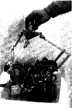
The following figures are examples of force-feedback haptic interfaces. The devices shown in Figure 2-1 to 2-6 are all capable of sending ground-based net force to the users through an end-effector. They could be used to simulate indirect contact. The algorithms developed in this research are for this type of haptic interfaces. The devices shown in Figure 2-7 and 2-8 are force-feedback gloves. These gloves are body-based devices. These devices could usually provide larger workspace compared to those shown in Figure 2-1 to 2-6. More haptic devices and the developing history of haptic interfaces could be found in Minsky, 1995 and Burdea, 1996.
I
4
/
Figure 2-1. The "PHANToM" by SensAble Technology, Inc.
Figure 2-2. 3 DOF "Linear Haptic Display" by haptic technologies Inc.
Figure 2-3. "Freedom-7" Haptic Device by Vincent Hayward at McGill University.
Figure 2-4. "Haptic Master" by Iwata at University of Tsukuba.
Figure 2-7. "RM II" Force Feedback Device developed in Rutgers University.
Figure 2-8. "CyberGrasp" by Virtual Technologies, Inc.
2.2 Rendering Algorithms
The goal of haptic rendering is to display the haptic attributes of surface and material properties of virtual objects in real time via a haptic interface device. As mentioned earlier, the user can touch and manipulate virtual objects only through an end-effector of a haptic device. This end-effector could be a thimble, a stylus, a mechanical tool, or an actuated glove. Since the users use the end-effector to explore the virtual environments, we use the general term "probe" to represent these end-effectors. In order to detect the collisions between the probe and the virtual objects, we have to create a mathematical
model in the VEs to represent the probe. Although the probes can have different physical shapes and designs, they can be modeled as a point, a line, or a 3D object in virtual environments for simulating haptic interactions.
In order to help readers understand the process of haptic rendering, I give a simple example here. The probe is modeled as a point in this example. The virtual object we are going to create is a sphere (see Figure 2-9). The radius of the sphere is R and its center is located in C whose coordinate is (Cx, Cy, Cz). In each servo loop, we can get the location of the probe from the sensors of the haptic interface. Let's say we read the sensors and find that the probe is located at position P whose coordinate is (Px, Py, Pz) for the current loop. Next step is to do collision detection to see whether the probe is inside the sphere or not. To do this, we calculate the distance D between the probe and the center, which will be the square root of ((Cx-Px)*( Cx-Px)+( Cy-Py)*( Cy-Py)+( Cz-Pz)*( Cz-Pz)). If D is larger than R, we know that the probe is outside the sphere. On the other side, if D is smaller than R, the probe is inside the sphere and, therefore, we need a collision-response phase to calculate the interaction force. To decide the force, we need to find out the penetration first. The penetration direction V will be from the probe pointing to the center: (Cx-Px, Cy-Py, Cz-Pz). We normalize the vector V to make it a unit vector. After that, we can calculate the penetration vector PV, which is equal to
(R-D)*V. To calculate the interaction force, we use a simple mechanistic model F =-k,
where X is the penetration vector and k is the spring constant representing the material stiffness. So, the force that will be sent to the user will be (-k * PV). In each servo loop, the haptic rendering basically repeats the same procedure to compute the interaction force.
P0
-aP
Figure 2-9. The procedure of haptic rendering between a point probe and a virtual
spherical object. The center of the spherical object is located in C and its radius is R. At time to, the point probe is located at PO and, at time t, it moves to PI. At time to, the distance between the PO and C is larger than R. Therefore, the point probe is outside the spherical object. At time t, the distance between the PI and C is smaller than R, which means that the point probe is inside the spherical object. We can calculate and find out that the penetration is the vector PV. By using a simple mechanistic model, we send a force (-k * PV) to the user to prevent the point probe from further penetrating into the object.
Initial haptic rendering methods modeled the probe as a single point since it is computationally less expensive. In this haptic interaction model, the user could interact with 3D objects in VEs through the end point of the haptic device, which is defined as the Haptic Interface Point (HIP). Massie and Salisbury (1994) developed the PHANToM haptic interface device and proposed a simple method to render 3D geometrical primitives. Later, Zilles and Salisbury (1995) developed a more sophisticated, constraint-based method to render polyhedral objects. They defined a "god-object" point, to represent the location of a point that is constrained to stay on a particular facet of the
object when the HIP penetrates that object. Lagrange multipliers are used to compute the new location of the god-object point such that the distance between the god-object and the haptic interface point is minimized. Adachi, Kumano, and Ogino (1995) and Mark et al. (1996) suggested an intermediate representation (a tangent plane) to render virtual surfaces. Although the forces are updated frequently (-1 kHz), the tangent plane is updated more slowly. Ruspini, Kolarov, and Khatib (1997) proposed an approach similar to the god-object technique and improved the collision detection algorithm by constructing a bounding sphere hierarchy and configuration space. Gregroy et al. (1999) proposed a framework for fast and accurate collision detection by combining many of the techniques in computer graphics. Ho, Basdogan, Srinivasan (1999) have also proposed a rendering method called "Neighborhood Watch" to render polyhedral objects. The local connectivity information is used to reduce the computation and make the computational time independent of the number of polygons of the objects in the VEs. In addition to the techniques that render polyhedral objects, Avila and Sobierajski (1996) proposed techniques to render 3D volumetric objects. Salisbury and Tarr (1997) proposed a method to render implicit surfaces. Thompson, Johnson, and Cohen (1997) proposed a method for rendering NURBS surfaces. Since the probe is modeled as a point for these methods, I call them point-based haptic rendering.
In a departure from the point-based methods described above, we have proposed a
ray-based interaction technique where the probe is modeled as a line segment rather than a
point (Ho, Basdogan, and Srinivasan, 1997 and Basdogan, Ho, and Srinivasan, 1997). Using ray-based interaction technique, we can simulate the contact between the tip as well as side of the probe with several convex objects at the same time. We can then compute the associated forces and torques to be displayed to the user.
One further step for improving haptic interaction paradigm might be to model the probe as a 3D object. However, the detection of collision between the 3D probe and 3D objects is computational too expensive for haptic rendering since the required update rate is
about 1000 Hz. Instead of directly detecting collision between 3D probe and 3D objects, researchers have proposed alternative methods to approach this goal. For example, McNeely, Puterbaugh, and Troy (1999) have presented a voxel-based approach. In their approach, static objects in the scene are divided into voxels and the probe is modeled as a set of surface points. Then multiple collisions are detected between the surface points of the probe and the voxels of the static object. The calculation of interacting forces is based on a tangent-plane force model. A tangent plane whose normal is along the direction of the collided surface point is constructed at the center of each collided voxel. Then, the net force and torque acting on the probing object is obtained by summing up all of the force/torque contributions from such point-voxel intersections. Although this approach enables 3D probe to interact with static rigid objects, its extension to dynamical and deformable objects would significantly reduce the haptic update rate because of the computational load. Moreover, rendering of thin or small objects will also have problems with this approach.
In addition to the interaction paradigms described above, various techniques have been proposed for displaying surface properties such as shape, friction, and texture of virtual objects. Most of these techniques are developed for polyhedral objects. One of the advantages for polyhedral representation of 3D objects is that any type of objects can be represented in polyhedral format within an arbitrary tolerance. However, due to the sensitive perception of our haptic system, the users can easily feel the discontinuity at the connection of two faces that may be undesirable for some applications. To solve this problem, Morgenbesser and Srinivasan (1996) have proposed force-shading methods to smooth the feel of polyhedral objects by eliminating the force discontinuities at polygonal boundaries. In addition to smooth the object surfaces, researchers have also proposed techniques to add roughness to the surfaces. Salcudean and Vlaar (1994), Salisbury et al. (1995), Chen et al. (1997) and Green and Salisbury (1997) have proposed different techniques to simulate friction on smooth surfaces. Minsky et al. (1990 and 1995)
proposed algorithms to simulate textures on 2D surfaces. Siira and Pai (1996) and Fritz and Barner (1996) have also proposed methods to generate stochastic textures on well-defined surfaces. Basdogan, Ho, and Srinivasan (1997) presented techniques to add haptic textures to arbitrary 3D polyhedral objects.
Some readers may think that the interaction paradigms for computer haptics are identical to those collision detection and collision response techniques in computer graphics. Indeed, many of the techniques in these two areas are identical. However, the basic concept is different between the two research areas. The main difference is that the program can fully control the behavior of the objects in graphic VEs, not in haptic VEs. For example, in graphic VEs, when an object moves toward another object and, finally, a collision occurs (Figure 2-10), the program could send forces to the two collided objects and change their velocity to make the two objects separated. Since the program can control the behavior of the objects, the overlap between the two objects usually occurs only in a small amount of time. Therefore, it is usually good enough for the collision response algorithms to make decision based on objects' current positions.
(a) (b)
Figure 2-10. A simulation of dynamic behavior in computer graphics. (a) One object
moves toward another object. (b) The moving object contacts the other object. The collision detection algorithm could detect the overlap between the two objects. The collision response algorithm is then used to change the velocity of the two objects.
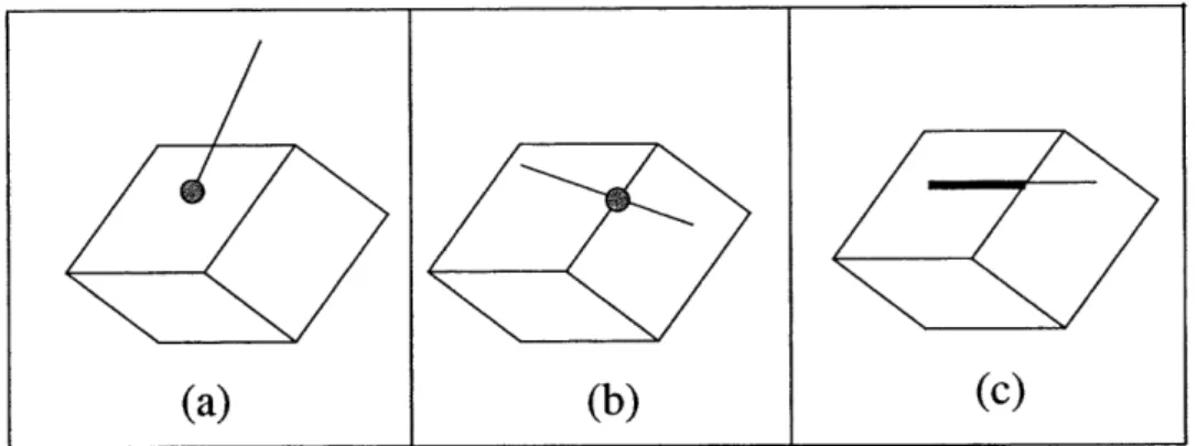
Compared to graphic VE, the programs for haptic VE do not have full control on the probe. The user is the one that controls the behavior of the probe. Therefore, the contact time between the probe and virtual objects is typically very long. This makes most of the algorithms in computer graphics inappropriate for computer haptics. One example is the simulation of a probe contacting a cube (see Figure 2-11). The probe approaches from the top to contact the cube (Figure 2-11(a)). Based on our daily experiences, we know that the probe should contact the top surface of the cube and the direction of the interacting force should always be up (Figure 2-11(b)). If we calculate the collision based on the
current configuration, we will get a wrong answer telling us that the probe is contacting the right surface of the cube (Figure 2-11(c)). And the direction of interacting force will be towards right side, which is not correct.
(a) (b) (c)
Figure 2-11. A simulation of a probe contacting a cube. (a) The probe approaches from
the top to contact the cube. (b) Based on our daily experiences, we know that the direction of the interacting force should always be up. (c) If we calculate the collision based only on current configuration, we will get a wrong answer telling us that the
direction of interacting force is towards the right side.
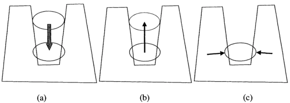
Other examples showing that the algorithms in computer graphics might give wrong answers could be found in Figures 2-12 to 2-14. In Figure 2-12, a long rod moves from the right side to contact a thin object (Figure 2-12(a)). The correct direction of interacting force should be towards right side (Figure 2-12(b)). However, most of the algorithms will suggest a direction either up or down (Figure 2-12(c)). In Figure 2-13, a thin paper moves towards another thin paper. The two papers are perfectly parallel. Since it is a discrete-time system, the program can update the position of the moving paper only in certain times. It is very likely that the moving paper passes the other paper between a time interval without contacting it. Therefore, no collision could be detected. In Figure 2-14, we try to simulate that an object moves towards a hole of another object (Figure 2-14(a)).
I
i
The ideal interacting force should be the one shown in Figure 2-14(b) since the object should be in the position indicated by the dash line. Using the existing algorithms, we will get wrong answers such as the one shown in Figure 2-14(c).
B
u
B
u
ii
Li
(a) (b) (c)Figure 2-12. A simulation of a long rod contacting a thin object. (a) The long rod moves
from the right side to contact a thin object. (b) The correct direction of interacting force should be towards the right side. (c) Most of the algorithms will suggest a wrong direction that is either up or down.
/5~~~
Figure 2-13. A thin paper moves towards another thin paper. The two papers are
perfectly parallel. It is very likely that the moving paper passes the other paper between a time interval without contacting it. Since no collision could be detected in either previous or current configurations, no interacting force would be sent to the moving paper.
i
-(a) (b)
Figure 2-14. A simulation that an object moves towards a hole of another object. (a) The
moving object moves from up towards down. (b) The ideal interacting force is towards up since the object should be in a position indicated by the dash line.. (c) With the existing algorithms, we will get wrong answers such as the one shown in the figure.
Chapter 3
Hardware Set-up and Software Architecture
3.1 Hardware Set-up
The minimum hardware requirement for creating a haptic VE includes a force-feedback haptic interface and a computer. The haptic interface could sense the position of the probe that is held by the user and send interaction force to users. The computer performs the process of haptic rendering. That is, for a given position information, a computer checks whether the probe is inside the virtual objects or not. If the probe is inside the virtual objects, it sends force commands to the haptic interface to make the user feel the objects. Usually the VE system will also includes a graphic display device (such as a monitor or a head-mounted display device) to let the users visually see the virtual objects. The hardware set-up for the VR systems used in this research includes a computer, a monitor, and a force-feedback haptic interface.
3.1.1 Haptic Interface for Point-Based Interaction
In order to apply the point-based rendering techniques, the haptic interface should have the ability to sense 3D positional information and send 3D force back to users. The haptic interface device that I have used for the point-based rendering is a commercial product available in the market (called PHANToM from SensAble Technology, Inc.). The PHANToM can reflect forces along three axes and sense 3 or 6 degrees of position information (depending on the models). The probe attached to the end of the PHANToM
could be a thimble in which the fingertip could be inserted (Figure 3-1(b)) or a stylus that could be held in the hand (Figure 3-1(a)).
(a) (b)
Figure 3-1. The PHANToM by SensAble Technology, Inc. Different probes could be
attached to the end of the PHANToM.
3.1.2 Haptic Interface for Ray-Based Interaction
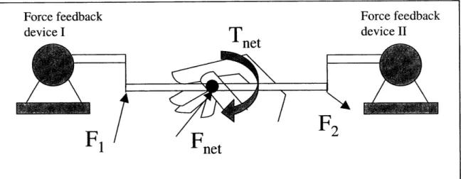
To implement the ray-based rendering techniques, the haptic interface device needs to have the ability to reflect back at least 5 DOF (degree of freedom) force. The haptic devices designed by Millman and Colgate (1991), Iwata (1993), and Buttolo and Hannaford (1995) are examples of such devices. To implement the ray-based algorithm, we have put together a haptic device set-up that is capable of displaying torques as well as forces. As mentioned earlier, the PHANToMs can reflect forces along three axes only. However, if two PHANToMs are connected to each other through a rigid probe, then a 5-dof force/torque display can be obtained (see Figure 3-2 and Figure 5-2). This configuration is the one we used to implement ray-based rendering and to conduct experiments described in Chapter 5.
...
0
Figure 3-2. Schematic description of our force-feedback haptic interface. In order to
display forces and torques to the user, we connected 2 force-feedback devices using a rigid probe. This enables us to display forces in 3 axes and torques about 2 axes (The torsion about the long axis of the probe cannot be displayed with this design).
3.2 Software Architecture
It is generally accepted that for the objects in VEs to appear natural, the graphic and haptic update rates need to be maintained at around 30 Hz and 1000 Hz, respectively. Therefore, to have optimal performance for a fixed computer power, the graphic and haptic loops have to be separated. There are two types of software architectures that can achieve this goal: multi-threading and multi-processing techniques (see Figure 3-3). In the multi-threading structure, both the graphic and haptic loops are processed in the same computer and share the same database. In this structure, the synchronization of the two loops in accessing to the data is important. In the multi-processing structure, the haptic and the graphic loops have their own copies of databases that are not shared. The two processes could run on the same machine or on different machines. The communication protocol between the two loops that ensure consistent between the graphic and haptic databases is important in this structure.
Based on our experience, both multi-threading and multi-processing techniques are quite useful in achieving stable haptic interactions and high graphic and haptic rendering rates. The choice of multi-processing or multi-threading structures should depend on the application. If the application requires large amount of data to be transferred between the two loops, we recommend multi-threading technique since it requires less programming effort and can achieve faster and more efficient communication. On the other side, if the application requires more computation or needs higher update rates, the multi-processing technique is recommended since it enables the user to process the two loops in two different machines.
(a) (b)
Figure 3-3. Software architectures for (a) multi-threading and (b) multi-processing. In
the multi-threading structure, both the haptic and the graphic loops share the same data. In this structure, the synchronization of the two loops in accessing the data is important. In the multi-processing structure, the haptic and the graphic loops have their own copies of data that are not shared. The two processes could run on the same machine or on different machines. The communication protocol between the two loops that ensure consistent update of both graphics and haptics data is important in this structure.
Chapter 4
Point-Based Interaction
One of the major concerns for haptic rendering is that the computational time usually increases when the number of polygons in the VE increases. In such a case, the quality of the haptic interaction will depend on the complexity of the environment. If the interacting forces cannot be updated at a sufficiently high rate, contact instabilities occur. In order to have stable haptic interactions, a haptic rendering algorithm that makes the computational time essentially independent of the number of polygons of an object would be quite beneficial. In this chapter, I present a haptic interaction paradigm called "Neighborhood
Watch" that utilizes a hierarchical database and a local search technique geared towards
achieving this goal. In this rendering algorithm, the computational model of the probe is simplified to a point and the virtual objects are represented as polyhedrons. The reason I focused on polyhedral objects is that any type of objects can be represented in polyhedral format within an arbitrary tolerance. Also, most of the digitized models of real objects are in polyhedral format.
4.1 Introduction
There are two important issues any haptic interaction paradigm has to specify. The first one is the collision detection that detects the collisions between the probe and the objects in the scene. The second one is the collision response that computes the response to collision in terms of how the forces reflected to the user are calculated. A good collision
detection algorithm not only reduces the computational time, but also helps in correctly displaying interaction forces to the human operator to make the haptic sensing of virtual objects more realistic. The collision detection and collision response techniques for haptics and graphics are slightly different. In computer graphics, collision detection (Cohen et al., 1995, Lin, 1993, Gottschalk, Lin, and Manocha, 1996, Smith et al., 1995, Hubbard, 1995) techniques are used to detect if two objects overlap. When the collision is detected, objects are separated from each other using collision response methods (Moore and Wilhelms, 1988, Baraff, 1994, Mirtich, 1995 and 1996). In general, the purpose of the collision detection and response in graphics is to avoid the overlap between objects and to simulate the behavior of objects following the overlap.
In contrast, the purpose of collision detection in haptic rendering is to check collisions between the probe and virtual objects to compute the interaction forces. When simulating interactions between the probe and the objects, the reflected force typically increases with penetration distance such that it resists the probe from further penetrating the object. Thus, the probe will always be inside the object during the collision response phase. This is a major difference between the collision response techniques developed for haptic and graphic interactions. In graphics, typically the existence of the overlap needs to be detected, followed by collision response algorithms to separate the overlapped objects. In haptics, the main goal is to compute the reaction force, instead of pushing the probe out of the objects. Hence the depth of penetration and how the penetration evolves are important. After detecting a collision between the probe and the objects, a simple
mechanistic model such as the Hooke's law (F = -k, where X is the penetration
vector) can be used to calculate the force.
One simple way to determine the depth of penetration is to use the shortest distance between the probe and the object's surface (Massie, 1993, Massie and Salisbury, 1994). This approach works well for primitive objects such as a cube, sphere, cylinder, etc. However, the drawbacks of this technique are that it cannot display the objects that are
small, thin, or polyhedral (Massie, 1993, Ruspini et al., 1996, 1997). Another approach to decide the depth of penetration is to use a constraint-based method (Zilles and Salisbury,
1995). This method defines an imaginary point, called the god-object point, which is constrained by the facets of the object. The penetration depth could then be defined as the distance from the god-object to the probe. This approach can be applied to polyhedral objects, even when the objects are thin or small. However, their proposed method requires different sets of rules to handle concave and convex objects. The "Neighborhood Watch" rendering algorithm presented in this chapter can handle both convex and concave objects uniformly. This algorithm is conceptually similar to the god-object algorithm (Zilles and Salisbury, 1995) but follows a different approach. The new approach reduces the computational time, makes the haptic servo rate independent of the number of polygons of the object, and results in more stable haptic interactions with complex objects.
In order to describe the concept more clearly for this approach, we need to define three types of probe. The first one is called real probe that is the physical piece held by the user and is the real 3D probe. The second one is called haptic interface point (HIP) that is the computational model of the real probe. It should be noted here that the probe is modeled as a point in this algorithm. The HIP could be the coordinate of the probe tip, the coordinate of the center of the probe, or the coordinate of a specific part of the probe. In the mathematical computation, the HIP is used to represent the real probe. The last one is called ideal haptic interface point (IHIP) that represents the ideal location of the HIP. The IHIP is similar to the god-object proposed by Zilles and Salisbury, 1995 or the proxy by Ruspini et al., 1997). Ideally, a probe cannot penetrate into any objects in a real world. Therefore, the IHIP is constrained so that it cannot penetrate into objects. If the HIP is outside the objects, the positions of IHIP and HIP will be the same. However, it the HIP moves into an object, the IHIP will be constrained to stay on the surface of the object.
The positions of HIP and IHIP play an important role in computing the interacting force (see section 4.4 for more details).
4.2 Hierarchical Database
In order to develop efficient collision detection and collision response algorithms, a processing stage called "processing phase" is needed. The function of the pre-processing phase is to arrange the data in a way such that it can help in later computation. In our pre-processing phase, we build two types of data to achieve faster collision detection: the hierarchical bounding-box tree and the connectivity information between primitives. The bounding-box tree is useful in determining the contact situation between the probe and the objects when there is no contact in the previous loop. Once a contact occurs, the connectivity information could be used to perform local search for the up-coming loops since we know the probe cannot move too far in a small amount of time (since the servo rate is around 1 kHz, and human motions are relatively slow).
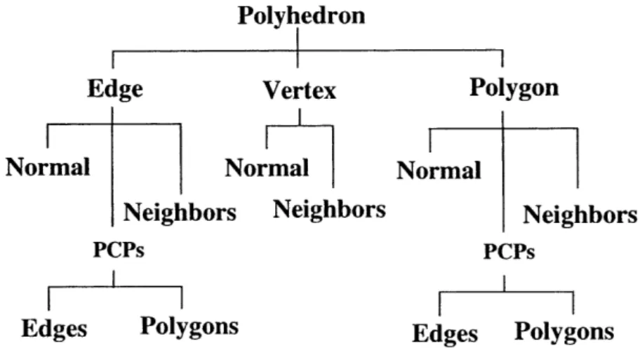
The first step in the pre-processing phase is to load/create the data for each object. The object data include the coordinates of each vertex and how the polygons are made from these vertices. After that, we construct another type of 2D geometrical primitive, namely, the lines that are simply the edges of the triangular polygons. As a result, the polyhedral objects in our own database are made of three types of 2D geometrical primitives: polygons, lines, and vertices. In order to implement a fast search technique for detecting collisions between the probe and 3D objects, we extend our database such that each primitive has a list of its neighboring primitives. Each polygon has neighboring primitives of lines and vertices, each line has neighboring primitives of polygons and vertices, and each vertex has neighboring primitives of polygons and lines (see Figure 4-1 and Figure 4-2). In addition to the connectivity information, we compute the normal vector of each primitive. For a polygon, the normal is the vector that is perpendicular to its surface and points outwards. For a line, its normal is the average of the normals of its
neighboring polygons. For a vertex, its normal is the average of the normals of its neighboring polygons, linearly weighted by the associated angle subtended at the vertex.
Polyhedron
I
I
I
Vertex Normal Neighbors Lines Poly! Line I Ig Normal Neighbors I~ N, Vertices Polygons gons Polygon Neighbors ormal Vertices LinesFigure 4-1. The connectivity information for primitives. The polyhedron representing the
object is composed of three primitives: vertex, line, and polygon. Each primitive is associated with a normal vector and a list of its neighbors.
(a) (b) (c)
Figure 4-2. Illustration of how the neighbors of a vertex, line, and polygon are defined.
(a) The vertex has six neighboring lines and six neighboring polygons. (b) The line has two neighboring vertices and two neighboring polygons. (c) The polygon has three neighboring vertices and three neighboring lines.
Another task performed in the pre-processing phase is creating the hierarchical bounding-box tree for each object (Gottschalk, Lin, and Manocha, 1996). At the top of the hierarchy is a bounding box that covers all of the polygons of the object. The polygons
are then separated into two groups based on their geometric centers. We then create a bounding box for each group. These two new bounding boxes are placed under the first bounding box in the hierarchical tree. We repeat the same process to create two children bounding boxes for each parent bounding box at each hierarchical level of the tree until there is only one polygon left in each bounding box (see Figure 4-3).
Figure 4-3. An example of hierarchical bounding-box tree. At the top of the tree is a
bounding box that contains all 12 polygons. The top bounding box is separated into two bounding boxes at the second level. The separation of bounding box continues until there is only one polygon in each of the box.
4.3 Collision Detection
When exploring virtual environments, we interact with virtual objects through the real probe, which is computationally modeled as the haptic interface point (HIP) in the VEs. As mentioned earlier, we create another point called ideal haptic interface point (IHIP) in our program to represent the ideal location of the HIP. The HIP is not constrained and, consequently, it can penetrate the surface of virtual objects. However, we constrain the IHIP such that it cannot penetrate any objects. When the HIP is in the free space of the virtual environments, the location of the IHIP will be coincident with the HIP. If the
movement of the HIP does not penetrate any object, the IHIP will keep following the path of the HIP. However, if the HIP moves into a virtual object, the IHIP will stay on the surface of the object. To computationally achieve this concept, we keep track of the path of HIP and check if this path penetrates any polygon. We construct a line segment between the coordinates of the HIP in the previous and current loops. We then detect whether this line segment (since the servo rate is around 1 kHz, and human motions are relatively slow, this line segment is very short) has an intersection with the polygons of the 3D objects or not. To achieve fast checking, we utilize "hierarchical bounding boxes" approach (Gottschalk et al., 1996). We first check whether the line segment is inside the bounding box of the objects or not. If it is outside of the bounding box, the line segment cannot have an intersection with the polygons. If it is inside the bounding box, we then check if the line segment is inside any of the two children bounding boxes in the next level of the hierarchical tree. If the line segment is outside the bounding box, the check is stopped. However, if the line segment is still inside one of the bounding boxes, we check with the lower level of that bounding box in the hierarchical tree again. As intersections are detected with successive bounding boxes along one particular branch of the tree, the last intersection is checked between the line segment and the polygon that is inside the lowest level of bounding box of the tree. If the line segment penetrates a polygon, we set this polygon as the contacted geometric primitive. The IHIP will then be constrained to stay on the surface of this polygon. The nearest point from this polygon to the current HIP is set as the IHIP and the distance from the IHIP to the current HIP is set as the depth of penetration. Although the first contacted geometric primitive is always a polygon and the IHIP is assigned to be on the surface of this polygon, it can easily be a line or a vertex in subsequent iterations.
Once the first contact is detected, we can use the local search techniques to reduce the computational time for the subsequent loops. The concept to support the local search techniques is that the probe cannot move too far away from the current position in just
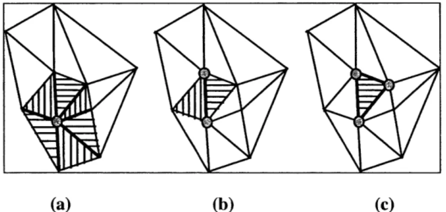
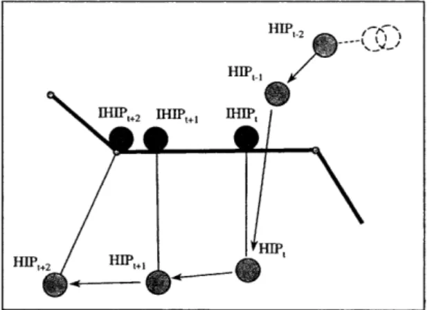
one loop. (Since the typical servo rate is around 1 kHz and human motions are relatively slow, the movement of the probe in one loop is usually less than one millimeter.) Therefore, if we know the contacted geometric primitive in the previous loop, we can start from that primitive and check collision only with its neighbors. The connectivity information described in the previous section is used to perform this local search. The local search approach significantly reduces the number of computations and also makes them essentially independent of the number of polygons that represent the objects. So, in the next iteration, we calculate the nearest distances from the current HIP to the contacted geometric primitive and its neighboring primitives. For example, if the contacted primitive is a polygon, then we check the distance from the current HIP to the neighboring lines and vertices. If the contacted primitive is a line, we check the distance from the current HIP to the neighboring polygons and vertices. Then, we set the primitive that has the shortest distance to the current HIP as the new contacted geometric primitive and move the IHIP to a point that is on this primitive and nearest to the current HIP (see Figure 4-4). This rule-based algorithm is repeatedly applied for the ensuing interactions. From the description in Figure 4-5 and Figure 4-6, we can see that this rule-based algorithm works with both non-convex and thin objects
FHIP+
Figure 4-4. Haptic interactions between the probe and 3D objects in VEs. Before the
collision occurs, HIP is outside the object surface and is identical with IHIP (see HIPt-3,
HIPt2, and HIPt_1). When the HIP penetrates into object at time t, the IHIP is constrained
to stay on the surface. At time t+l, HIP moves to a new location (HIPt+l) and the new location of IHIP is determined by the current HIP and the neighboring primitives based on the nearest distance criterion.
Figure 4-5. Haptic interactions between the probe and a non-convex object in VEs.
Before the collision occurs, HIP is outside the object surface and is identical with IHIP
(see HIPt_2 and HIPtl1). When the HIP penetrates into object at time t, the IHIP is
constrained to stay on the surface. At time t+l and t+2, HIP moves to new locations
(HIPt+1and HIPt+2). The nearest distance criterion could be used to find the new locations
of IHIP. HIP -A-_1 HIP, KvelIP t+ fa IP HIP, I I I k1Irt HIP,., " V I
HlPt-2 Am v by)
HIPt-1 /
HT, , i· 1
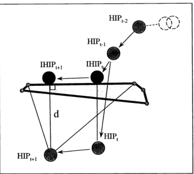
Figure 4-6. Haptic interactions between the probe and a thin object in VEs. Before the
collision occurs, HIP is outside the object surface and is identical with IHIP (see HIPt_2
and HIPt-). When the HIP penetrates the object at time t, the IHIP is constrained to stay on the surface (IHIPt). At time t+l, HIP moves to a new location (HIPt+i). The nearest distance criterion will still work in finding the new location of IHIP.
In each cycle, we also need to check if the current HIP is still inside the virtual object. For this purpose, we construct a vector from the current HIP to the IHIP. If the dot product of this vector and the normal of the contacted primitive is negative, the current HIP is no longer inside the object and there is no penetration any more. If the dot product is positive, then the current HIP is still inside the object. The pseudo-code for this "Neighborhood Watch" haptic interaction algorithm is given below.
if (collision == FALSE)
if (the path of HIP penetrates a polygon)
Set the polygon as the contacted geometric primitive;
Move the IHIP to a point on this polygon that is closest to the HIP;
collision <-- TRUE;
else
contacted geometric primitive <- the contacted geometric primitive in the previous loop;
primitive <- contacted geometric primitive;
distancel <-- closest distance from current HIP to primitivel;
repeat {
primitivel = contacted geometric primitive;
for ( i = 1: number of neighboring primitives of primitivel)
primitive2 4-the ith neighboring primitive of primitivel;
distance2 <-- distance from current HIP to primitive2;
if (distance2 < distancel)
contacted geometric primitive - primitive2; distancel - distance2;
} while (primitivel != contacted geometric primitive)
Move IHIP to a point that is nearest from the contacted geometric primitive to current HIP
vectorl - vector from current HIP to current IHIP;
normall <- normal of the contacted geometric primitive;
if (dot product of vectorl and normall < 0)
collision - FALSE;
Using this algorithm, we can render both convex and concave objects in an efficient manner. The computational time for detecting the first collision will be in the order of log(N) for a single object, where N is the number of polygons (Gottschalk et al., 1996). After the first collision, we only calculate the distances from the current HIP to the contacted primitive and its neighbors to determine the new location of IHIP. Therefore, the servo rate will be fast since it only depends on the number of neighbors of the
contacted geometric primitive. For a homogeneously tessellated polyhedron, as N increase, because the number of computational operations for searching the neighbors of each primitive is about the same, the servo rate will continue to be independent of the total number of polygons after the first collision.
4.4 Collision Response
In haptic rendering, the collision response focuses on the computation of reaction force that arises from the interactions between the probe and the 3D objects. Although the collision response phase has been studied in computer graphics (Baraff, 1994; Mirtch and Canny, 1995; Moore and Wilhelms, 1988), its implementation to haptics shows some differences.
The first step in collision response phase is to find the penetration depth. In this "Neighborhood Watch" algorithm, the penetration depth is simply the position difference between the HIP and the IHIP and the penetration direction is from the IHIP to HIP. Then, the interacting force could be computed based on the penetration depth. One way to calculate the force is to use a simple mechanistic model such as the Hooke's law
(F = -k, where k is the spring constant and represents the material stiffness, X is the penetration vector starting from IHIP to HIP, see Figure 4-7). We can choose a larger k to simulate a stiff object or choose a smaller k to simulate a soft object. A damping term (- bx) could be added to the model to add the damping effect. We can also change the
IHIP
Figure 4-7. When the HIP penetrates into an object, the IHIP stays on the surface. The
penetration vector X is defined such that it points from the IHIP to HIP.
4.5 Results
I have successfully applied the rendering techniques described in this chapter to render
various objects both on a Windows NT platform and a Unix platform (see Figure 4-8 and 4-9). In order to demonstrate the efficiency of our haptic interaction technique, we did a test to compare the rendering rate for different objects. The structure of the programs includes two separate loops, one for updating graphics and the other for displaying force. The graphics update rate is around 30. The polygon number of the objects we tested ranges from hundreds to thousands (see Table 4-1). It can be seen from table 4-1 that the haptic servo rate is approximately constant even if the number of polygons is increased by approximately 5000 times.
Figure 4-8. Rendering of various 3D virtual objects. The small dark dot represents the
haptic probe. The user uses this haptic probe to interact with the virtual objects.
(a) (b)
Figure 4-8. Rendering of 3D virtual organs. (a) The small dark dot represents the haptic
probe. The user uses this haptic probe to interact with the virtual organs. (b) The virtual organs are all polyhedrons composed of triangular polygons.
Table 4-1. Haptic rendering rates for various 3D rigid objects. The results were obtained
with a Pentium II, 300 MHz PC running two threads and equipped with an advanced graphics card (AccelECLIPSE from AccelGraphics). Servo rate results are based on rendering 3D objects for at least 3 minutes. Rendering test is repeated at least three times for each object.
Object 1 Object 2 Object 3 Object 4
Number of vertices 8 239 902 32402
Number of lines 18 695 2750 97200
Number of polygons 12 456 1800 64800
Chapter 5
Ray-Based Interaction
Most of the haptic rendering techniques developed so far are point-based in which the probe is simplified to a point. This approach is computationally less expensive, but it only enables the user to feel interaction forces, not the torques. Since the probe is modeled as a point, the net force is the only haptic feedback that could be sent to the user. For exploring the shape and surface properties of objects in VEs, these methods are probably sufficient and could provide the users with similar force feedback as what they would get when exploring the objects in real environments with the tip of a stick. However, point-based methods are not sufficient to simulate tool-object interactions that involve multiple constraints. The computational model of the simulated tool cannot be reduced to a single point since the simulated tool can easily contact multiple objects and/or different points of the same object simultaneously. Moreover, the resulting reaction torque has to be computed and reflected to the user to make the simulation of haptic interactions more realistic.
Modeling haptic interactions between a probe and objects using ray-based technique has several advantages over the existing point-based techniques. First of all, side collisions between the simulated tool and the 3D objects can be detected. User can rotate the haptic probe around the corner of the object in continuous contact and get a better sense of the object's shape. In point-based methods, one of the common unrealistic feelings is that the user's hand could go inside the objects although the point probe is still outside (see Figure
5-1). This situation could be eliminated using ray-based rendering. Second, ray-based rendering provides a basis for displaying torques to the user. Using the ray-based rendering algorithm, we can compute the contact points, depth of penetration, and the distances from the contact points to both ends of the probe. Then, we use this information to determine the forces and torques that will be displayed to the user. Third, the ray that represents the probe can be extended to detect the collisions with multiple layers of an object (in fact, this is the reason why we name the technique as ray-based). This is especially useful in haptic rendering of compliant objects (e.g. soft tissue) or layered surfaces (e.g. earth's soil) where each layer has a different material properties and the forces/torques depend on the probe orientation. Fourth, it enables the user to touch and feel multiple objects at the same time. If the task involves the simulation of haptic interactions between a tool and an object, ray-based rendering provides a more natural way of interacting with objects. Fifth, the reachable haptic workspace can potentially be extended using this technique since we have the full control of forces and torques that are displayed to the user. This means that it may be possible to create an illusion of touching distant objects by virtually extending the length of the probe and appropriately changing the direction and magnitude of the reflected forces (similar to seeing distant objects with a flash light, see Figure 5-2).
Real World Point-Based Ray-Based
/- /,1
Figure 5-1. The difference in point- and ray-based rendering techniques: In point-based
rendering, the haptic probe is modeled as a single point leading to artifacts such as feeling the bottom surface of the object by passing through the object. In ray-based rendering, end point as well as side collisions are detected between a line segment and virtual objects.
Figure 5-2. (a) Our two-PHANToM set-up for displaying forces and torques to the user
using ray-based haptic rendering algorithm. (b) The reachable haptic workspace can potentially be extended using this technique since we have the full control of forces and torques that are displayed to the user.
For example, in performing minimally invasive surgeries, the surgeon inserts thin long rigid tubes into the body of the patient through several ports. Small size instruments
I
attached to these tubes are used for manipulating internal organs. During the surgery, surgeon accesses the targeted area by pushing the organs and surrounding tissue to aside using the instruments and feels both the interaction forces and torques. A point-based technique is inadequate to fully simulate such haptic interactions between surgical instruments and virtual organs. If the instrument is modeled as a single point, the side collisions of an instrument with organs will not be detected and the instrument will pass through any organ other than the one touching the tip. We have observed that simulation of haptic interactions between the line segment models of laparoscopic instruments and organs using the ray-based technique could significantly improve the realism (Basdogan et al., 1998). In addition, multi-layered and damaged tissues whose reaction forces depend on the tool orientation can be simulated better using the ray-based technique since the ray can be extended along the contacted surface and the contacts in multiple layers
could be detected to compute interaction forces.
Another example where the ray-based rendering is preferable would be the simulation of assembly line in car manufacturing. A scenario may involve a mechanic to go under a virtual car and turn the nuts of an engine block. Some of these procedures are done through mechanical instruments attached to a long and rigid shaft that enables the mechanic to reach difficult areas of the engine. Typically, the vision is limited and the mechanic finds his way around using haptic cues only. Moreover, the path to the nuts is usually blocked by several other mechanical components that make the haptic task even more challenging. The simulation of this procedure in virtual environments will certainly involve the modeling of torques and detection of multiple collisions simultaneously since a long rigid shaft is used to reach the targeted areas.
The details of the ray-based rendering techniques are presented in this chapter. In section 5.1, a general introduction of ray-based rendering is presented first. Following the introduction is the hierarchical database in section 5.2. The hierarchical database for ray-based is extended from the one for point-ray-based. The collision detection and the collision