HAL Id: hal-01378849
https://hal.archives-ouvertes.fr/hal-01378849
Submitted on 10 Oct 2016HAL is a multi-disciplinary open access
archive for the deposit and dissemination of sci-entific research documents, whether they are pub-lished or not. The documents may come from teaching and research institutions in France or abroad, or from public or private research centers.
L’archive ouverte pluridisciplinaire HAL, est destinée au dépôt et à la diffusion de documents scientifiques de niveau recherche, publiés ou non, émanant des établissements d’enseignement et de recherche français ou étrangers, des laboratoires publics ou privés.
THE C70 ARRONAX AND BEAM LINES STATUS
Freddy Poirier, Sebastien Girault, Stephane Auduc, Christophe Huet, Erwan
Mace, Jean-Luc Delvaux, Ferrid Haddad
To cite this version:
Freddy Poirier, Sebastien Girault, Stephane Auduc, Christophe Huet, Erwan Mace, et al.. THE C70 ARRONAX AND BEAM LINES STATUS. IPAC11, Sep 2011, San Sebastian, Spain. �hal-01378849�
THE C70 ARRONAX AND BEAM LINES STATUS
F. Poirier, S. Girault, ARRONAX, Saint-Herblain, France, IN2P3/SUBATECH, Nantes, France
S. Auduc,
ARRONAX, Saint-Herblain, France
C. Huet, EMN, Nantes, France, IN2P3/SUBATECH, Nantes, France
E. Mace, INSERM, Nantes, France, IN2P3/SUBATECH, Nantes, France
J.L. Delvaux, IBA, Louvain-la-Neuve
F. Haddad,IN2P3/SUBATECH, Nantes, France
Abstract
The C70 ARRONAX is a high intensity (up to 2x375A) multi-particle cyclotron aiming at R&D on material and radiolysis and production of radioisotopes. It began its hands-on phase in December 2010, and is currently undergoing beam lines’ modification in experimental halls for present and future experiments.
Characterisation of the beams at the end of beamlines is of particular importance to determine the capacity of the cyclotron for end-line experimental users. A program of beam characterisation is being performed based in one hand on dedicated diagnostics e.g. beam profilers, faraday cups, alumina foils and in the other hand on a series of Geant4 beam simulations. The out coming results of the measurements, along with the simulations, are detailed in this report for proton and alpha particle beams, as well as the future prospects of the characterisation program.
INTRODUCTION
ARRONAX, an acronym for "Accelerator for Research in Radiochemistry and Oncology at Nantes Atlantique", is a high energy (70 MeV for protons) and high intensity (2x375µA for protons) multi-particle accelerator located in Nantes, France. ARRONAX can deliver beams in 6 experimental vaults: four are devoted to radionuclide production and equipped with an irradiation station connected to our hot cells via a rabbit system; one contains a neutron activator being tested at the time of writing; the last one is used for basic research in radiolysis, radiobiology and physics especially using the alpha and deuteron beams. The cyclotron reached its full specifications (24H in a row at 750µA for protons) in October 2010 but irradiations at low current started in March 2010 forradiochemical studies and process optimisations. During 2010 ARRONAX staff worked to be acquainted with the operation of such a unique cyclotron. 2011 is the hands-on phase, with an extensive program on optimisation of the beams and exploration of beam parameters for the users.
Characterisation of the beams at the end of the beam lines is particularly important to determine the capacity of the cyclotron for the end-line experimental users. Production of non-conventional radioisotopes for nuclear medicine requires tens of µA on targets whereas, physics experiments like PIXE use only nA currents.
A program of beam characterisation is being performed, based on dedicated diagnostics, e.g. beam profilers, faraday cups, alumina foils, and also on a series
of Geant4 beam simulations. The outcoming results of the measurements, along with the simulations, are detailed in this report as well as the future prospects of the characterisation program.
C70 ARRONAX
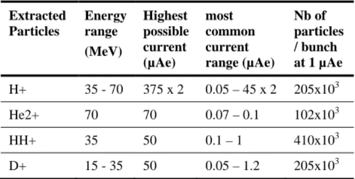
ARRONAX is an isochronous cyclotron with 4 high hill sectors. The overall size of the cyclotron is of the order of 4m. The working RF frequency is 30.45 MHz with an RF cavity composed of two dees at a voltage of 65 kV. Table 1 summarises the characteristics of the beam for the four types of particles. Alpha (He2+) particles can undergo a stretch of the inter-bunch time in the experimental hall as described below.
Table 1: C70 Characteristics Extracted Particles Energy range (MeV) Highest possible current (µAe) most common current range (µAe) Nb of particles / bunch at 1 µAe H+ 35 - 70 375 x 2 0.05 – 45 x 2 205x103 He2+ 70 70 0.07 – 0.1 102x103 HH+ 35 50 0.1 – 1 410x103 D+ 15 - 35 50 0.05 – 1.2 205x103
In the first half of 2011 a library of more than 50 beam settings has been established including beams with a large variety of modified parameters such as energy, beam transverse size, particles and beamlines. This is part of a continuing effort to accommodate the beam to the requirements of the end-station users and to optimise the beam performances.
BEAMLINES
Five vaults each house a single end-station, and one vault has three, i.e. 8 beamlines in total are in use at ARRONAX. Beamlines are basically constituted – from the cyclotron downward to the end-station – of a switching magnet, a double y-x steerer, 2 quadrupoles (10T/m max), a faraday cup, 2 quadrupoles, another faraday cup and a collimator as shown in figure 1:
The switching magnets have the purpose to bend the beam in a dedicated line.
The faraday cups pick up current up to 210 µA at 70 MeV, i.e. 15 kW.
Proceedings of IPAC2011, San Sebastián, Spain WEPS069
04 Hadron Accelerators
A12 FFAG, Cyclotrons 2661 Copyright
c○ 2011 by IP A C’11/EPS-A G — cc Cr eati v e Commons Attrib ution 3.0 (CC BY 3.0)
The collimator is made of 4 independent fingers which measure the current when the beam is large enough at this location to make deposition. Targets can be placed in vacuum using the IBA
target station or in air by placing a Kapton foilat the end of the beam line. Typical thickness of 75 µA is used allowing 1 µA 16 MeV deuteron beam on 10mm diameter target.
The 6th vault is equipped with an additional switching magnet leading to three more beamlines, each constituted of a steerer, 2 quadrupoles and a faraday cup. One line includes also a vertical dipole for experiments requiring a top-bottom beam direction.
Figure 1: Elements constituting a typical basic beamline. Here an alumina foil (AlO3) is located at the end-station.
Strategy for Beam Transport
The employed strategy to transport the beam from the exit of the cyclotron downstream to the experimental hall is dependent on the end-station of the line in use and specific needs for the users in terms of transverse beam. At high current and with samples in a rabbit, the target is straight behind the collimator so the quadrupoles strength are modified such that a small percentage of the beam is deposited equally on each finger. For experiments with specific needs regarding current and transverse size (smaller than the collimator opening) the target is positioned far (0.5 to 1 m) from the collimator. In such a case beam size optimisation is required. At the present time this optimisation is only applied to low intensity beams (<1.2 µA).
The Optimisation is based on two main steps:
The first step is the optimisation of the beam current along the beamline such that losses are minimised. The beam current optimisation is mostly based on modifying the switching magnets’ strength, and relies on checks with the faraday cups.
The second step is part of an on-going effort to get the transverse beam, as required to a target position. It relies on modification of the bending magnets and quadrupoles’ strength one by one and to ensure, in the end, that only beam transverse size is changed using quadrupoles. Several iterations over the magnets are necessary to align the beam axis to the quadrupole. This checking is performed with the alumina foils and profiler described below.
Beamline Simulation
A preliminary simulation performed with G4Beamline [3], including a description of the magnetic elements and collimators, has been developed in parallel and is illustrated in figure 2.
Implemented for 68 MeV protons, the simulation has indicated the location of particles losses along the beamline and the expected beam size at the end of one line. This is a crucial tool which will serve as a basic benchmark for further characterisation and for decision on strategies to be employed for the transport of the beam.
Figure 2: Layout of the G4Beamline simulation.
Profiler Measurements
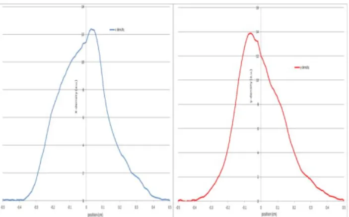
Single-wire NEC beam profilers at a frequency of ~18Hz have been installed downstream the collimators on several lines. These are used to measure the profile while the beam is sent to the target and to insure transverse size modification when changing the magnets’ strength. The profiler can withstand ~150 µA for a 10mm diameter beam. Figure 3 shows one profile measurements in the y-x axis for an average of ~1.7 million beam crossings.
Figure 3: y-x density profile performed at a low intensity beamline.
The full width half maximum is x=0.326+-0.009 cm and y=0.297+-0.009 cm, indicating a rather small and round transverse size at the profiler location. The strategy described earlier was utilised to get to this result.
Alumina Foils
Alumina foils have been used to check the transverse size and position of beams less than 150 nA for protons and alpha. The foils are centred downstream of the beamline just behind a kapton exit window. They help in optimising size-wise and centering the beams at the location of the user’s experiments. Due to the afterglow
WEPS069 Proceedings of IPAC2011, San Sebastián, Spain
2662 Copyright c○ 2011 by IP A C’11/EPS-A G — cc Cr eati v e Commons Attrib ution 3.0 (CC BY 3.0) 04 Hadron Accelerators A12 FFAG, Cyclotrons
of the alumina no trigger synchronised to the bunch crossing is implemented. A radiation hard Vidicon camera installed at approximately 30 degrees from the beam axis, collects the light signal.
Figure 4 shows the results with a proton beam. The transverse size given on the foils is approximately 1 cm. At present time, a matlab code is being devised to analyse data off-line. It is foreseen in the future to perform correlation measurements between the aluminiumfoils and BPM.
Figure 4: A typical proton beam on the alumina foil. The bars on crossing lines mark 0.5 cm from the center.
ALPHA PARTICLE BEAMS
The alpha particle beams delivered to the end of the line have a 32.8 ns inter-bunch time, as shown in figure 5. This time is defined by the cyclotron RF. The combination of an aperiodic deflector in the injection, and an additional cavity based RF deflector in the beamline, allows to increase the inter-bunch time. This system is installed upstream of the three beamlines in the 6th vault. The purpose of the RF deflector is to kick away bunches, such that they are out of the beam-line axis and are stopped in a downstream collimator, leaving bunches going downstream the beamline twice the RF deflector frequency.
The deflector is at 50 kV with afrequencyof 1.5 MHz minimum. The repetition frequency is variable such that the inter-bunch time can be varied from 330 ns (figure 6) to 5s.
Figure 5: Alpha beam bunch spacing (32.8 ns) without deflectors.
Figure 6: Bunch spacing (330 ns) with the RF deflector.
CONCLUSION
A large library of beams is being made available to the end-station users at ARRONAX. The diagnostics, such as profiler, alumina foils and faraday cups, are systematically used to build up the beams. Additionally, a strategy for the beam transport and Geant4 simulations is being applied to allow for better optimisation. This work is part of a strong effort of the maintenance and operation group in the characterisation program of the ARRONAX cyclotron.
PERSPECTIVES
Offline and online analysis tools, including the present diagnostics (alumina foils and profilers), will be developed such that more thorough understanding of the beam is achieved. This will also include a long-term study on the beam repeatability of the machine. Further diagnostics, such as beam loss and position monitors, are being studied for later installation in the beamlines and an in-house made energy degrader will be put in by 2012. All of this work is a preliminary step towards emittance measurements and consolidations of the techniques used for beam transport down the beamlines.
ACKNOWLEDGMENT
One of the authors, F.P., would like to thank the preliminary work on simulations performed by W.Tan.
REFERENCES
[1] J. Martino, “ARRONAX, a 70 MeV cyclotron for Radiochemistry and Nuclear Medicine”,Proc. 18th Conf. on Cyclotrons and their Applications, Catania 2007.
[2] L. Medeiros Romaoet al,“IBA C70 Cyclotron Development”, Proc. 18th Conf. on Cyclotrons and their Ap., Catania, 2007, and references therein.
[3] T.J. Roberts et al, “G4beamline Simulation Program for Matter dominated Beamlines”, EPAC08-WEPP120, June 2008.
Proceedings of IPAC2011, San Sebastián, Spain WEPS069
04 Hadron Accelerators
A12 FFAG, Cyclotrons 2663 Copyright
c○ 2011 by IP A C’11/EPS-A G — cc Cr eati v e Commons Attrib ution 3.0 (CC BY 3.0)