Publisher’s version / Version de l'éditeur:
Canadian Geotechnical Journal, 6, 1, pp. 17-32, 1969-01-01
READ THESE TERMS AND CONDITIONS CAREFULLY BEFORE USING THIS WEBSITE. https://nrc-publications.canada.ca/eng/copyright
Vous avez des questions? Nous pouvons vous aider. Pour communiquer directement avec un auteur, consultez la
première page de la revue dans laquelle son article a été publié afin de trouver ses coordonnées. Si vous n’arrivez pas à les repérer, communiquez avec nous à [email protected].
Questions? Contact the NRC Publications Archive team at
[email protected]. If you wish to email the authors directly, please see the first page of the publication for their contact information.
NRC Publications Archive
Archives des publications du CNRC
This publication could be one of several versions: author’s original, accepted manuscript or the publisher’s version. / La version de cette publication peut être l’une des suivantes : la version prépublication de l’auteur, la version acceptée du manuscrit ou la version de l’éditeur.
Access and use of this website and the material on it are subject to the Terms and Conditions set forth at
Earth pressures on Ottawa outfall sewer tunnel
Eden, W. J.; Bozozuk, M.
https://publications-cnrc.canada.ca/fra/droits
L’accès à ce site Web et l’utilisation de son contenu sont assujettis aux conditions présentées dans le site LISEZ CES CONDITIONS ATTENTIVEMENT AVANT D’UTILISER CE SITE WEB.
NRC Publications Record / Notice d'Archives des publications de CNRC:
https://nrc-publications.canada.ca/eng/view/object/?id=d4dd6719-f03c-4f09-925a-8c185d2105ac https://publications-cnrc.canada.ca/fra/voir/objet/?id=d4dd6719-f03c-4f09-925a-8c185d2105ac
EARTH PRESSURES ON 0TTAWA.OUTFALL
SEWER TUNNELls2
W. J. E D E N and M. BOZOZUK Soil Aiiecllanics Section, Divisioia of Building Research, Nationnl Research Council of Canada, Ottat~:a, Canarln
l\4easurements of surface settlement, changes in piezo~nctric levels and earth prcssmcs werc undertaken on a 10-ft diameter tunnel that passed through ex- tremely scnsitive and moderately over- consoliclatccl Leda clay in Ottawa. T h e instrunlcntation is described, and the rcsults arc given for a period of 5 years, from 1 year before construction until 4 years after completion. Results of t l ~ e rneasuremcnts are compared with those obtained from a tunnel of similar size in Detroit clay. Because of the method of construction there was opportunity to conduct measuremcnts on both the rather flcsiblc temporary stcel lining and the inore rigid pcrnmanent reinforced concrete lining.
Very littlc surface settlement was mea- sured owing to overconsolidation of the clay and the metliod of construction. T h e tunnel had considerable influence on the l~iczometric regime in thc clay, acting as a clrainagc sink. Earth pressures were in accordance with previous mcasurements on tunnels, with vertical prcssurcs ap- proaching the full overburden pressure.
Des mesurcs cle tasscment de surface, change- n ~ e n t s d c niveaux piBzom6triques et de pressions des terres ont &ti: cntreprises sur un tunnel de 1 0 piecls de diarnktre, percC clans de I'argile Leda IQgkrement surconsolidCe et estr&mement sen- sible, h Ottawa. L'instrumentation cst dCcrite et les r6sultats sont clonnCs pour une pCriode de 5 ans, c o m m e n p n t un an avant la construction ct finissant quatre ans aprks l'achkvement des travaus. Les rksultats des mesures sont cornparks
i ceus obtenus sur un tunnel de dimensions simi- laires dans I'argile cle Detroit. Du fait de la mCthode d e construction il a CtB possible de faire cles mesures sur le blindage temporaire d'acicr, plutbt flexible, et sur le reviitement permanent cle bCton armk, plus rigicle.
Des tasscments de surface triis faibles ont CtC mesurks, clus i la surconsoliclation de l'argile et i la m6thocle cle construction. Le tunnel a e u unc influence consiclCrable sur le rCgime piCzo- mCtricluc clans l'argile, d u fait cle son action d e trancl1i.c drainante. Les pressions cles terres ont 6tC trouvkcs conformes A des mesures antkrieures faites sur des tunnels, les pressions verticales approchant In pleine pression gkostatique.
INTRODUCTION
In 1958 the City of Ottawa embarked on an extensive sewage treatment program. Two main features were involved: ( 1 ) the construction of a sewage treatment plant with a capacity for 40 000 000 @/day on the eastern limits of the city; and ( 2 ) a main outfall sewer tunnel running parallel to the Ottawa
lNRCC No. 10516.
2Prescnted at the 21st Canadian Soil blcchanics Conference, Winnipeg, Manitoba, Septem- ber 12-13, 1968.
18 CANADLiN GEOTECI-INICAL JOURNAL
River and terminating at the treatment plant. The tunnel near its eastern end was to have an inside diameter of 8 ft. The outfilll sewer tunnel was constructed for the most part in bedrock, but the last mile was driven through extremely sensitive Leda clay.
With the cooperation of the City of Ottawa, the consulting engineers and the contractors, the Division of Building Research, National Research Council of Canada, undertook an experimental program to measure the earth pressures on the tunnel structure and the ground movements and changes in piezometric levels resulting from tunnel construction in the clay section.
TUNNEL STRUCTURE
The tunnel invert is founded at an average depth of 65 ft below the surface. The outside diameter is 10 ft, the inside diameter of the completed structure,
8 ft. The tunnel was driven from its west end by a rotary tunnelling machine and lined immediately with corrugated segmental steel liner rings. About 0.3 kg/cm%ir pressure was maintained in the tunnel to assist with support during excavation.
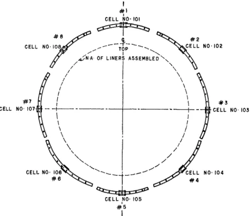
Each liner ring consists of eight segments forming a circle. The top segment was placed first and the bottom segments last. To ensure good contact with the clay the bottom liner segment was placed by jacking it against the neighboring segments. When necessary, grout was pumped into any space between the clay and the liner ring. Because of the well-trimmed excavation made by the machine, little grouting was required, and in general the liner was in close con- tact with the surrounding clay.
Excavation for the tunnel section in clay began in July 1961 and continued to 1 December 1961. On completion of the excavation and lining the air pressure was reduced to atmospheric, and work proceeded on the installation of the concrete, beginning at the eastern end. The reinforced concrete, 1 ft thick, was placed in two stages. The first stage was about ?.[-section placed at the invert; the nest stage completed the structure. The corrugated steel lining was left in place. By this method the tunnel was temporarily supported by a relatively flexible corrugated steel lining, and the con~pleted structure is a relatively rigid reinforced concrete section.
SITE CONDITIONS
For the entire length of the clay section soil conditions are uniform; the sur- face is level, with a fairly high groundwater table. Down to the depth of the tunnel the entire soil profile consists of Leda clay. From 0 to 8 ft it is friable and oxidized; from about 8 to 45 ft, quite stiff and relatively insensitive
( S t a~proximately 20). The natural water content averages 62%, tlle liquid limit 60%, and the plasticity indes 35%. Below this depth the clay is slightly coarser, with a natural water content of 50%. Sensitivity of the lower clay is very high, in the order of 600, but in spite of this the undisturbed clay behaved as a stiff brittle material during excavation. The depth of clay is somewhat variable, ranging from about 65 ft below the surface at the west end to about 75 feet at the east end. The clay is over-consolidated by about 3 tons per sq. ft throughout the length of the tunnel.
EDEN AND DOZOZUIC: O T T A W A O U T F A L L S E W E R
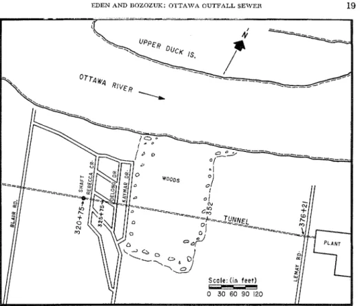
FIG. 1. Plan of tunncl.
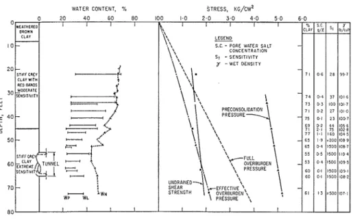
Figure 1 is a plan of the tunnel section in clay, showing the location of the test installations at stations 325+75 and 376+21. Figure 2 is the log of a boring at the eastern end of the tunnel, and can be considered representative of the area. A feature of the site is the esistence of a downward piezometric gradient in the clay. The change in eff'ective stresses owing to the piczometric gradient is shown in Fig. 2. Because of the clo~vn\varcl gradient, the effective stresses at the tunnel level are 1.0 kg/cm2 in excess of thosc that would prevail under hydrostatic conditions.
INSTRUMENTATION
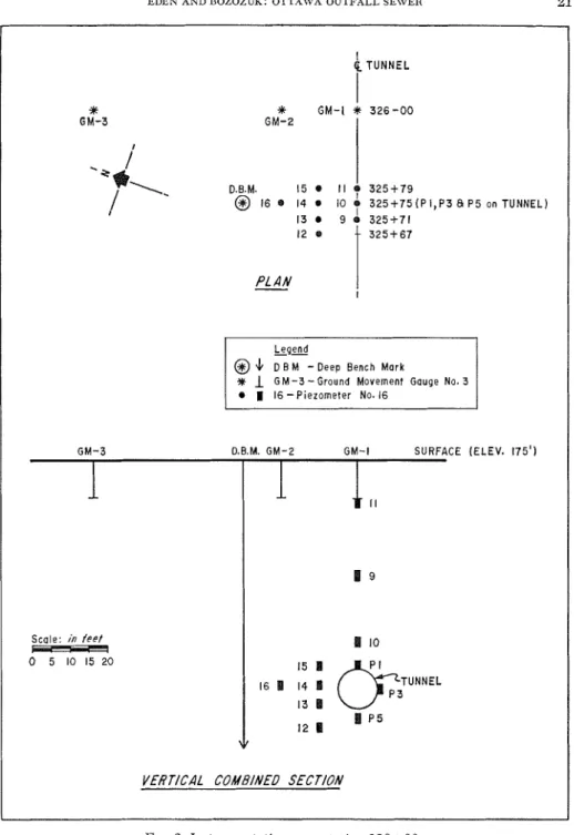
Instrumentation consisted of settlement or ground movement gauges, piezorn- eters, earth pressure cells, and deformation-ineasurillg devices. The settlement gauges were installed near the west end of the tunnel and were intended to monitor any surface movements caused by the tunnel construction and any settlements subsequent to construction. The installation at station 326+00 con- sisted of three ground-movement gauges (Bozozuk 1968), each at a depth of 10 ft, located on the centerline 25 and 50 ft north of the tunnel. Movements of these points were measured with reference to a deep bench-mark by precise levelling. Ground-movement gauges were installed in June 1961, but were destroyed by a bulldozer after three months of observation.
Eleven piezometers were installecl between stations 322+75 and 325+75 to measure the effects of tunnel construction on piezornetric conditions. These
20 CANADIAN GEOTECHNICAL JOURNAL
WATER CONTENT, % STRESS, KG/&
FIG. 2 . Boring log ancl summary of test results.
were supplemented during the construction period by three piezometers in- stalled behind the steel liner plates. Figure 3 gives the location of the piezom- eters in relation to the tunnel.
At approximately the mid-point of the tunnel, near station 352+00, four additional piezometers were installed at the edge of a wooded area remote from any water supply wells or other urban influences. At the eastern end of the project an extensive piezometric installatioil at the sewage-treatment plant site was used to complement the general assessment of the piezometric regime.
All piezolneters (Nos. 5 to 1 6 ) except those inside the tunnel were the Geonor type installed on the end of "E" drill rods (Bjerruin 1956) and were read with an electric probe. Those inside the tunnel (Nos. P1, 3, and 5 ) were porous discs mounted in a brass housing and coilnectecl to a Bourdoil gauge by a polythene tube, giving an essentially closed system.
T o measure changes in the inside diameter of the flexible liner, brass studs were placed in the liner plates at diametrically opposite points. T h e diameter was measured with a telescoping rod to 0.001 ft. Atteinpts were also made to measure deformations on the liner plate with an extensometer. Because of the loose bolting arrangement used to fasten adjacent liner plates, however, no coherent pattern of strain measurements could b e achieved.
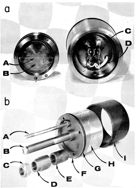
Attempts were made to measure the earth pressures acting on both the flexible and rigid linings. T h e illstruments usecl were vibrating wire earth pressure cells similar to those described by @ien (1958), and were manu- factured and calibrated by Geonor A/S, Oslo, Norway. Figure 4 illustrates the construction of the earth pressure cell. Its dimensions are 4?k in. in diameter by 1% in. high; the diaphragm of the cell is 3% in. in diameter. T h e cells were mounted inside collars welded to the steel liner section, as illustratecl in_ Fig. 5, and positioned as close as possible to the cut surface of the clay.
To ensure that the diaphragm of the cell was in contact with undisturbed clay and to prevent any grout from penetrating between the clay and the dia-
EDEN AND UOZOZUK: OTTA\VA OUTFALL SEWER 21
@ 4 D B M -Deep Bench Mark
3f 1 G M - 3
-
Ground Movement Gauge No. 3FIG. 3. Instrulnentation near station 386+00.
I
q T U N N E L
phragm, thin-walled sharpened steel tubing was fitted inside the collar and the cells were positionecl inside the tube. A back plate was placed over the collar on the inside of the tunnel and used to position a special tool to trim the clay face to conform to the shape of the diaphragm inside the tube. Later, the
*
GM-I GM-2*
3 2 6 - 0 0 D.B.M. 15 0 1 17
3 2 5 + 7 9 @ 16 e 14 0 10 e 3 2 5 + 7 5 ( P I , P 3 8 P 5 on TUNNEL) 13 9!
3 2 5 + 7 1 PLANGM-3 D.B.M. GM-2 GM-I SURFACE (ELEV. 175')
Scale: in f e e t
-
0 5 10 15 2 0 I lo 16 1 14 1 13 1 12 1 1 p 5 v22 CANADIAN GEOTECHNICAL JOURNAL
FIG. 4. Earth pressure cells. ( a ) Interior view of cell. A = Vibrating wire; B = Dia- phragm; C = hjlngnct Assembly; D = Lead wire.
FIG. 4. ( 1 ) ) Cell asscmbly. A = Leacl tube; B = Mounting Post; C = Jamb nut; D = Positioning nut; E = Spacer; F = Flange; G = Sealing ring; H = Cell housing; I = Shelby tube.
EDEN AND BOZOZUK: OTTAWA OUTFALL SEWER 23
FIG. 5. Installation of earth pressure cells. ( a ) Exterior view of cell mounting. A = Cell diaphragm; B = Shelby tube; C = Collar.
( b ) Interior view. A = Lead tube; B = Cell flange.
( c ) Earth pressure cell in place. A = Lead tube; B = Back-up plate.
back plate was used to position the pressure cell. The cell could b e brought to the desired level of prestressing by means of a positioning nut on the back- up plate.
To carry out the installation one complete liner section was obtained from the contractor and brought to the laboratory for fitting. Large removable patches (about 1 ft sq.) were cut out of each segment and collars installed in them. Figure 6 is a vertical section of the liner and indicates the position of the
CELL
24 CANADIAN GEOTECHNICAL JOURNAL
collars. When ii~stallation had been completed, dummy gauges were placed in the collars and the test ring was installed in the tunnel by the contractor.
With the test ring in place and any necessary grouting completed, the installation of the earth pressure cells began. The dummy gauges were removed from the collar and an inspection was made. If necessary, the entire patch could be removed to clear away any grout from the cell area, but this step was not required for any of the cells. The appropriate length of the seamless thin-walled tubing was inserted and pushed from fi to f6 in. into undisturbed clay and fixed in place with a set screw. A trimming tool was inserted in the tube, and using the back plate as a guide the clay face was trimmed. The pressure cell was inserted with the sealing O-ring and flange loosely attached at the back of the cell ( Fig. 4b )
.
The diaphragm of the cell was pushed up to the clay face and the O-ring sealed by tightening the flange. Spacers were then placed on the cell shaft and the back plate was installed. Finally the positioning nut was installed. The reading instrument was hooked to the lead wires and the cell was prestressed to the desired level by tightening the positioning nut, which was held in place with a jamb nut. The level of pre-stress chosen was equivalent to full over- burden pressure.
The lead wires froin each cell were threaded tllrough copper tubing and taken to a junction box on the tunnel roof, where the wires from the eight cells were joined to the members of a 16-concluctor telephone cable. At the first installation, at station 325+75, the conductor cable was encased in a polythene pipe hanging from the tunnel roof and extending back through the airlock to a reading station located in the shaft at station 320+75. The copper tubing and polythene pipe mere required to maintain atmospheric pressure inside the cell housing. The final step was to apply a sealed cover to the junction bos and to protect the back of the cells with a heavy steel mesh.
This installation required nearly 600 ft of lead cable. Difficulties were encountered in obtaining readings in the pressure cells owing to induction along the long unshielcled cable that caused more than one cell to be escitecl during the plucking phase of the reading sequence and resulted in badly scraillbled return signals. Because of the unsatisfactory readings, the test ring was removed and re-installecl at station 376+21 near the east end of the tunnel. There the lead wires were extended to the ground surface by '1 drop hole using
a 1%-in. copper pipe. The total lead length was less than 100 ft, and the difficulties in reading were overcome.
The second installation was made on the flexible liner for only 2 weeks before the concrete lining was placed. The cells remained in operation until April 1965, at which time three became unserviceable ancl the readings were teiminated.
SETTLEMENT OBSERVATIONS
Because of the destruction of the ground-movement gauges, only 3 inontlls of records were obtained. These covered the period of tunnel escavation under the site and hence sllould have been indicative of settlement behavior. At the end of 3 months the following settlements were measured: centerline gauge, 0.23 in.; 25 ft from centerline, 0.1s in.; 50 ft from centerline, not measurable. Because the soil was over-consolidated by about 4 tons per sq. ft the settle- ments should result only froin elastic and recompression settlements brought
EDEN AND BOZOZUK: OTTAWA OUTFALL SEWER 25
about by the change in effective stress. It is believed that the total settlement resulting from the tunnel escavation was very small. For the first 1500 ft the tunnel passed under a housing development and no indications of any signifi- cant settlements have been observed or reported since the tunnel was con- structed.
PIEZOMETRIC OBSERVATIONS
Before construction, piezometric observations had revealed a downward piezometric gradient on the site. This is s11owr1 in Fig. 7 for the early part of 1961 near station 352+00. The tunnel construction had the overall effect of a drain; that is, there was a tendency for water to flow toward the tunnel. Fipure " 8 indicates the effect of tunnel construction for three different situations. No great quantities of water were involved, however, since drainage was never a problem. The tunnel remained as a drainage sink evcn after the con- crete lining had been placed (Fig. 8 ) . Only for a brief period during the spring run-off does the situation chanpe. Durincr these fen7 weeks each vear the " U
piezometric levels rise.
At the start of the tunnel escavation a working air pressure of approsimately 1 atmosphere was maintained for a few days. During this time the upper part of the working face was clay, wit11 a more permeable glacial till in the lower part. The air pressure caused a temporary flow of water away from the tunnel. When the entire working face had extended into clay, the air pressure was dropped to 0.3 kg/cmg, and this slight pressure did not have any marked effect on the piezometric regime. Only those piezometers immediately behind the liner ~ l a t e s L became desaturated.
In summary, the tuunel construction and structure appear to have the net effect of acting as a drainage sink, but because the permeability of the clay is extremely low, the actual movement of water is very slight.
EARTH PRESSURE MEASURElMENTS
The first period of earth pressure measure~nents at station 325+75 cannot be considered sufficiently reliable for quantitative results because of the diffi- culties in reading the instruments with the long lead-in cable. They did, how- ever, indicate that the earth pressure conditions were nearly uniform about the tunnel, averaging about ?A of the full overburden pressure. Measurements on the diameter of the tunnel during this period indicated that the vertical diam- eter decreased with a corresponcling increase in horizontal diameter. The change in diameter was ill the ordcr of 0.1 to 0.2 in. and occurred within 1 month of the installation of the test rings.
In November 1961 pressure cells were re-installed at station 376+21 near the eastern end of the tunnel. Figure 9 indicates the pressure measured on the flexible liner plate 2 weeks after re-installation and coinpares the measurements with the calculated full overburden pressure. Each cell measures the earth pressure in only one small area, so that it is difficult to infer from the readings the distribution of pressure about the cntirc liner ring. The ratio of the average of the individual readings to the calculated overburden pressure was 0.64. The average pressure about the liner was therefore in about the same proportion to the overburden pressure as that in the first installation. Because concreting operations began about 2 weeks after re-installation of the test ring, there was
EDEN AND BOZOZUK: OTTAWA OUTFALL SE\YER
CANADIAN GEOTECHNICAL JOURNAL
DATE: 2 1 ~ 1 1 ~ 6 1 AVE 0;'
-
2.40 KG/CM* AIR PRESSURE: o KG ICM' AVE MEASURED PRESSURE= 1.95 K G / C M ~
FIG. 9. Earth pressure measurements, flexible liner section.
insufficient opportunity to determine any change in the pressure regime with time.
The concrete was placed pneumatically, the steel liner and the pressure cells being subjected to some minor sllocks as the concrete was placed. Read- ings on the earth pressure cells were rather erratic from 30 November to 9 December (see Fig. 1 0 ) . When the concrete began to cure, there was an immediate increase in the pressure measured by the top cell, and some increase recorded by the bottom cell. The top and bottom measurements continued to rise for a period of about 3 months, while the measured average lateral pres- sures remained relatively stable. From kl~larcll 1962 until April 1963 the tunnel was empty and the measured pressures remained nearly static (Fig. 1 0 ) . In April 1963 the tunnel was filled pending a start of operation of the treatment plant. I t remained essentially full for a period of 6 weeks while the plant under- went an operational trial period. With the filling of the tunnel in April, the readings changed very rapidly. The top measured pressure dropped from 2.9 kg/cm2 to 1.2 kg/cm" and the pressure on the bottom cell increased slightly. Presumably this change was due to the sudden increase in weight caused by the filling of the tunnel. When the treatment plant began regular operation the flow in the tunnel dropped to about 25% of capacity and tlle pressure readings tended toward those levels established when the tunnel stood empty. (As the
30 CANADIAN GEOTECHNICAL JOURNAL
tunnel carries both sanitary and storm sewage flow, its normal operation level is much below tunnel capacity. )
In November 1963 the top pressure cell became unserviceable, so that it was no longer possible to monitor the top pressure. Readings were continued on the five remaining serviceable cells until January 1965, when the plant underwent further trials and it was again possible to measure pressures with the tunnel filled to capacity. At this stage readings on the five serviceable cells showed a slight decrease, but not of the same magnitude as was shown during the previous full-load period.
In summary, the measured pressures on the rigid tunnel indicated a higher than anticipated pressure on the top of the tunnel, a lower than expected one on the bottom. Top and bottom pressures averaged about 75% of the calculated full overburden pressure. The lateral pressure remained relatively static at about 0.7 of the average vertical pressure. Because pressures were measured at only eight points, the actual average pressure conditions can only be approxi- mated.
DISCUSSION
Engineering literature contains references to several attempts to measure the pressure on tunnels. Possibly the case most nearly similar to the present study is that of the Detroit water tunnel described by Housel (1943). The Detroit tunnel is about 13 ft outside diameter and was founded 70 ft below the surface in soft, plastic clay. Excavation was by hand methods under air pressure, with a thick reinforced concrete lining closely following excavation. Housel mea- sured pressures on the tunnel with Goldbeck cells from the time of construction in late 1930 until 1941. In time, pressures measured on the bottom of the tunnel exceeded full overburden pressure, pressures measured at the top nearly equalled the overburden pressure, and lateral pressures were about 70% of the full overburden pressure. The pressures on the Detroit tunnel were relatively slow in achieving final equilibrium-some 5 to 6 years.
The Ottawa tunnel has an external diameter of 10 ft and is founded 65 ft below the surface. The Ottawa clay is very stiff and extremely sensitive. Its stress-strain behavior could be described as brittle in contrast with the Detroit clay. Failure in a good unconfined compression test occurs at less than 1% strain. Pressures on the Ottawa tunnel seemed to adjust more quickly than those on the Detroit tunnel. Measurements show that equilibrium is approached in a matter of months. This behavior was indicated when the tunnel was rapidly filled in April 1963 and then emptied in the following month. When the tunnel was filled, the pressure on the top of the tunnel dropped very rapidly, with only a slight increase in the bottom pressure. Presumably the increase in load caused a slight settlement that allowed the clay above the tunnel to mobilize its strength and temporarily relieve some of the pressure on the top of the tunnel. Then as the clay relased as a result of the increased stress levels, the pressure was transferred back to the tunnel. Because of the relatively high deformation modulus of the clay, the required movemeilt to bring about the transfer of stress need only have been very small. The pressure indicated by the top cell
(No. 1) seemed to be reverting to its former level when it ceased to function in December 1963.
In contrast with the Detroit tunnel, the highest pressure of 3.2 kg/cm3 on the Ottawa tunnel was recorded by the top cell, and was slightly higher than the
EDEN AND BOZOZUK: OTTAWA OUTFALL SEWER 31
full overburden pressure. This may have been the result of a local reaction between the soil and the tunnel crown caused by the interaction of the tunnel structure with the surrounding soil.
CONCLUSIONS
Measurements taken in the field to assess the effect of driving a 10-ft diameter tunnel through over-consolidated, extremely sensitive clay led to the following conclusions :
( 1 ) Because of over-consolidation, no appreciable settlement from consolida- tion of the clay was measured at the surface. The clay behaved as a stiff, rela- tively elastic material, and no significant settlements resulted from loss of ground due to readjustments of the clay about the tunnel structure. This was aided by the method of tunnelling and the installation of tight-fitting temporary support.
( 2 ) The tunnel structure appears to have influenced the groundwater regime. The site had a previously existing downward gradient. When the tunnel was completed it continued to act as a drainage sink, although the volume of water drained is probably very small.
( 3 ) The flexible liner plate acted in accordance with previous records of such construction (Ward and Thomas 1965; Terzaghi 1943) in that the vertical diameter decreased with a corresponding increase in lateral diameter. Because of the short time interval for pressure measurements on the flexible liner no definite conclusions can be stated as to the ultimate pressure to be resisted. Approximately two-thirds of full overburden pressure was recorded, with the pressure tending to rise with time.
( 4 ) When the permanent, relatively rigid concrete lining was installed, a difference appeared between the horizontal and vertical pressures on the tunnel. Higher than expected pressures were measured on the crown of the tunnel but, because a reading was taken at one point only, no inference can be made as to whether or not this was an average pressure condition on the crown. At the same time, pressures measured on the tunnel invert were considerably less than overburden pressure. The average of the crown and invert pressure measurements was approximately three-quarters of the full overburden pres- sure. The lateral pressures were about 0.7 of the measured vertical pressures. ( 5 ) It is believed that the earth pressure cells functioned reasonably well, although their useful life was somewhat shorter than desired. Five of the eight cells were still operating after 4 years. Because each cell represents a pressure measurement at one point and because of the rate of attrition, it is recom- mended that future installations double or triple the number of pressure cells. This is especially important for cells measuring vertical and horizontal pres- sures. When the tunnel was filled, the response of the pressure cells to the sudden change in loading indicated that they were satisfactorily sensitive to pressure changes.
* ( 6 ) The Leda clay behaved as a brittle elastic material in spite of its high sensitivity. When loading conditions in the tunnel were suddenly increased durin filling, the clay responded by mobilizing its strength and relieved the tunne
f
of some external pressure. Compared with the Detroit clay, Leda clay reacts more rapidly to pressure changes. The response time appears to be in the order of months rather than years.32 CANADIAN GEOTECHNICAL JOURNAL
ACKNOWLEDGMENTS
The work described in this paper was made possible by the full cooperation of several organizations: the Sewer Branch of the Dept. of Planning and Works of the City of Ottawa; the consulting engineers, Deleuw Cather and Co. of Canada Ltd., particularly Mr. L. J. Marshall and Mr. R. E. Curtis, who were most helpful in making arrangements for the various installations and in keep- ing the Soil Mechanics Section informed of the progress of work; and the contractor, Beaver Construction Co., Limited, especially Mr. John Dow, the Superintendent, to whom special thailks are due for granting the necessary access to the site and for assisting with the actual installations.
This paper is a contribution from the Division of Building Research, National Research Council of Canada, and is published with the approval of the Director of the Division.
REFERENCES
BJERRUM, L. 1956. Letter to Editor. GBotecllnique, 6, ( 3 ) , pp. 157-158.
Bozozm, M. 1968. The spiral-foot settlement gauge. Can. Geotech. J., 5, ( 2 ) , pp. 123- 125.
HOUSEL, W. S. 1943. Earth pressure on tunnels. Proc. Amer. Soc. Civil Engr., 108, pp. 1037-1038.
@LEN, K. 1958. An earth pressure cell for use on short piles, Oslo Subway. Proc. of the Brussels Conference, 1958, on Earth Pressure Problems, 2, pp. 118-126.
TERZAGHI, K. 1943. Liner-plate tunnels on the Chicago subway. Proc. Amer. Soc. Civil. Engr., 108, pp. 970-1007.
WARD, W. H. and T ~ o a r ~ s , H. S. H. 1965. The developnlent of earth loading and deformation in tunnel linings in London clay. Proc. Sixth Intern. Soil Mechanics Conf., Montreal, Canada, 2, pp. 432436.