HAL Id: hal-01009998
https://hal.archives-ouvertes.fr/hal-01009998
Submitted on 19 Jun 2014HAL is a multi-disciplinary open access archive for the deposit and dissemination of sci-entific research documents, whether they are pub-lished or not. The documents may come from teaching and research institutions in France or abroad, or from public or private research centers.
L’archive ouverte pluridisciplinaire HAL, est destinée au dépôt et à la diffusion de documents scientifiques de niveau recherche, publiés ou non, émanant des établissements d’enseignement et de recherche français ou étrangers, des laboratoires publics ou privés.
High Power Impulse Magnetron Sputtering deposition of
Pt inside fuel cell electrodes
Stéphane Cuynet, Amaël Caillard, Thomas Lecas, Jannick Bigarre, Pierrick
Buvat, Pascal Brault
To cite this version:
Stéphane Cuynet, Amaël Caillard, Thomas Lecas, Jannick Bigarre, Pierrick Buvat, et al.. High Power Impulse Magnetron Sputtering deposition of Pt inside fuel cell electrodes. Journal of Physics D: Applied Physics, IOP Publishing, 2014, 47 (27), pp.272001. �hal-01009998�
High Power Impulse Magnetron Sputtering deposition of Pt
inside fuel cell electrodes
S Cuynet1, A Caillard1*, T Lecas1, J Bigarré2, P Buvat2 and P Brault1
1
Groupe de Recherches sur l’Energétique des Milieux Ionisés (GREMI), UMR7344 Université d’Orléans – CNRS BP6744, F-45067 Orléans Cedex 2, France
2
CEA, DAM, Le Ripault, BP16, 37260 Monts, France
* E-mail : [email protected]
Abstract. High Power Impulse Magnetron Sputtering process is used to incorporate
catalytic nanoclusters of platinum into microporous carbon. Such a process leads to an enhancement of the Pt species penetration into the porous media as evidenced by Rutherford backscattering spectroscopy analysis. Each catalyzed porous carbon is tested as a cathode of a proton exchange membrane fuel cell. An increase of 80 % at 0.65 V of the PEMFC power density for a low catalyst loading of 0.02 mg.cm-2 highlights the use of the HiPIMS process versus the conventional DC magnetron sputtering process.
PACS classification codes : 81.15.Cd; 88.30.pd; 82.47.Gh; 52.77.Dq ; 52.40.Hf
Proton exchange membrane fuel cells (PEMFC) have the potential to provide an environmentally friendly engine for transport application. Pure platinum is still the most efficient catalyst even if many attempts have been made to introduce non platinum based materials. The decrease of platinum loading in fuel cell electrodes is one of the main issues for a large scale development of PEMFCs. Several solutions have already been proposed, like the decrease of the platinum particle sizes and the localization of the platinum layer as close as possible to the proton exchange membrane. These can be achieved with physical vapor deposition processes (PVD) as direct current magnetron sputtering (DCMS) [1]. This deposition technique is suitable for the dispersion of ultra-low amount of platinum, but it tends to form a dense overlayer and a decreasing concentration profile into the porous medium [2,3]. The concentration profile is attributed to the interaction of energetic plasma species with the substrate, combined with the hyperthermal kinetic energy of the depositing Pt atoms. Such Pt distribution in the electrode allows high fuel cell electrode efficiency. But the growing Pt overlayer which appears with increasing the Pt amount slows down the Pt transport into the porous medium during the deposition process and limits the power density of the fuel cell [4,5].To avoid the formation of this layer, and to be able to tailor the thickness of the catalyst containing layer, different attempts have been made. For instance the use of an open supporting framework of carbon nanofibers or nanotubes has been investigated [6].This method allows an increase of the Pt catalyst utilization but is extremely difficult to implement and to couple with DCMS. High catalyst utilization efficiency have been obtained by the codeposition of platinum and another material [7], but this was limited to very low amounts of platinum because of the difficulty to deposit porous thin films using DCMS. The present study aims to enhance the Pt transport into the porous medium during the deposition process by using High Power Impulse Magnetron Sputtering (HiPIMS) known to produce ionized and highly energetic sputtered species [8]. In HIPIMS, high power pulses (power densities of several kW.cm-2) with a length of about 100 μs are applied to a conventional planar magnetron, whereas a constant low power (power densities of several W.cm-2) is applied to the target material in DCMS. In HiPIMS, this results in a large fraction of ionized sputtered materials [9]. Anders et al have recently presented a HiPIMS based device able to produce a low divergence ion beam with a limited current density [10, 11]. The high kinetic energy of the sputtered metallic ions allows deep penetration deep into a
substrate [12,13], especially if it’s porous, or when the crystal structure of the substrate is aligned with the flow direction [14]. This kind of device is therefore appropriate in the context of development of PEMFC electrodes made of microporous materials such as gas diffusion layers (GDL).
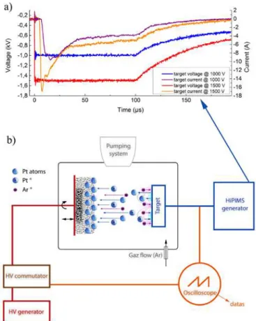
The HiPIMS power source used in the present work is a Hüttinger TPHS 4002. It is characterized by its ability to deliver a maximum voltage of (-)2000 V with a maximum average power of 10 kW. The Pulse duration can reach 200 µs on time with a maximal frequency of 500 Hz. This source is connected to an unbalanced 2" magnetron with a platinum target. A vacuum of 10-7 mbar in the chamber is provided with a serial connection of a primary pump and an Adixen ATH500M turbo-molecular pump. The substrate holder lies in front of the target at a 50 mm distance. The temperature of this substrate holder may be controlled between room temperature (RT) and 700 °C. Rotation during processes ensures thickness homogeneity. An electrical bias may be applied to the substrate. For each deposition run, the argon pressure and flow rate are set to 10-2 mbar and 4 sccm, respectively. For comparative studies, a DC power supply (Advanced Energy Pinnacle Plus) can be used to power the 2” magnetron. Figure 1 displays a schematic of the deposition apparatus. The part (a) of the graph gives the evolution of the voltage and of the current discharge during one HiPIMS pulse. For the pulse voltages of (-)1000 V, a current peak of 10 A appears between 10 and 25 µs and then the current stabilizes down to 3 A (plateau) until the end of the pulse. The measured average power is close to 25 W. For (-)1500 V, the shape of the current curve is similar to the previous one but the maximum and the plateau are close to 16 and 5 A, respectively. This leads to an average power of about 50 W.
Figure 1. Evolution of the voltage and of the current discharge during the HiPIMS on pulse (a) and the schematic of the HiPIMS deposition set up (b).
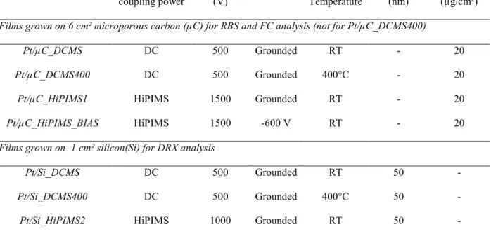
Depositions of Pt catalytic layers was performed for four experimental conditions (specified in table 1) on pieces of silicon 100 (Si) and on microporous carbon substrates (µC), called gas diffusion layer (GDL Sigracet 10BC) through which carbon and hydrophobic polytetrafluoroethylene particles (PTFE) are distributed. PTFE is a major water management component in the gas diffusion layer and it should not be damaged to ensure good performance of the fuel cell. Its melting temperature is around 327 °C [15]. At this temperature and above, the intrinsic properties of PTFE on its support are substantially modified or degraded. In addition to microporous carbon, silicon was used as substrate to study the thermal effect of the HiPIMS process. In DCMS, the voltage was regulated to -500 V, whereas the HiPIMS voltage during the on pulse was set to -1500 V and -1000 V on microporous carbon and on silicon, respectively. The HiPIMS frequency was kept constant to 50 Hz.
Magnetron coupling power Voltage (V) Bias In situ Temperature Thickness (nm) Loading (µg/cm²)
Films grown on 6 cm² microporous carbon (µC) for RBS and FC analysis (not for Pt/µC_DCMS400)
Pt/µC_DCMS DC 500 Grounded RT - 20
Pt/µC_DCMS400 DC 500 Grounded 400°C - 20
Pt/µC_HiPIMS1 HiPIMS 1500 Grounded RT - 20
Pt/µC_HiPIMS_BIAS HiPIMS 1500 -600 V RT - 20
Films grown on 1 cm² silicon(Si) for DRX analysis
Pt/Si_DCMS DC 500 Grounded RT 50 -
Pt/Si_DCMS400 DC 500 Grounded 400°C 50 -
Pt/Si_HiPIMS2 HiPIMS 1000 Grounded RT 50 -
Table 1. Description of the sputtered catalyst depositions on microporous carbon (µC) and/or on silicon (Si).
Rutherford Backscattering Spectroscopy (RBS) is used to measure the total Pt content of the µC substrate (the Pt content measured by profilometer for Si substrate) and to qualify the Pt penetration into the gas diffusion layer (1 cm²). The kinetic energy of the 4He particles and the scattering angle are fixed to 2 MeV and 165°, respectively. The sputtering time is adjusted to obtain a Pt loading of 20 µg.cm-2 on each µC substrate. Structural properties of the Pt deposition on silicon are determined using a X-ray diffraction in θ/2θ configuration. Finally, a set of three coated GDL electrodes are tested in real fuel cell conditions on the cathode side. These 5 cm2 electrodes are assembled with a non-prehumidified Nafion® NRE211 polymer electrolyte and an anode type Sigracet 10BC, previously covered by 20 µg.cm-2 of platinum by conventional DCMS process carried out in the same deposition set up. Each asymmetric membrane electrode assembly (MEA) is mechanically pressed at 2 Nm torque between two bipolar plates without hot pressing. Oxygen and hydrogen gases are introduced in the PEMFC fuel cell without humidification. A homemade procedure is done to ensure a quick and an efficient use of the MEAs.
During the three first hours of operation, voltage pulses between 0.35 V and 0.8 V at 1 Hz are applied on the fuel cell and the delivered current density is recorded on a PC. During the three hours, the
temperature and the absolute backpressure are modified. A temperature of 30 °C and a backpressure of 1.1 bars are applied during the first half hour, 30 °C/2 bars are then applied during one hour (between 0:30 and 1:30) and 50 °C/2 bars is applied during the last one and a half hours. Once the pulsed mode is finished, the backpressure and temperature are increased to 3 bars and 70 °C and the polarization curves (cell voltage E vs current density j) are registered one hour later.
First of all, the four 20 µgPt.cm−2 deposits grown on microporous carbon, Pt/µC_DCMS,
Pt/µC_DCMS400, Pt/µC_HiPIMS2 and Pt/µC_HiPIMS_BIAS, were characterized by RBS.
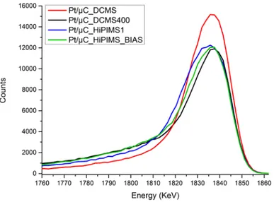
Figure 2. Rutherford Backscattering Spectroscopy spectrum between 1760 and 1860 keV (corresponding to the platinum peak) of the four Pt depositions on microporous carbon (GDL 10BC Sigracet®). The Pt loadings corresponding to the areas under the four peaks were measured (20 µgPt.cm-2 for each). The kinetic energy of the 4He particles and the scattering angle are fixed to 2 MeV and 165°, respectively.
The figure 2 displays a zoom on the Pt peak detection area ranging from 1760 keV to 1860 keV. The low energy tails of all the spectra (below 1820 keV) corresponds to the Pt incorporated inside the microporous carbon, whereas the values between 1820 and 1860 keV are representative of a Pt overlayer at the outermost GDL surface. The intensity of the Pt/µC_DCMS peak reaches a maximum at 1500 counts, which is much higher than the values obtained for the three other spectra. Moreover,
the low energy tail is below that of the other spectra. These two findings show that there is more platinum in the overlayer for the Pt/µC_DCMS sample than for the three others deposits and that the amount of Pt which has diffused inside the micropous media is lower. From the other RBS spectra, it also appears that DCMS deposition performed at 400 °C and the use of the HiPIMS power supply (with or without a substrate bias) decreases the amount of Pt atoms in the overlayer to the benefit of the Pt penetration inside the microporous substrate. Moreover, it seems that this trend is furthered when a negative bias is applied to the substrate during the HiPIMS process. From this first observation, it can be deduced that this enhanced penetration using HiPIMS may be either thermal- or kinetic-assisted. The HiPIMS regime may induce a temperature rise of the substrate due to the interaction of the high energy plasma species or due to the infra-red radiation emitted the target surface that is heated during the sputtering process [16]. Even if a previous study from Lundin et al [17] has shown that HiPIMS discharge induces less substrate heating than a DCMS discharge, we performed XRD to study the Pt catalyst deposited on silicon which tends to form PtSi phases at high temperature.
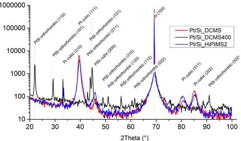
Figure 3. X-ray diffractogram (in θ/2θ configuration) of three Pt depositions on silicon between 20 and 100°.
Structural analyses were performed on the three samples, Pt/Si_DCMS, Pt/Si_DCMS400 and
Pt/Si_HiPIMS1. If the structure of the Pt/Si_HiPIMS deposited film is similar to the Pt/Si_DCMS400
techniques. XRD spectra are presented in figure 3. Formation of PtSi phases are evidenced when the deposition temperature is 400 °C in DCMS, but not when HiPIMS power supply is used. The platinum silicide formation on silicon has already been studied in the past [18,19] and can occur above 200 °C. Thus the absence of silicide on the HiPIMS deposit shows that the temperature remains quite low and that the diffusion process is not driven by a thermal effect.
The three deposits on GDL, Pt/µC_DCMS, Pt/µC_HiPIMS2, Pt/µC_HiPIMS_BIAS, are used as cathodes for testing in three asymmetric membrane electrode assembly (MEA). The deposition performed in DCMS at 400 °C has not been tested because of the damages expected to be induced on the GDL by heating. Figure 4(a) displays the three first hours of fuel cell operating. At the beginning, the current delivered at 0.35 V by the MEA containing the Pt/µC_HiPIMS_BIAS is the highest.
Pt/µC_DCMS based MEA exhibits a higher current than the Pt/µC_HiPIMS2 one. During the second
and the third hour, the current delivered by both HiPIMS based MEA increases and gives the highest values. Nevertheless, measurements reveal a lower current at 0.8 V for cathodes prepared by HiPIMS (called HiPIMS cathodes) than for DCMS one and the two open circuit voltages (OCV) of the HiPIMS MEAs are about 30 mV below that of the DCMS MEA. These two last results may be explained by low Pt content in the overlayer for each HiPIMS cathode, which means less catalyst lies in direct contact with the electrolytic membrane.
Figure 4. (a) Current delivered by three MEA during the first three operating hours. These three MEAs correspond to the DC MEA (red), non-biased HiPIMS MEA (blue) and biased HiPIMS MEA (green). The electronic charge is pulsed (frequency 1 Hz, duty cycle 50%, low level 0.35 V). (b) Cell voltage E vs current density j and power density P vs current density j for the three tested MEAs. The dashed lines show the range values of the power density at a cell voltage of 0.65 V. The cell temperature and the gas backpressure are 70°C and 3 bars; respectively. Experimental conditions: Nafion NRE212, three identical anodes prepared by the deposition of 20 µgPtcm-2 by DCMS on GDL Sigracet 10BC.
The figure 4(b) displays the polarization curves of the three MEAs after the pulsed mode. Over all the current densities, the HiPIMS cathodes lead to the highest voltage, especially when a bias is applied on the substrate. The curves of the DC (red) and the non-biased HiPIMS (blue) based MEAs appear almost similar above 400 mA.cm-2, but the HiPIMS MEAs (blue) leads to higher performance below 400 mA.cm-2. A current increase of 35% (between the red and blue curves) is observed at 0.65 V, typical voltage value used in industrial fuel cell for transportation. The power densities delivered by the three MEAs at this voltage are between 110 and 200 mW.cm-2 as shown by the dashed horizontal lines on the figure. These power densities are 110, 150 and 200 mW.cm-2 for the three MEA :
Pt/µC_DCMS, Pt/µC_HiPIMS2, Pt/µC_HiPIMS_BIAS, respectively. This reveals a high Pt activity for
both HiPIMS cathodes, especially for the Pt/µC_HiPIMS_BIAS one. Here all the fuel cell cathodes contain the same amount of catalyst, but the dispersion inside the micro-porous layer is different. The
slopes of the three curves (corresponding to the humidified membrane conductivity) are quite similar. This indicates that the membrane conductivity is not affected by the HiPIMS deposition of catalyst at the membrane/cathode interface. Moreover, no current drop is observed at high current density for the HiPIMS based MEAs which indicates that no water flooding occurs in the electrode. The hydrophobic properties of the electrode are not decreased, which means that the PTFE is not damaged during the HiPIMS process. This confirms the XRD analysis.
In conclusion, this study reveals how HiPIMS may be a powerful technique to embed catalyst in a porous media used as electrode support in PEMFC. Such a process leads to an enhancement of the Pt species penetration into the porous media as detected by Rutherford backscattering spectroscopy. By improving its penetration, the deliverable current density is improved. In the present testing conditions and in the activation part of the E(j) curve (about 0.65 V), the power density is 80 % higher for a cathode prepared by HiPIMS coupling to a substrate bias than for a cathode prepared by DCMS. Because of the enhanced Pt penetration in the porous support, the Pt amount may be slightly increased (over 20 µg.cm-2) without the formation of a dense Pt overlayer (limiting the Pt penetration). These results demonstrate the ability to significantly improve the cell performances of MEAs.
Acknowledgements
This work has been supported by the CNRS and the ANR (Emergence AMADEUS). Maud JULLIEN, Thierry SAUVAGE and Blandine COURTOIS are acknowledged for XRD and RBS analyses. We are grateful for the useful advice and suggestion from Christophe COUTANCEAU and Anne-Lise THOMANN. We would like to thank Thomas LECAS and Sébastien DOZIAS for precious technical help.
References 1
Brault P, Caillard A and Thomann A-L 2011 Polymer Electrolyte Fuel Cell Electrodes Grown by Vapor Deposition Techniques Chemical Vapor Deposition 17 296–304
2
diffusion of platinum nanoparticles in porous carbon assisted by plasma sputtering Surface and
Coatings Technology 200 391–4
3
Brault P, Josserand C, Bauchire J-M, Caillard A, Charles C and Boswell R W 2009 Anomalous diffusion mediated by atom deposition into a porous substrate Physical Review Letters 102
4
Gruber D, Ponath N, Müller J and Lindstaedt F 2005 Sputter-deposited ultra-low catalyst loadings for PEM fuel cells Journal of Power Sources 150 67–72
5
Caillard A, Charles C, Ramdutt D, Boswell R and Brault P 2009 Effect of Nafion and platinum content in a catalyst layer processed in a radio frequency helicon plasma system J. Phys. D: Appl.
Phys. 42 045207
6
Caillard A, Charles C, Boswell R, Brault P and Coutanceau C 2007 Plasma based platinum nanoaggregates deposited on carbon nanofibers improve fuel cell efficiency Applied Physics Letters 90 223119
7
Cavarroc M, Ennadjaoui A, Mougenot M, Brault P, Escalier R, Tessier Y, Durand J, Roualdes S, Sauvage T and Coutanceau C 2009 Performance of plasma sputtered fuel cell electrodes with ultra-low Pt loadings Electrochemistry Communications 11 859–61
8
Bohlmark J, Lattemann M, Gudmundsson J T, Ehiasarian A P, Aranda Gonzalvo Y, Brenning N and Helmersson U 2006 The ion energy distributions and ion flux composition from a high power impulse magnetron sputtering discharge Thin Solid Films 515 1522–1526
9
Sarakinos K, Alami J and Konstantinidis S 2010 High power pulsed magnetron sputtering: A review on scientific and engineering state of the art Surface and Coatings Technology 204 1661–84
10
Oks E and Anders A 2010 A self-sputtering ion source: A new approach to quiescent metal ion beams Review of Scientific Instruments 81 02B306
11
Bohlmark J, Östbye M, Lattemann M, Ljungcrantz H, Rosell T and Helmersson U 2006 Guiding the deposition flux in an ionized magnetron discharge Thin Solid Films 515 1928–31
12
Anders A 2010 High power impulse magnetron sputtering and related discharges: Scalable plasma sources for plasma-based ion implantation and deposition Surface and Coatings Technology 204 2864–8
13
quantum dots embedded in SiO2 matrix synthesized by plasma immersion ion implantation
Nanotechnology 22 285605
14
Alami J, Persson P O A, Music D, Gudmundsson J T, Bohlmark J and Helmersson U 2005 Ion-assisted physical vapor deposition for enhanced film properties on nonflat surfaces Journal of Vacuum
Science & Technology A 23 278–80
15
Oshima A, Tabata Y, Kudoh H and Seguchi T 1995 Radiation induced crosslinking of polytetrafluoroethylene Radiation Physics and Chemistry 45 269–73
16
Cormier P A, Thomann A L, Dolique V, Balhamri A, Dussart R, Semmara N, Lecas T, Brault P, Snyders R and Konstantinidis S 2013 IR emission from the target during plasma magnetron sputter deposition Thin Solid Films 545, 44-49
17
Lundin D, Stahl M, Kersten H and Helmersson U 2009 Energy flux measurements in high power impulse magnetron sputtering J. Phys. D: Appl. Phys. 42 185202
18
Poate J M and Tisone T C 2003 Kinetics and mechanism of platinum silicide formation on silicon
Applied Physics Letters 24 391–3
19
Faber E J, Wolters R A M and Schmitz J 2011 On the kinetics of platinum silicide formation