HAL Id: hal-03140275
https://hal.archives-ouvertes.fr/hal-03140275
Preprint submitted on 12 Feb 2021HAL is a multi-disciplinary open access archive for the deposit and dissemination of sci-entific research documents, whether they are pub-lished or not. The documents may come from teaching and research institutions in France or abroad, or from public or private research centers.
L’archive ouverte pluridisciplinaire HAL, est destinée au dépôt et à la diffusion de documents scientifiques de niveau recherche, publiés ou non, émanant des établissements d’enseignement et de recherche français ou étrangers, des laboratoires publics ou privés.
Design of a transparent co-and counter-rotating
eccentric Couette cell dedicated to study the interfacial
flow behavior of viscous fluids under free surface shear
Prashanth Thirunavukkarasu, Romain Castellani, Celine Cohen, Francis
Fournier, Edith Peuvrel-Disdier, Arnaud Pignolet, Rudy Valette, Bruno
Vergnes
To cite this version:
Prashanth Thirunavukkarasu, Romain Castellani, Celine Cohen, Francis Fournier, Edith Peuvrel-Disdier, et al.. Design of a transparent co-and counter-rotating eccentric Couette cell dedicated to study the interfacial flow behavior of viscous fluids under free surface shear. 2021. �hal-03140275�
1
Design of a transparent co- and counter-rotating eccentric Couette cell
dedicated to study the interfacial flow behavior of viscous fluids under free
surface shear
Prashanth THIRUNAVUKKARASU1,2, Romain CASTELLANI1, Céline COHEN3, Francis FOURNIER1, Edith PEUVREL-DISDIER1*, Arnaud PIGNOLET1, Rudy VALETTE1, Bruno VERGNES1.
1 MINES ParisTech, PSL Research University, CEMEF – Centre de Mise en Forme des Matériaux, UMR
CNRS 7635, CS 10207, 06904 Sophia-Antipolis, France.
2 Manufacture Française des Pneumatiques Michelin – Ladoux, 63118 Cébazat, France.
3 Université Côte d’Azur, CNRS UMR 7010, Institut de Physique de Nice, Parc Valrose, 06108 Nice,
France.
* Corresponding author : Edith PEUVREL-DISDIER, edith.disdier@mines-paristech.fr
Abstract
In the present work, a prototype was developed to observe the flow behavior of viscous fluids (103 to 105 Pa.s) under free surface shear. The geometry of the prototype is an eccentric Couette cell where both cylinders can rotate in the same or opposite directions. Transparent windows permit in-situ observations during flow. The design, development and testing of the prototype with a viscous model fluid are reported in this paper. In order to obtain information on contact lines and free surfaces under shear, the flow behaviour of a small fluid volume was investigated in co- and counter-rotating conditions. The different flow
conditions and information that can be obtained are described. A particular attention is paid to determine steady state flow conditions.
2
1. Introduction
Interfacial flows can concern three different interfaces: the flow at solid/fluid interfaces, dealing with slip and no slip boundary conditions, the flow at solid/fluid/air interfaces, dealing with the dynamics of contact lines, and the flow along the fluid/air interfaces or free surfaces. The present work aims at investigating the dynamics of contact lines and the shape of free surfaces in the case of high viscosity fluids submitted to a shear flow. For sake of simplicity, in this case, the flow at the solid/fluid interface should satisfy the no slip boundary condition.
Studying the dynamics of contact lines (started in the 1920s [1-6]) has remained an open research area (see e.g. [7-10]) since the motion of contact lines is a ubiquitous situation encountered in nature and
technological applications (e.g. sticking of rain drops) and many industrial processes in relation with wetting and spreading phenomena (surface coating, painting…). First studies were conducted on the motion of contact lines of a fluid under capillary pressure and the motion of a droplet over a solid substrate. This situation appeared to be complex from a physico-chemical point of view, due to the necessity of a multiscale description of the fluid at the contact line (see e.g. [7, 11, 12]). From a mechanical point of view, the motion of the contact line over a solid surface violates the no slip boundary condition and leads to a stress
singularity at the contact line [10, 13, 14]. Most of the works were conducted in the case of simple liquids and low viscosity fluids where the surface tension plays a role in the force balance at the interface. The situation in the case of a viscous fluid is different because the flow is dominated by viscous forces (surface tension negligible) with potential viscous dissipation phenomena.
The motion of contact lines in viscous fluids is often encountered in polymer processing. Understanding the complex flow in order to give a proper thermomechanical description of the processing conditions started in the second half of the 20th century and implied direct observations through the introduction of tools with transparent walls. For example, interfacial flows were investigated in transparent dies with different geometries at the exit of extruders to understand and determine slip conditions, flow regimes, and flow instabilities [15-16]. Transparent walls in injection moulding allowed to observe the kinematics of the fountain flow during the filling process [17]. The fountain flow indeed shows the motion of the front free surface but in a shear flow driven by the pressure (Poiseuille flow). Front transparent walls were also introduced in internal mixers to observe the mixing process (in particular the distribution process) of highly viscous polymers, and to identify zones of stagnation depending on the rotor geometry [18-22]. During these experiments, the free surfaces of the fluid could be observed because the fill factor was about 0.75.
However, these observations were complex as three dimensional and transient in nature, due to the continual transfer of fluid from one mixing chamber to the other and the geometry of the rotors.
Simplified flow conditions were used to investigate the efficiency of the rotor geometry by using a single rotor rotating in a transparent cylindric chamber [23]. Simple flow geometries such as transparent Couette cells (including eccentric ones) were also used to investigate the kinematics of distributive mixing [24-26].
3
This flow geometry was also extensively studied to understand the journal bearing flow [25]. These observations were conducted on model fluids (room temperature, low viscosity less than 10 Pa.s) and on a fully filled chamber which did not allow the observation of free surfaces nor contact lines.
The behaviour of fluid/gas interfaces could be investigated with off-centred Couette cells when a small volume is introduced in the thin gap zone between the cylinders. This flow configuration was used to simulate the coating process of a solid substrate by a fluid in roll coating applications and to investigate printer’s instabilities which develop at the interface [27-29].
The present work reports on the design and development of a transparent eccentric Couette cell where both cylinders can be rotated independently but dedicated to high viscosity fluids (103 to 105 Pa.s). The objective is to investigate the flow behaviour of small fluid volumes in the thin gap region between the cylinders, by observing free surfaces and contact lines in steady state conditions. This paper reports on first observations with the prototype with a high viscosity silicone fluid, at room temperature, in co- and counter-rotating conditions. This first step aimed at determining steady state flow configurations favourable to observe the interfacial flow behaviour at the contact lines and free surfaces.
2. Description of the prototype
2.1. Principle of the experiments
The eccentric Couette cell was chosen for the localized zone of high shear rate around the thin gap region. The fluid motion is induced by the rotation of the two cylinders, driven by independent motors allowing their rotation in both directions. The counter-rotating mode is depicted in Figure 1. We focussed our attention on small fluid volumes to observe free surfaces and contact lines in the thin gap region, where the flow is simple and well defined. Two cases were considered as of interest in the present work (Figure 1): - a first volume, noted Vinf, enabling the fluid to be in direct contact with both cylinders. This
configuration allows us to follow the dynamics of 4 contact lines (indicated by letters A, B, C and D) and 2 free surfaces (surfaces AB and CD). Within the directions of rotation of the cylinders in Figure 1.a, A and C are receding lines, whereas B and D are advancing lines;
- a larger volume, noted Vsup thereafter, allowing to form a uniform layer of fluid along the outer cylinder
and to have an excess fluid volume recirculating in the upstream region of the thin gap between the two cylinders. In this case, the excess fluid volume is in contact on one side with the inner cylinder and on the other side with a fluid layer of the same fluid. Here, only one contact line with the metallic cylinder (contact line with the inner cylinder indicated as A) and one free surface are observed (see Figure 1.b).
Insert Figure 1
4
The Couette cell was designed to work with high viscosity fluids (as high as 105 Pa.s, typical viscosity range
of uncured elastomers) and to be temperature controlled up to 100°C. To work at a controlled temperature with high viscosity fluids with cylinders rotating in both directions and transparent windows constitutes the originality of the present geometry. A global view of the Couette cell and auxiliary elements is shown in Figure 2. The device is constituted by:
- the transparent Couette cell with the motors, - a heating system including thermal baths,
- a joystick to manually pilot the cylinders, coupled with a computer interface to drive the motors and record the parameters,
- an imaging system composed of lightening and recording systems. Insert Figure 2
The mechanical part of the device ensuring the fluid motion (Couette cell and motors) is shown in Figure 3. Insert Figure 3
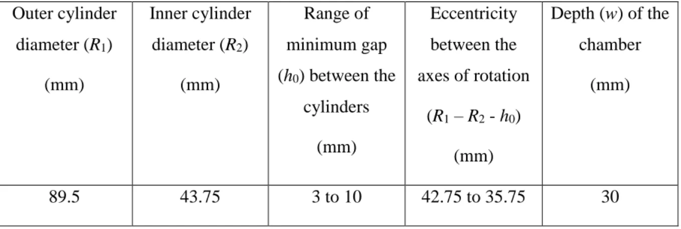
The dimensions of the Couette cell are indicated in Table 1. The outer cylinder radius (R2 = 89.5 mm) was
chosen to have a large enough zone of observation in the thin gap region. The radii of the outer and inner cylinder were chosen to have a ratio of 2:1. The gap h0 can be varied in a certain range (3 to 10 mm). Its
minimum value was chosen to enable flow observations in this zone. The inner and outer cylinders radii and the gap h0 define the eccentricity between the axes of rotation of the cylinders. The depth of the chamber w
(equal to the length of the cylinders) was initially chosen to be large enough relatively to h0 (w/h0 = 10 for
the smallest gap) in order to minimize the side effect due to the transparent windows and to have a 2D flow [30]. A similar geometry was developed by Rabaud et al. [27], but for room temperature low viscosity fluids. If the diameters of the cylinders are quite similar, their length is fully different : 200 mm for low viscosity fluids compared to 30 mm in our case. The introduction and shearing of a high viscosity fluid on a long cylinder (even for a fluid volume limited to the thin gap region) would not be possible because of the torque necessary for the motors. The present Couette cell depth is representative of the chamber depth in laboratory internal mixers dedicated to mix high viscosity fluids.
Insert Table 1
The Couette cell is constituted by the inner and outer cylinders, the transparent windows and the motors. The main elements of the prototype are described in the following.
The outer cylinder consists of an annular surface (drawn in red on Figure 4.a) made of 42Cd4 steel which is welded onto a gear wheel (Figure 4). The gear wheel is set in rotation by the motor (motor axis shown in Figure 4b). The rotational axes of the inner and outer cylinders were chosen to be horizontal to facilitate observations. As the influence of gravity on the flow of highly viscous fluids is negligible, this does not impact the flow behaviour.
5
The outer cylinder surface is welded onto a groove machined in the gear part. The circulation of the heat transfer fluid through this groove ensures the heating of the outer cylinder surface.
The gear wheel and the outer cylinder surface are enclosed within two outside metallic walls (green parts in Figure 3).
Insert Figure 4
The inner cylinder is presented in Figure 5. It is composed of a hollow cylinder with a shaft (depicted in green) driven by a motor. The surface of the inner cylinder (depicted in red) is heated by a closed circuit of heat transfer fluid. The shaft is equipped with inlet and outlet valves for the heat transfer liquid to enter and exit this hollow space. A perforated plate (depicted in brown) is used to force the heat transfer fluid to the surface of the inner cylinder.
Insert Figure 5
Contrarily to the outer cylinder surface, the inner cylinder surface is removable, in order to be able to tune its nature (composition, roughness, etc.). In the present work, inner and outer cylinder surfaces were similar (made of 42Cd4 steel with same roughness).
A small gap was left on purpose between the flat sides of the inner cylinder and the transparent windows to prevent any friction due to the contact between the rotating surfaces. Unfortunately, the fluid tends to enter this gap during the rotation of the cylinders and can generate a substantial torque on the motor. Therefore, O-rings were designed and introduced into grooves on both sides of the inner cylinder (Figure 5) to limit the friction between the surfaces and prevent the fluid infiltration in this gap. They are held in position on the window surface thanks to springs.
Observations of the fluid flow are made by light transmission through two transparent windows. They are made of annealed borosilicate glass to resist stresses generated by the fluid flow at temperatures up to 100°C. The front window is circular. Because of the rotation axis of the inner cylinder, the rear window is annular. The central part is constituted by a stationary metallic part which includes a double eccentric (Figure 3). The stationary metallic part is fixed to the metallic frame of the outer cylinder. The double eccentric ensures the fixation of the inner cylinder rotation axis relatively to the outer cylinder one. It also allows to tune its position relatively to the outer cylinder and is crucial to fix the minimal gap h0.
Transparent windows are fixed on both side of the rotating gear wheel of the outer cylinder thanks to annular clamps and screws (Figure 4). They thus rotate at the same velocity as the outer cylinder.
The introduction of the fluid and the cleaning are achieved by dis- and re-assembling the front window. The inner and outer cylinders are heated by circulation of a heat transfer fluid connected to two
independent thermal baths. The heat transfer fluid is a commercial silicone oil, sold as Julabo™ 8940114 (Julabo, Seelbach, Germany).
6
Observations are performed and recorded with a Panasonic G80 camera equipped with an Olympus
M.Zuiko lens (30 mm f / 3.5 Macro) placed on a tripod. The observation zone is illuminated via two lamps placed on each side of the prototype.
The rotation of the cylinders is ensured by independent brushless motors (MDP enterprise, Neyron, France). The maximum torque provided by the motors is 100 Nm and 50 Nm for the outer and inner cylinder,
respectively. The rotational speeds of the inner and outer cylinder were limited to 16 and 3.2 rpm,
respectively, to have a precise control of the speed. Shear rates up to 35 s-1 can be obtained in the in counter-rotating condition.
A LabView program was created as an interface to display and record the different variables measured by the different sensors. The rotational speeds and directions of the cylinders are imposed and controlled with a joystick (Figure 2). The torque is measured on each motor axis via 100 mm lever arms and stress gauges. Two thermocouples are placed in hollow spaces of both cylinders to control the temperature of the heat transfer fluid. The measured temperatures are considered as the temperatures of the cylinder surfaces. A third thermocouple can be inserted in a hole through the front window to measure the temperature of the fluid at the end of the experiment.
The different information collected by the sensors are displayed on a personal computer by the LabView program and recorded as a function of time.
The device allows to vary the following parameters: - the fluid used,
- the volume of fluid introduced,
- the rotation directions of the cylinders, - their speed,
- the minimum gap h0,
- the temperature, nature (limited to the inner cylinder surface) and roughness of the inner and outer cylinder surfaces, with the possibility to have asymmetric conditions of contact with the fluid, - the nature of the transparent window.
In this paper, only the fluid volume, the direction and velocities of the cylinders are varied, all the other parameters being fixed.
2.3. Limitations due to the flow geometry
Some limitations were identified while working with the prototype:
- 105 Pa.s was found to be the upper limit of the fluid viscosity that can be sheared in the thin gap region.
7
- Despite the presence of specific brass O-rings in the inner cylinder, a small quantity of fluid can escape and be trapped in the thin gap between the inner cylinder side and the front transparent window.
- The fluid also tends to stagnate along the frontier between the immobile metallic support (double eccentric) of the inner cylinder axis and the moving parts of the prototype (rear transparent window and inner cylinder surface). This results in a low but continual loss of fluid during the experiment. - Despite routine cleaning of the prototype, negligible amounts of impurities get trapped around the stagnation points. This is the reason why a transparent fluid becomes non-transparent after a short period of time under shear.
- The fluid flow is not purely 2D but rather 3D. Indeed, the fluid motion is not only induced by the rotation of the inner and outer cylinders but also by the rotation of the transparent windows (same rotation as the outer cylinders). However, the observation of the flow across the transparent windows only permits a 2D description.
3. Results and discussion
3.1. Fluid characteristics
Preliminary experiments were conducted to define the suitable characteristics of the fluid used for the study of the stabilization in position under flow in counter-rotating conditions of a small fluid volume. These steady state conditions (defined in terms of cylinder velocities) will be referred as stabilization conditions in the following. For this type of experiment, the fluid should satisfy the following properties:
- Incompressibility: if the fluid presents some compressibility (linked to the presence of air bubbles for example), it is not possible to find reproducible stabilization conditions.
- Non-evolutive properties with time: indeed, any evolution of the fluid properties would affect stabilization conditions,
- Fluid viscosity range: 103 ≤ 0 ≤ 105 Pa.s. The lower viscosity limit is linked to the effect of gravity
for large volume in the upstream flow where the gap enlarges. The upper limit is linked to the motor power and the stiffness of the Couette cell.
- Viscoelastic character: some elasticity should help to stabilize the fluid shape within these shear flow conditions.
- No gel-like behaviour: gels and highly crosslinked fluids irreversibly break as they pass through the thin gap region.
- No slip condition with the cylinder surfaces: in case of wall slip on the cylinders in the counter-rotating mode, the fluid would experience no shear.
8
- Adhesion with the solid walls: in order to have 2D kinematics (no effect of the glass walls), the fluid should present a lower adhesion relatively to the glass walls compared to the cylinder surfaces. The ideal situation would be that the fluid is only dragged by the cylinder walls, with no effect of the glass walls.
Following these recommendations, a transparent high viscosity silicone fluid was selected. It is referred as “Liquid Glass Thinking Putty®” (Crazy Aaron, Nebraska, USA [31]) and obeys a Carreau-Yasuda
behaviour, characterized by a Newtonian viscosity of 2.2 104 Pa.s. Flow experiments were only conducted at room temperature in the present work. The fluid rheological behaviour is shown in Figure A in the S.I. section. It was checked that the rheological behaviour of the fluid at the beginning (transparent fluid) and at the end (presence of impurities leading to a non-transparent fluid) of the experiment was similar.
3.2 Determination of the fluid volumes of interest
Fluid volumes of interest (see Figure 1) are determined based on geometrical considerations.
The large fluid volume Vsup (Figure 1.b) corresponds to volumes larger than the volume necessary to form a
uniform layer of thickness h0 around the outer cylinder (Vh0 = 8.7% of the free volume of the Couette cell).
The small fluid volume Vinf (Figure 1.a) is by definition lower than Vh0. It is in practice limited to 4.5% in
order that the fluid volume is restricted in the converging zone.
The objective is to determine flow configurations in which contact lines and free surfaces can be observed at fixed locations relatively to the laboratory framework. For this reason, the first step of the work was to scan the different flow conditions playing with the fluid volume, the direction of rotation of the cylinders and their velocities, enabling to determine steady state conditions. The velocities mentioned in this part refer to the linear velocities of the surface of each cylinder. The different flow configurations are reported in the sections 3.3 to 3.5.
3.3 Rotation of a single cylinder
The fluid volume is introduced in the shape of a “ball”.
If one of the cylinders (for example, the outer cylinder) is put into rotation, the fluid is dragged by the rotating cylinder. It is driven through the converging zone between the cylinders, where it is sheared and squeezed. Once the fluid passes through the thin gap region, it is not deformed anymore. It is simply carried out by the rotating cylinder. If the fluid volume is large enough (Vsup condition), a uniform layer is deposited
9
at the same speed V1 as the outer cylinder surface and the transparent windows. The exact thickness of the
film should depend on the viscoelastic behaviour of the fluid and the maximum shear rate driving the
relaxation process. In the case of the silicone fluid, the flow behaviour is dominated by the viscous character and no relaxation effect on the macroscopic thickness of the film was observed. The length of the deposited layer is thus fixed by the minimum gap and the introduced volume.
3.4 Co-rotation conditions
After a fluid volume is introduced, the velocity of the outer cylinder is first imposed at a fixed value and the one of the inner cylinder is progressively increased. Then the speed of the outer cylinder is increased and so on.
In the case of a small fluid volume (Vinf), no steady state observations can be obtained (Figure 6). The
situation is very similar to the previous case of a single rotating cylinder: the fluid is deformed as it passes through the converging flow channel, what results in the formation of a film of uniform thickness on the outer cylinder surface, whose thickness corresponds to the thin flow gap h0.
Insert Figure 6
On the contrary, the flow of large fluid volumes (Vsup) always leads to a stationary situation, whatever the
cylinder velocities are (Figure 7). As for the small volume, the passage of the fluid in the thin gap region first leads to the formation of a uniform layer, up to the moment when the layer is present all around the outer cylinder. The flow geometry does not enable to drag the excess of volume. This leads to the formation of a recirculating fluid reservoir (ovoid shape) as it is observed in some coating processes [27] or in
calendering [30]. The flow in the converging zone leads to a pressure built up [30]. However, with the present geometry (cylinder diameters, eccentricity) and the cylinders relative velocities, the maximum pressure is quite small. The recirculating volume is controlled by the introduced volume, the minimal gap and the relative cylinders velocities.
Insert Figure 7
3.5 Counter-rotating conditions
In the case of a small fluid volume (Vinf), when increasing the inner cylinder velocity (V2), at a fixed outer
cylinder velocity (V1), three types of flow conditions can be observed:
- When the inner cylinder velocity is small compared to the outer cylinder one (‖𝑉2‖ < ‖𝑉1‖), it is impossible to stabilize the fluid. The fluid is displaced in the rotation direction of the outer cylinder until it is split into two blocks at the exit of the thin gap region (Figure 8.a),
10
- In an optimal range of inner cylinder velocity, the fluid can be stabilized between the two cylinder surfaces (Figure 8.b), permitting steady state observations,
- At excessive inner cylinder velocity ((‖𝑉2‖ >> ‖𝑉1‖), the fluid is displaced by the inner cylinder surface till it loses contact with the outer cylinder surface (Figure 8.c). At the end, the fluid volume takes a cylindric shape as it is displaced away from the thin gap region. At this position, the fluid rotates as a solid body between the inner and outer cylinder surfaces. It should be noted that the flow is transitory in nature at this position since it is easily destabilized by any variation of fluid volume (reintroduction of trapped fluid) or contact surface with the transparent windows (scratches on the windows).
Optimal conditions of stabilization were found to be at velocities corresponding to ‖𝑉2‖ > ‖𝑉1‖. The inner cylinder is required to rotate at a higher linear velocity to overcome the drag flow provided by the rotating outer cylinder and the transparent windows. Once the optimal inner cylinder velocity is found, the fluid is stabilized in its current position. It should be noted that the fluid volume can be stabilized at different positions in the converging zone even for the same velocities condition. As the shape of the fluid volume is highly dependent on its position in the flow channel, this means that some information as the location of the contact lines, and the solid/fluid contact surfaces are mainly defined by the fluid volume and its position in the converging zone.
While working with a large fluid volume, a uniform layer is first created on the outer cylinder surface. Although in counter-rotating mode, there is always a recirculating fluid volume in addition to Vh0. This
volume is mainly fixed by the initial fluid volume and the minimum gap h0 within the investigated range of
velocities. Two flow conditions can be distinguished for the recirculating volume depending on the inner cylinder velocity (V1 being fixed):
- Up to a critical value V2 crit (V2 < V2 crit), the recirculating fluid volume (ovoid shape, Figure 9.a) is
stabilized at the thin gap region. Steady state observations are possible when the inner cylinder velocity (V2) does not dominate the flow of the outer cylinder velocity (V1), i.e. at velocities up to a
critical value V2 crit > V1.
- At high inner cylinder velocities (V2 >> V1), the recirculating fluid volume gets separated from the
uniform layer and progressively dragged away by the inner cylinder from the thin gap region (Figure 9.b). As for the small fluid volume at high V2, the fluid volume in excess ends up as a cylinder
rotating between the inner cylinder and the uniform deposited layer. Insert Figure 9
3.6 Example of observations
11
- the 2D profile of the fluid volume under shear can be obtained by image analysis. An example is illustrated in Figure 10 in the case of a counter-rotating condition. From such a profile, it is possible in particular to identify the shape of the free surfaces ([AB] and [CD] in figure 1.a)),
- the velocity field or streamlines illustrating the internal fluid motion can be visualized at the
beginning of the experiment when the silicone fluid is still transparent. The addition of tracers helps this visualization.
4 Conclusions
The characterization of the interfacial flow behaviour of viscous fluids remains an open topic. Experimental observations of the interfacial flow are important to understand this behaviour, especially for high viscosity fluids. A transparent eccentric Couette cell, enabling the rotation of the inner and outer cylinders in both directions, was designed and developed to characterize the flow of small volumes of high viscosity fluids under controlled shear with free surfaces.
The prototype provides transient and steady state flow observations by controlling the direction and speed of rotation of the cylinders. Various viscous fluids were tested. The required properties of the fluid for steady state observations in counter-rotating conditions were identified. A high viscosity silicone fluid was chosen to carry out first flow observations at ambient temperature.
The flow behaviour of the silicone fluid was investigated while varying the direction of rotation of the cylinders (co- or counter-rotation), the speed of the inner and outer cylinders, and the introduced fluid volume.
Different flow conditions allowing to stabilize the fluid volume in the converging zone were identified: - for a small fluid volume, the whole volume could be stabilized in the counter-rotating mode for a
defined balance of the inner and outer cylinders velocities,
- for a larger volume with a continuous uniform layer of fluid on the outer cylinder, the recirculating fluid volume could be stabilized whatever the cylinders velocities in the co-rotating mode and under critical velocity conditions in the counter-rotating mode.
The developed prototype also allows to characterize the interfacial flow via the observation of the free surfaces (fluid/gas interfaces), the position of the contact lines, the interfacial contact area between the fluid and the cylinders, in both steady state and transient conditions. The prototype allows these observations while varying:
- the nature of the fluid,
- the rheological behaviour of the fluid, - the volume of fluid introduced,
12
- the velocities of the cylinders,
- the rotation directions of the cylinders, - the minimal gap h0,
- the temperature of the inner and outer cylinder surfaces, - the roughness of the inner and outer cylinder surfaces, - the nature of the inner cylinder surface.
The objective of this step was to determine steady state flow configurations favourable to investigate the interfacial flow behaviour. The next step will be to better analyse the steady state behaviour in the counter-rotating mode and investigate if steady state conditions could be used to determine an adhesion energy contribution in the case of a high viscosity fluid under free surface shear conditions.
Acknowledgements
The authors wish to thank the members of the MEA team of CEMEF (Marc Bouyssou, Eric Brotons, Christelle Combeaud, Guillaume Corvec) for their involvement in the manufacturing of the different components of the machine.
This manuscript is in honor of the 50 year anniversary of the French Polymer Group (Groupe Français des Polymères - GFP).
Funding:
This study was carried out within the framework of the OSUM project, FUI AAP23, funded by BPiFrance. Prashanth Thirunavukkarasu’s PhD is funded by Michelin MFP. Special thanks are addressed to Bruno Dratz and Pascal Tremblay from Michelin for their initiative, involvement and discussions during this work.
References
[1] G. D. West, On the resistance to the motion of a thread of mercury in a glass tube, Proc. Roy. Soc. A 86 (1911) 20-25
[2] R. Lucas, Über das Zeitgesetz des kapillaren Aufstiegs von Flüssigkeiten, Koll.-Z. 23 (1918) 15-22. [3] E.W. Washburn, The dynamics of capillary flow, Phys. Rev. 17 (3) (1921) 273-283.
[4] E.K. Rideal, On the flow of liquids under capillary pressure, Phil. Mag. 44 (1922) 1152-.
[5] R.N. Wenzel, Resistance of solid surfaces to wetting by water, Ind. Eng. Chem. 28 (1936) 988−994. [6] A.B.D. Cassie, S. Baxter, S. Wettability of porous surfaces, Trans. Faraday Soc. ,40 (1940) 546−551
13
[7] G. Lu, X.D. Wang, Y.Y. Duan, A critical review of dynamic wetting by complex fluids: from Newtonian fluids to non-Newtonian fluids and nanofluids, Adv. Colloid Interface Sci. 236 (2016) 43–62,
https://doi.org/10.1016/j.cis.2016.07.004
[8] T.A. Terhemen; Y.S. Gbaoron, Contact angle hysteresis – Advantages and disadvantages: A critical review, Rev. Adhes. Adhes. 8 (2020) 47-67, https://doi.org/10.7569/RAA.2020.097302
[9] B. Andreotti, J.H. Snoeijer, Statics and dynamics of soft wetting, Ann. Rev. Fluid Mech. 52 (2020) 285-308, https://doi-org.insis.bib.cnrs.fr/10.1146/annurev-fluid-010719-060147
[10] N.T. Chamakos, D.G. Sema, A.G. Papathanasiou, Progress in modeling wetting phenomena on structured substrates. Arch. Comput. Meth. Eng. (2020), https://doi.org/10.1007/s11831-020-09431-3 [11] P.G. de Gennes, Wetting: statics and dynamics, Rev. Mod. Phys. 57(3) (1985) 827-863,
https://doi.org/10.1103/RevModPhys.57.827
[12] D. Bonn, J. Eggers, J. Indekeu, J. Meunier, E. Rolley, Wetting and spreading, Rev. Mod. Phys. 81 (2009) 739-805, https://doi.org/10.1103/RevModPhys.81.739
[13] C. Huh, L.E. Scriven, Hydrodynamic model of steady movement of a solid / liquid / fluid contact line, J. Colloid Interf. Sci. 35 (1971) 85-101, https://doi.org/10.1016/0021-9797(71)90188-3
[14] M.C.T. Wilson, J.L. Summers, Y.D. Shikhmurzaev, A. Clarke, T.D. Blake, Non-local hydrodynamic influence on the dynamic contact angle: Slip models vs experiment, Phys. Rev. E, 73(4) (2006) 041606,
https://doi.org/10.1103/PhysRevE.73.041606
[15] L. Robert, Y. Demay, B. Vergnes, Stick-slip flow of high density polyethylene in a transparent slit die investigated by laser Doppler velocimetry, Rheol. Acta 43 (2004) 89-98,
[16] C. Combeaud, B. Vergnes, A. Merten, D. Hertel, H. Münstedt, Volume defects during extrusion of polystyrene investigated by flow induced birefringence and laser-Doppler velocimetry, J. Non-Newt. Fluid Mech. 145 (2007) 69-77,
[17] H. Yokoi, Part IV: Process visualization, control, optimization, and simulation: Internal visualization of mold cavity and heating cylinder, in Injection Molding, Technology and Fundamentals, edited by M.R. Kamal, A. Isayev and S.-J. Liu, Carl Hanser Verlag, Munich 2009, 395-438,
https://doi.org/10.3139/9783446433731
[18] P.K. Freakley, W.Y. Wan Idris, Visualization of flow during the processing of rubber in an internal mixer, Rubber Chem. Technol. 52 (1979) 134-145.
[19] T. Asai, T. Fukui, K. Inoue, M. Kuriyama, Proc. International Rubber Conference Paper III-4, Paris (1983).
14
[20] K. Min, J.L. White, Flow visualization of the motions of elastomers and molten plastics in an internal mixer, Rubber Chem. Technol. 58 (1985) 1024-1037, https://doi.org/10.5254/1.3536098
[21] J.L. White, K. Min, C.Y. Ma, R. Brzoskowski, Basic studies of flow visualization of processing of elastomers and their compounds : Internal mixer and extrusion, J. Polym. Eng. 6 (1986) 79-93
[22] K. Min, Flow visualization parallel and perpendicular to the rotor axes for elastomers and molten plastics in an internal mixer - The influence of rotor design, Intern. Polym. Proc. 1 (1987), p. 179-187,
https://doi.org/10.3139/217.870179
[23] O. Breuer, H. Chen, B. Lin, U. Sundararaj, Simulation and visualization of flow in a new miniature mixer for multiphase polymer systems, J. Appl. Polym. Sci. 97 (2005) 136–142,
https://doi.org/10.1002/app.20998
[24] J. Chaiken, R. Chevray, M. Tabor, Q. M. Tan, Experimental study of Lagrangian turbulence in a Stokes flow, Proc. Roy. Soc. A 408 (1986) 165-174, https://www.jstor.org/stable/2398145
[25] K.H. de Haas, D. van den Ende, C. Blom, E.G. Altena, G.J. Beukema, J. Mellema: A counter-rotating Couette apparatus to study deformation of a sub-millimeter sized particle in shear flow. Rev. Scient. Instr. 69 (3) (1998) 1391-1397. https://doi.org/10.1063/1.1148771
[26] J.F. Agassant, A. Poitou, R. Valette, A kinematic approach to distributive mixing in Mixing and Compounding of Polymers, 2nd edition, edited by I. Manas Zloczower, Carl Hanser Hanser, Munich (2009)
217-240
[27] M. Rabaud, S. Michalland, Y. Couder, Dynamical regimes of directional viscous fingering: Spatiotemporal chaos and wave propagation, Phys. Rev. Lett. 64 (1990) 184-189,
https://doi.org/10.1103/PhysRevLett.64.184
[28] L. Pan, J.R. de Bruyn, Spatially uniform travelling cellular patterns at a driven interface, Phys. Rev. E 49 (1994) 483-493, https://doi.org/10.1103/PhysRevE.49.483
[29] F. Varela Lópeza, L. Paucharda, M. Rosenb, M. Rabaud, Non-Newtonian effects on ribbing instability threshold, J. Non-Newt. Fluid Mech. 103 (2002) 123–139
[30] J.F. Agassant, P. Avenas, P.J. Carreau, B. Vergnes, M. Vincent, Polymer Processing - Principle and Modelling, Carl Hanser Verlag, Munich, 2017, https://doi.org/10.3139/9781569906064
[31] M.A. Minuto, Method of making bouncing silicone putty like compositions, Patent US 4,371,493 (1983)
15 Outer cylinder diameter (R1) (mm) Inner cylinder diameter (R2) (mm) Range of minimum gap (h0) between the cylinders (mm) Eccentricity between the axes of rotation (R1 – R2 - h0) (mm) Depth (w) of the chamber (mm) 89.5 43.75 3 to 10 42.75 to 35.75 30
16
Figure captions
Figure 1 – Schematic representation of the flow geometries of interest for (a) a small volume of fluid Vinf
and (b) a large volume Vsup, illustrated in the case of the counter-rotating mode
Figure 2 – Couette cell and auxiliary systems: 1. computer interface control, 2. observation zone, 3. heat
transfert fluid connections with the two thermobaths, 4. and 6. power control, 5. joystick to drive the cylinder rotation direction and the velocities
Figure 3 – Computer-aided design of the mechanical part of the Couette cell: (a) front view, (b) rear view.
1. Clamp fixing the transparent windows, 2. outer cylinder surface, 3. double eccentric setting the inner cylinder position, 4. annular transparent rear window, 5. inner cylinder surface, 6. zone of observation, 7. inner cylinder rotation axis, 8. Inner cylinder motor, 9. Outer cylinder motor, 10. torque sensor on the outer cylinder.
Figure 4 – Computer-aided design of the outer cylinder part: (a) with the outer cylinder surface (welded
surface represented in red), (b) represented in the device (welded surface withdrawn to show the heat transfer fluid circulation). 1. Fixation points for the drive gear, 2. fixation points of the outer annular seal fixing the front window, 3. inlet and outlet canals of the heat transfer fluid circulation, 4. heat transfer fluid circulation in contact with the outer cylinder surface, 5. welded outer cylinder surface, 6. drive gear, 7. motor axis.
Figure 5 – Computer-aided design of the inner cylinder: 1. spring joints between the inner cylinder and the
window, 2. inner cylinder surface, 3. rotation axis, 4. heat transfer fluid circulation, 5. perforated plate to force the heat transfer fluid along the inner cylinder surface.
Figure 6 – Transient flow observations under co-rotation condition with a small fluid volume at two
different times.
Figure 7 – Flow observations under co-rotation condition with a large fluid volume,
Figure 8 – Flow observations under counter-rotating condition with a small fluid volume: (a) insufficient
inner cylinder velocity, (b) optimal inner cylinder velocity for stabilization, (c) excess inner cylinder velocity.
Figure 9 – Flow observations under counter-rotating condition with a large fluid volume: (a) at a sufficient
inner cylinder velocity, (b) at an excess inner cylinder velocity.
Figure 10 – (a) Image analysis of the 2D profile of the fluid volume, (b) Observation of streamlines in the
17
Figure 1
18
Figure 3
Figure 4
19
Figure 6
20
21
Figure 9