HAL Id: hal-02014480
https://hal.archives-ouvertes.fr/hal-02014480
Submitted on 15 Feb 2019
HAL is a multi-disciplinary open access
archive for the deposit and dissemination of
sci-entific research documents, whether they are
pub-lished or not. The documents may come from
teaching and research institutions in France or
abroad, or from public or private research centers.
L’archive ouverte pluridisciplinaire HAL, est
destinée au dépôt et à la diffusion de documents
scientifiques de niveau recherche, publiés ou non,
émanant des établissements d’enseignement et de
recherche français ou étrangers, des laboratoires
publics ou privés.
Copyright
Light-induced self-organization in cold atomic clouds
Guillaume Labeyrie, Robin Kaiser
To cite this version:
Guillaume Labeyrie, Robin Kaiser. Light-induced self-organization in cold atomic clouds.
Univer-sité Côte d’Azur Complex Days, M. Argentina; S. Barland; P. Reynaud-Bouret; F. Cauneau; K.
Guillouzouic; U. Kuhl; T. Passot; F. Planchon, Jan 2018, Nice, France. pp.117-121. �hal-02014480�
Light-induced self-organization
in cold atomic clouds
Guillaume Labeyrie and Robin KaiserAbstract Patterns are ubiquitous in nature and have been extensively stud-ied in biology, chemistry and physics including optics. We report here on ex-periments where pattern formation occurs in a cloud of laser cooled atoms. We identify three different mechanisms allowing spatial patterns to sponta-neously emerge in either the atomic density, the excited state population, or the atomic spin state.
1 Experimental setup for self-organization in cold atoms
The typical setup used in these experiments in shown in 1. We prepare a cloud of cold87Rb atoms in a magneto-optical trap (MOT) using large di-ameter trapping laser beams. The produced cloud is cold (≈100 µK), with a diameter larger than 1 cm, and contains up to 1011 atoms. The optical den-sity for light resonant with the atomic transition is large, typically 100. The ability to produce such large clouds is an important prerequisite to realize these experiments. Once the cloud is prepared, we release it from the trap by shutting down both MOT beams and magnetic field gradient. Shortly af-ter release, the cloud is illuminated by a linearly-polarized, pulsed ”pump” laser beam (pulse duration 1 ms to 1 ms) of waist 2 mm, which is frequency
Guillaume Labeyrie
Institut de Physique de Nice (INPHYNI), 06560 Valbonne, France e-mail:guillaume. [email protected]
Robin Kaiser
Institut de Physique de Nice (INPHYNI), 06560 Valbonne, France e-mail: robin. [email protected]
118 Guillaume Labeyrie and Robin Kaiser VC 23 mm l/4 PBS s -NF FF FF NF CC M PB s +
Fig. 1 Experimental setup for pattern observation. VC: vacuum chamber. CC: cold cloud. PB: pump beam. M: mirror. l/4: quarter-wave plate. PBS: polarizing beam-splitter.
detuned from the atomic transition by δ (positive or negative). We use de-tunings larger than the atomic linewidth Γ (typically|δ/Γ| ≈10) such that
most of the pump beam is transmitted by the cloud. This transmitted beam is then retro-reflected by a mirror located at a distance d behind the cloud.
The cloud behaves as an optical medium with a nonlinear index of refrac-tion. If a small fluctuation of this index occurs in the plane transverse to the beam propagation axis, a small phase fluctuation is imprinted on the trans-mitted beam. After propagation in free space over 2d, this phase fluctuation turns into an intensity fluctuation due to diffraction. This intensity fluctua-tion reacts on the nonlinear index of the cloud (optical feedback), and leads to a spontaneous oscillation in the transverse plane above a certain intensity threshold. Thus, one observes the appearance of a spatially modulated light intensity distribution in the transverse plane, with an underlying spatially modulated atomic susceptibility. We observe these light patterns by imaging the beam’s transverse cross-section at a distance 2d after the cloud, using the small amount of light transmitted by the mirror as shown in 1. The field distributions can be recorded simultaneously in near-field (NF) and far-field (FF).
2 Different mechanisms for self-organization
In the course of this work, we observed different modes of self-organization depending on the experimental parameters. We demonstrated the existence of three distinct nonlinear mechanisms relying on different atomic degrees of freedom. In the following, we briefly describe these various mechanisms and the associated patterns.
3 m
m
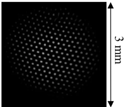
Fig. 2 Example of optomechanical patterns.
2.1 Optomechanical self-organization
This type of self-organization is observed for positive detunings, relatively low pump intensities (50 mW/cm2) and pump pulse durations larger than 100 µs. It relies on the dipole force exerted by the spatially modulated light on the cold atoms. Given sufficient time, the atoms spatially bunch into the potential wells, yielding a modulated index of refraction. Because the effi-ciency of this bunching process depends on the kinetic energy of the atoms, the intensity threshold for pattern formation depends of the temperature of the cloud in this situation. We show in2an example of self-organization in this case, where a nice hexagonal long range order is observed [1].
2.2 ”Electronic” self-organization
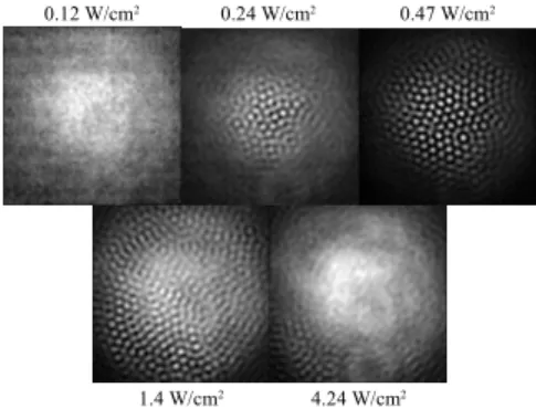
To observe this type of self-organization we employ positive detunings as well, but higher pump beam intensities (above 200 mW/cm2) and much shorter probe pulses (≈1 µs). In such a short time, the cold atoms cannot move over significant distances. Instead, the nonlinearity relies here on the saturation of the (quasi-2 level) atomic transition, which occurs when a sig-nificant amount of the population is transferred to the excited state. This is quantified by the so-called saturation parameter s= (I/Isat)/[1+4.(δ/Γ)]2.
In this expression I is the pump laser intensity and Isatan atomic parameter (here Isat=3.6 mW/cm2). For s 1 the index of refraction is linear, for s≈1 the index is Kerr-like and for s 1 the index saturates to 1. The observations reported in3are in agreement with this behavior. At low pump intensity
(be-120 Guillaume Labeyrie and Robin Kaiser
0.12 W/cm2 0.24 W/cm2 0.47 W/cm2
1.4 W/cm2 4.24 W/cm2
Fig. 3 Behavior of electronic patterns versus pump intensity.
low threshold) nothing occurs, then upon increasing I patterns appear and develop, and disappear again at high intensities due to the saturation of the index of refraction [2].
2.3 Spin self-organization
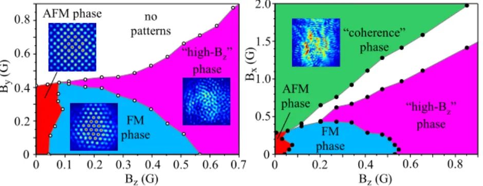
This regime of self-organization is drastically different from the two previ-ous ones. It requires a negative detuning, and an accurate cancellation of residual magnetic fields. Once this is achieved, we apply a weak (≈ 1 G) magnetic field B of controlled magnitude and direction, and observe the complex phase space shown in4.
For B≈0, we observe structures with a square symmetry. The comparison of the images in the two circular polarization channels show that this is an anti-ferromagnetic state (AFM), with alternating domains with spin-up and spin-down atoms with equal populations [3,4]. Increasing the longitudinal magnetic field Bz breaks the symmetry between s+ and s−and results in a ferro-magnetic phase (FM) of hexagonal symmetry, where one spin orienta-tion dominates. A further increase of Bzresults in a different phase (”high-Bz phase”), without long range order but with local hexagonal symmetry.
We also observe strikingly different behaviors versus transverse magnetic field. When the transverse magnetic field By(orthogonal to the input polar-ization) is increased, all patterns vanish. To the contrary, when Bx(parallel to the input polarization) is increased, a new phase (”coherence phase”) arises, without long-range order and with a peculiar symmetry. Both experimen-tal observations and numerical simulations indicate that this phase is linked
“coherence” phase AFM phase By ( G ) Bz (G) no patterns FM phase “high-Bz” phase 0 FM phase 0.1 0.2 0.3 0.4 0.5 0.6 0.7 0 0.2 0.4 0.6 0.8 AFM phase Bz (G) 0 0.2 0.4 0.6 0.8 Bx ( G ) 0.5 1.0 1.5 2.0 0 “high-Bz” phase
Fig. 4 Magnetic phase-space of spin patterns. Bxis the transverse component of the
mag-netic field parallel to the input polarization, Bythe transverse component of the magnetic
field orthogonal to the input polarization, and Bzthe component of the magnetic field
along the pump beam propagation.
to the presence of a spatially-modulated coherence between ground states induced by the s+/s−fields [4].
References
1. Labeyrie G., Tesio E., Gomes P.M., Oppo G.-L., Firth W.J., Robb G.R.M., Arnold A.S., Kaiser R., and Ackemann T., Optomechanical self-structuring in a cold atomic gas, Nature Photonics 8, 321 (2014).
2. Camara A., Kaiser R., Labeyrie G., Firth W.J., Oppo G.-L., Robb G.R.M., Arnold A.S., and Ackemann T., Optical pattern formation with a 2-level nonlinearity, Phys. Rev. A
92, 013820 (2015).
3. Kresic I., Labeyrie G., Robb G.R.M., Oppo G.-L., Gomes P.M., Griffin, Kaiser R., and Ackemann T., Spontaneous light-mediated magnetism in cold atoms, Communica-tions Physics 1, 33 (2018)
4. Labeyrie G., Kresic I., Robb G.R.M., Oppo G.-L., Kaiser R., and Ackemann T., Mag-netic Phase Diagram of Light-mediated Spin Structuring in Cold Atoms, Optica 5, 1322 (2018).