HAL Id: hal-01664659
https://hal.inria.fr/hal-01664659
Submitted on 19 Dec 2017
HAL is a multi-disciplinary open access
archive for the deposit and dissemination of
sci-entific research documents, whether they are
pub-lished or not. The documents may come from
teaching and research institutions in France or
abroad, or from public or private research centers.
L’archive ouverte pluridisciplinaire HAL, est
destinée au dépôt et à la diffusion de documents
scientifiques de niveau recherche, publiés ou non,
émanant des établissements d’enseignement et de
recherche français ou étrangers, des laboratoires
publics ou privés.
Stride detection for pedestrian trajectory
reconstruction: a machine learning approach based on
geometric patterns
Frédéric Chazal, Bertrand Beaufils, Marc Grelet, Bertrand Michel
To cite this version:
Frédéric Chazal, Bertrand Beaufils, Marc Grelet, Bertrand Michel. Stride detection for pedestrian
trajectory reconstruction: a machine learning approach based on geometric patterns. IPIN 2017 - 8th
International Conference on Indoor Positioning and Indoor Navigation, Sep 2017, Sapporo, Japan.
pp.1-6, �10.1109/IPIN.2017.8115867�. �hal-01664659�
Stride detection for pedestrian trajectory
reconstruction: a machine learning approach based
on geometric patterns
Bertrand Beaufils
⇤, Frédéric Chazal
†, Marc Grelet
‡and Bertrand Michel
§ ⇤‡Sysnav, 57 Rue de Montigny, 27200 Vernon, France⇤†§ Inria Saclay team DataShape, 1 Rue Honoré d’Estienne d’Orves, 91120 Palaiseau, France § Centrale Nantes Informatic and Mathematics Department, 1 Rue de La Noe, 44300 Nantes, France
Email: ⇤[email protected],†[email protected], ‡[email protected],§[email protected]
Abstract—In this paper, a strides detection algorithm is pro-posed using inertial sensors worn on the ankle. This innovative approach based on geometric patterns can detect both normal walking strides and atypical strides such as small steps, side steps and backward walking that existing methods struggle to detect. It is also robust in critical situations, when for example the wearer is sitting and moving the ankle, while most algorithms in the literature would wrongly detect strides.
I. INTRODUCTION
The emergence of GPS in the 2000s has changed the perception of navigation. It has become usual to be positioned in everyday life. However in practice no system exists for pedestrian positioning that works in any environment. Indeed positioning and navigation using GPS quickly reaches some limitations due to poor reception in many situations, for exam-ple in tunnels, indoor parking, in the forest, inside buildings etc.
In this context, Sysnav developed systems based on magneto-inertial sensors [1], [2], to enable trajectory recon-struction. Here we consider an ankle worn device for dead reckoning. This system has the advantage of not requiring any complementary infrastructure contrary to map matching, Wi-Fi [3], Radio Frequency Identification [4] or ultra-wideband [5].
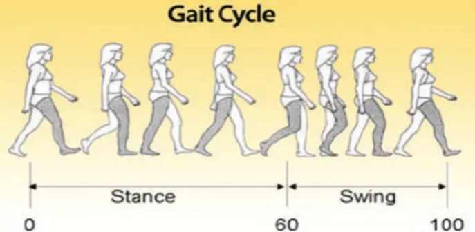
The strategy which consists in the integration of the accel-erations and speeds to compute a trajectory rapidly cumulates large errors. To overcome this issue we use a technique inspired by Zero Velocity Update (ZUPT) [6], [7], [8], [9], which is an effective method to limit the accumulation of errors. It consists in correcting the speed drift by estimating the speed of the ankle when the foot is on the ground during the walk and then integrates the data only between two ZUPTs. This technique therefore requires to detect precisely when a stride occurs and its two different phases: stance and swing (Figure 1).
Several studies [10], [11], propose to detect pedestrian movements and classify activities (such as walking, stairs climbing, running...) from inertial data. Theses approaches do
Fig. 1: Gait cycle (www.optogait.com).
not work well outside a controlled environment [12]. Moreover these methods based on sliding windows do not allow to detect individual strides. A few methods of stance detection have been proposed in the literature by tuning thresholds to determine the start and the end of the phases [13], [14], [15], or using machine learning techniques on the frequency char-acteristics of the signals [16], [17]. These methods show good results when it is known that the pedestrian is walking but fail in a lot of real life situations. Indeed, several foot movements in sitting position for example are wrongly detected as strides. In this work we describe our step detector which is built on a machine learning algorithm and the innovative modeling of the swing phase. The same approach can also be applied to recognize the activity of the performed step. Activity recognition can be a valuable information in many situations, for example in medical context, but we focus here on trajectory reconstruction.
II. SENSORS ALIGNMENT
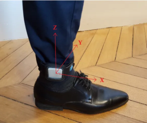
The system is worn around the ankle as shown in the Figure
2. The method presented in this paper requires the sensors orientation to be the same for each wearer. By definition, the z axis is aligned with the leg and the x axis is aligned with the foot. However the device may be upside down and may turn around the ankle.
SUBMITTED
Version
!
PUBLISHED
VERSION
AVAILABLE
IN
IPIN
2017
PROC
.Fig. 2: Body frame definition.
To address this issue, we have to compute the rotation that aligns the sensors on the orientation defined Figure2. Several strides were recorded for seven activities (backward walking, left and right side stepping, walking, running, climbing and descending stairs), ensuring that the system was placed as defined in Figure 2. From these records, the gyroscope data was used to define a reference pattern (in three dimensions) for each activity. The goal is to fit the gyroscope data of a new stride to each reference pattern by allowing a rotation.
Since the calculation method is the same for the seven 3D reference patterns, we will not indicate the activity in the following Section. Let Y = (Y1. . . Yn) with Yi 2 R3 the 3D reference pattern data of size n on the three gyroscope axes and (X1. . . XN) the gyroscope data of a new stride. The first step is to bring the observed data to the same number of samples as the reference pattern by a cubic spline interpolation [18] on each axis. Let X = (X1. . . Xn)be the vector of the observations. We want to compute the rotation R that minimizes Pn
i=1!i||RXi Yi||22. The coefficients !1, . . . , !n are the weights given to the samples of the stride (Pn
i=1!i= 1). We can for example give more weight to the samples in the middle of the stride compared to those in the end. Typically the foot movement on the ground during the stance phase is less specific to the activity than during the swing phase.
Property 1. — Given Xi 2 R3 and Yi 2 R3 for all i in [[1, n]]. The solution of the problem
R⇤= argmin RRt=I,det(R)=1 n X i=1 !i||RXi Yi||22, is given by R⇤ = V Ut, (1) where V and U are the unitary matrices of the decomposition into singular values of XW Yt, and W = diag(!
1, . . . , !n) withPn
i=1!i= 1.
We compute this rotation matrix for the seven 3D reference patterns to be sure that at least one good alignment has been computed. In the rest of the paper we assume that the rotated data of the stride are in the reference frame defined in Figure
2.
III. SWING MODELLING
We saw (Figure1) that the cycle of a stride is divided into two phases: swing and stance. During the swing phase, moving the foot forward creates a distinctive pattern in the y axis of the gyroscope (Figure 3). In this paper we call forward swing the sequence where the values remain negative. The
Fig. 3: Forward swing.
aim of this Section is to model the forward swing. We want to compute a 1D reference pattern that defines the gyroscope data on the y axis of the forward swing for six activities we have chosen empirically: slow walking, normal walking, fast walking, running, climbing and descending stairs. Several strides were recorded for each activity and tagged with a label kcorresponding to the activity (TableI).
Activity Label k Slow walking 1 Normal walking 2 Fast walking 3 Running 4 Climbing stairs 10 Descending stairs -10 TABLE I: Label definitions.
Let Nk the number of strides of each activity k. We note fl,k the observed function associated to the gyroscope data on the y axis of the lth on N
k forward swing of the activity k and fk the unknown function associated to the reference pattern of the activity k, defined on the interval [0, 1] in R. We assume that the 1D reference pattern we want to compute can be approached with an error ✏lby all the fl,kfunctions of
the same activity by multiplying them with a real coefficient al,k
fk= al,k⇥ fl,k+ ✏l,k. (2) We assume that the functions belong to a function space E with its norm ||.||. The observations are the functions fl,kand we want to compute the estimators ˆfk and ˆal,k which are computed by least squares minimization under constraints (P) for all k dans {1, 2, 3, 4, 10, 10} and for all l dans J1, NkK:
ˆ fk = argmin fk2E,||fk||=1 X l ||ˆal,kfl,k fk||, (3) ˆ al,k = argmin al,k2R⇤+ ||al,kfl,k fˆk||. (4)
To solve the problem (P), we consider an orthonormal basis (e1, . . . , ep) for the norm ||.||. In practice, we use Lagrange polynomials [19] but other basis can be selected such as Fourier basis. We note:
ˆ fk = p X u=1 ˆueu, (5) fl,k = p X u=1 ↵l,ueu. (6)
Property 2. — Given ⇤l= (↵l,1, . . . , ↵l,p)tand the symet-ric matrix A defined by Aij =Pl↵||⇤l,i↵l,j
l||22 , the solution of
the problem (P) is given by: ˆ fk=± p X u=1 !p,ueu, (7) and ˆ al,k= Pp u=1↵l,uˆu Pp u=1↵2l,u , (8)
where !p is the eigenvector of A associated to its greater eigenvalue.
As the forward swing is defined by negative values, we choose in practice the solution of Equation 7 that takes negative values. The functions ˆfk are computed once for all. We can now extract the forward swing of a new stride (negative values of the y axis gyroscope data), compute the multiplier coefficient (Equation 8) using ˆfk coefficients and compare it to the 1D reference patterns.
IV. ALGORITHM
A. Preprocessing
The first step of the algorithm is to select intervals of potential strides in the inertial data. The contact of the foot with the ground is detected with a peak in the acceleration norm. A combination of criteria on the acceleration norm (close to one g) and angular velocity norm (local minimum) is used to define the start and the end of the stride. The threshold values have to be sufficiently wide to detect all types of strides (small steps, running, stairs etc.). However many intervals are
wrongly selected when the wearer is moving its ankle but not walking. The goal is now to select among these intervals which ones are true strides. We adopt a statistical learning approach to answer this problem.
A group of people of various ages and heights, were filmed practicing several activities while wearing the system. From the intervals selection above, a learning set is built using video control. A binary label is affected to each interval indicating if it is a stride or not. Our database contains about 6000 positive intervals and also about 6000 negative intervals. In this binary classification problem, we adopt a strategy of supervised machine learning algorithm.
B. Features engineering process
1) Frequency domain: From the norm of both accelerom-eter and gyroscope, features were computed in the time and frequency domains: maximum, mean, standard deviation, root mean square, interquartile range, Fast Fourier Transform...
2) Alignment: Using the alignment correction computed in Section II, the rotated gyroscope data of the interval is compared to the 3D reference pattern of each activity: Pn
i=1!i||RXi Yi||22. Features are computed from the resid-uals during the stance and swing phases.
3) Swing: If the interval is a stride, at least one rotation transforms the data so that the extracted forward swing phase is visible on the y axis of the gyroscope (Figure 3). This forward swing is compared to the six 1D reference patterns ˆfk (Equation7) with the corresponding coefficient ˆal,k(Equation
8): ||ˆal,kfl,k fˆk|| for k taking values in {1, 2, 3, 4, 10, 10} (TableI). The residuals are used as features.
C. Gradient Boosting Tree algorithm
Following the strategy explained in Section III.B for each element of our database, 2695 features are computed. We want to build a binary classifier that decides if one interval is a stride. Several supervised statistical learning algorithms have been tested notably random forests which are known to perform well in large dimensions, Support Vector Machine (SVM), LASSO regression and boosting algorithms such as Adaboost and GBT (Gradient Boosting Tree [20]). We evalu-ated their performance using the cross-validation method (10-fold cross-validation [21]). The chosen algorithm with the best results is GBT.
The principle of boosting is to iteratively focus on ob-servations that are difficult to predict. For the GBT algo-rithm, the general idea is to compute a series of (very weak) decision trees [22] and to aggregate the results to minimize a cost function. Let fn be the prediction function at the iteration n which is the weighted sum of n trees fn = !1nT ree1+ . . . + !nnT reen. We compute a new tree T reen+1which minimizes the cost function on fn+1 defined by fn+1= !n+11 T ree1+ . . . + !nn+1T reen+ !n+1n+1T reen+1. The computed trees remain unchanged during the iterations whereas the wheights are updated at each step.
D. Overview
Algorithm 1: Algorithm of the trajectory reconstruction Input : Recording of the system worn at the ankle Output: Trajectory of the system
1 Calibration of the data
2 Detection of the potential step intervals 3 foreach interval do
4 Computation of the frequency domain features 5 Computation of the rotations
6 foreach activitiy rotation do
7 Comparison with the 3D reference pattern 8 if negative values on y gyroscope axis then 9 foreach 1D reference pattern do 10 Computation of the multiplying
coefficient (Equation8)
11 Comparison with the reference pattern
12 end
13 end
14 end
15 GBT binary classification
16 if interval classified as a stride then
17 ZUPT on the start and the end of the interval 18 Data integration between the two ZUPTs
19 end
20 end
V. EXPERIMENTAL RESULTS
The following Section describes experimental results demonstrating the accuracy of the position estimation using the Algorithm 1. Two walking experiments have been performed. The first one was along a circle line in order to test the trajectory on several types of movements that the algorithms described in the literature would not detect. The goal of the second one was to test a common daily situation at the office including foot movements that are not walking. On the contrary most of the proposed algorithms in the literature are only tested when it is known that the system wearer is walking. A. Circular trajectory with unusual walking
This test consisted in walking the same path nine times changing the type of stride at each loop. The system wearer is fist running then walking fast, normally and slowly then left side stepping, right side stepping, backward walking, spinning around and passing obstacles (stepping over chairs). We choose to repeatedly walk the same loop in order to see if one type of stride leads to false detections and trajectory errors.
On the Figure 4, the color evolves with time. We can see that the distance between starting and ending position is less than 30 cm with a total distance walked of 110 meters and only small drifts regardless all the activities. We can deduce that the trajectory is correctly computed for the different activities. This experiment was controlled with video which confirmed that no stride has been missed.
Fig. 4: Trajectory, test A.
B. Trajectory from everyday life situations
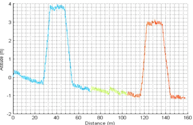
For this test an office worker has worn the system during 5 hours and 30 minutes. The aim is to test the step detector al-gorithm on strides performed naturally, including small steps. During those 5 hours and 30 minutes, the person was mostly sitting on his office chair. These periods are also interesting because the ankle does not remain inactive and it is important that no stride is wrongly detected. The recording contains 3 walking periods including up and down stairs in the first and last one. The overall trajectory is shown in Figure5.
Fig. 5: Trajectory, test B.
As the system was not installed and removed at exactly the same location, the total error can not be calculated by comparing the start and end positions, but there are 3 way-points available pointed out on the Figure5and zoomed on the Figures6,7and8. We can see that the difference of position is less than 50 cm at each waypoint. Moreover, the stairs are
correctly handled as can be seen on the altitude (Figure9) and no stride were wrongly detected while sitting.
Fig. 6: Waypoint 1, test B.
Fig. 7: Waypoint 2, test B.
Fig. 8: Waypoint 3, test B.
Fig. 9: Altitude, test B.
VI. CONCLUSION AND FUTURE WORK
This paper describes an algorithm that allows to detect when a stride occurs with its start and end points from inertial sensors worn on the ankle. This work is divided in four main steps:
• The selection of candidate intervals that may correspond to strides.
• The calculation of a rotation applied on the data in order to work in the same frame for all records. This step is built on fitting the gyroscope data with 3D geometric patterns.
• The extraction of the forward swing on the gyroscope axis y. These data are then fitted with 1D reference patterns. • The binary classification of the intervals using the
Gra-dient Boosting Tree algorithm with features computed along the previous steps.
This algorithm is used in combination with a ZUPT inspired method for trajectory reconstruction. For normal walking it has shown good results achievable with existing algorithms. But the method described in this paper also has a good sensitivity for atypical strides such as small steps, side steps and backward walking contrary to most algorithms proposed in the literature. Moreover those approaches are likely to produce detection error when the system wearer is moving his ankle but not walking (e.g. sitting). This is a problem as non walking motion would be integrated by error in the trajectory. Our algorithm handles those situations without false detection.
Two challenging tests have been performed with all strides successfully identified. However the trajectory reconstruction could be improved by adjusting the estimation of the ankle speed when the foot is on the ground.
REFERENCES
[1] E. Dorveaux, “Magneto-inertial navigation: principles and application to an indoor pedometer,” PhD thesis, École Nationale Supeure des Mines de Paris, 2011.
[2] M. H. C. I. Chesneau and C. Prieur, “Motion estimation of a rigid body with an ekf using magneto-inertial measurements,” Indoor Positioning and Indoor Navigation (IPIN), 2016.
[3] Y. Chen and H. Kobayashi, “Signal strength based indoor geolocation,” Proceedings of the IEEE International Conference on Communications, pp. 436–439, 2002.
[4] V. Renaudin, “Uwb and mems based indoor navigation,” The Journal of Navigation, vol. 61, pp. 369–384, 2008.
[5] S. S. et al., “Hybrid localization using uwb and inertial sensors,” IEEE Int. Conf. Ultra-Wideband (ICUWB), pp. 89–92, 2008.
[6] C. H. K Abdulrahim, T Moore and C. Hill, “Understanding the perfor-mance of zero velocity updates in mems-based pedestrian navigation,” International Journal of Advancements in Technology, vol. 5, no. 2, 2014.
[7] E. Foxlin, “Pedestrian tracking with shoe-mounted inertial sensors,” IEEE Computer graphics and applications, pp. 38–46, 2005. [8] A. M. Sabatini, “Quaternion-based strap-down integration method for
applications of inertial sensing to gait analysis,” Medical and Biological Engineering and Computing, pp. 94–101, 2005.
[9] D. M. S. E. E. K. S. J. Bamberg, A. Y. Benbasat and J. A. Paradiso, “Gait analysis using a shoe-integrated wireless sensor system,” IEEE transactions on information technology in biomedicine, pp. 413–423, 2008.
[10] V. R. M. Susi and G. Lachapelle, “Motion mode recognition and step detection algorithms for mobile phone users,” Sensors, pp. 1539–1562, 2013.
[11] N. O. B. Florentino-Liano and A. Artes-Rodriguez, “Human activity recognition using inertial sensors with invariance to sensor orientation,” Conf. Cognitive Information Processing (CIP), 2012.
[12] M. K. S. Ghose, J Mitra and J. Dowling, “Human activity recognition from smart-phone sensor data using a multi-class ensemble learning in home monitoring,” Stud Health Tehcnol Inform, 2015.
[13] N. Castaneda and S. Lamy-Perbal, “An improved shoe-mounted inertial navigation system,” International conference on indoor positioning and indoor navigation (IPIN), 2010.
[14] T. B. J-L Carrera, Z. Zhao and Z. Li, “A real-time indoor tracking system by fusing inertial sensor, radio signal and floor plan,” International conference on indoor positioning and indoor navigation (IPIN), 2016. [15] Z. K. A. Norrdine and J. Blankenbach, “Step detection for zupt-aided
inertial pedestrian navigation system using foot-mounted permanent magnet,” International conference on indoor positioning and indoor navigation (IPIN), 2016.
[16] P. H. T. Moder, K. Wisiol and M. Wieser, “Smartphone-based indoor positioning utilizing motion recognitiont,” International conference on indoor positioning and indoor navigation (IPIN), 2015.
[17] S. Y. Cho and C.-G. Park, “Mems based pedestrian navigation system,” Journal of Navigation, vol. 59, pp. 135–153, 2006.
[18] H. P. Dikshit and P. Powar, “Discrete cubic spline interpolation,” Numerische Mathematik, vol. 40, pp. 71–78, 1982.
[19] J.-P. Berrut and L. N. Trefethen, “Barycentric lagrange interpolation,” SIAM (Society for Industrial and Applied Mathematics) Review, 2004. [20] J. H. Friedman, “Computational statistics and data analysis,” 2002. [21] M. Stone, “Cross-validatory choice and assessment of statistical
predic-tions,” Journal of the Royal Statistical Society, pp. 111–147, 1974. [22] R. O. L. Breiman, J. Friedman and C. Stone, “Classification and