HAL Id: cea-02176128
https://hal-cea.archives-ouvertes.fr/cea-02176128
Submitted on 7 Jul 2019HAL is a multi-disciplinary open access archive for the deposit and dissemination of sci-entific research documents, whether they are pub-lished or not. The documents may come from teaching and research institutions in France or abroad, or from public or private research centers.
L’archive ouverte pluridisciplinaire HAL, est destinée au dépôt et à la diffusion de documents scientifiques de niveau recherche, publiés ou non, émanant des établissements d’enseignement et de recherche français ou étrangers, des laboratoires publics ou privés.
INSPEX: Make environment perception available as a
portable system
J. Foucault, Suzanne Lesecq, O. Debicki, N. Mareau, J. Barrett, S. Rea, A.
Mcgibney, F. Birot, H. de Chaumont, J Banach, et al.
To cite this version:
J. Foucault, Suzanne Lesecq, O. Debicki, N. Mareau, J. Barrett, et al.. INSPEX: Make environ-ment perception available as a portable system. Smart System Integration (SSI) EPOSS, Apr 2019, Barcelone, Spain. �cea-02176128�
INSPEX: Make environment perception available as a portable
system
J. Foucault, S. Lesecq, O. Debicki, N. Mareau, L. Ouvry, Univ. Grenoble Alpes, CEA, LETI, F-38000 Grenoble, [email protected]
M. Correvon, G. Dudnik, CSEM SA, 2002 Neuchâtel, Switzerland J. Barrett, S. Rea, A. McGibney, Cork Institute of Technology, Ireland F. Birot, H. de Chaumont, GoSense, Lyon, France
R. Banach, J. Razavi, School of Computer Science, Univ. of Manchester, U.K. J. Herveg, F. Thiry, Univ. of Namur, Belgium
C. Jackson, S. Buckley, SensL, Ireland
A. di Matteo, V. Di Palma, M. Passoni, F. Quaglia, STMicroelectronics Srl, Naples, Italy C. Ó’Murchú, R. O’Keeffe, Tyndall National Institute, Cork, Ireland
1 Context
Obstacle avoidance systems for autonomous vehicles combine multiple sensing technologies (i.e. LiDAR, Radar, Ultrasound and Visual) to detect different types of obstacles across the full range of lighting and weather conditions. Sensor data are fused with vehicle orientation (obtained for instance from an Inertial Measurement Unit and/or compass) and navigation subsystems. Power hungry, they require powerful computational capability, which limits their use to high-end vehicles and robots.
2 INSPEX ambition
The H2020 INSPEX project plans to make obstacle detection capabilities available as a personal portable multi-sensors, miniaturised, low power device. This device will detect, locate and warn of obstacles under different environmental conditions, in indoor/outdoor environments, with static and mobile obstacles. Potential applications range from safer human navigation in reduced visibility conditions (e.g. for first responders and fire brigades), small robot/drone obstacle avoidance systems to navigation for the visually and mobility impaired people.
As primary demonstrator (Fig.1), we will plug the INSPEX device on a white cane (see Fig. 1) for Visually Impaired and Blind (VIB) people to detect obstacle over the whole person height, provide audio feedback about harmful obstacles, improve their mobility confidence and reduce injuries, especially at waist and head levels [1]. The device will offer a “safety cocoon” to its user.
Electronic white canes already exist as products [2]. However, co-integration of several range sensor technologies will improve their detection capabilities.
The partners brought to the project early prototypes of short and long range LiDARs (CSEM [5], Tyndall and SensL [4]), Ultra Wide Band RF radar (CEA [3]) and Ultrasound (STMicroelectronics [6]). SigmaFusion®, which a data fusion algorithm based on Bayesian theory, is also part of the inputs [7]. The system firmware will be evaluated using formal methods.
During the first year of the project, the partners collected users’ needs and requirements. Then, they derived the system requirements [8] and finally they proposed the system architecture [9].
3 Overview of the 2nd project year achievements
Figure 1 : INSPEX first version of the integrated prototype (mock-up)
During the second year of the project, we developed a mock-up of the integrated system. We designed and manufactured the General Processing Platform (see Fig. 2). This platform acquires data from the different range sensors and from an Inertial Measurement Unit. It fuses these data to build a model of the environment. Then, it analyses this model, and finally, it sends information about obstacles that enter the safety cocoon to a smartphone through Bluetooth Low Energy.
Formal modelling process applied in the context of INSPEX has been studied [10]. Because formal methods can provide tangible benefits to end-users, facilitating the advance of cutting-edge technology where consumer trust is critical.
The INSPEX partners strived to integrate the range sensors in the INSPEX system. We optimised the size, the weight and the power consumption of each sensor, taking into account user-needs and system requirements as defined during the 1st year of the
project. These results constitute major achievements of the 2nd year of the project.
4 Range sensor optimization prior their integration in the INSPEX system
We chose to develop a stand-alone module for each sensor to extend their potential exploitation. Achievements for the four submodules are now summarised.
4.1 Ultrasound module
The Ultrasound Module is composed of a main board with the driving electronic and a
UWB radar Short Range Lidar Long Range Lidar Ultrasound General Processing Platform
transducer board mounted on top of the main board (see Fig. 3). Its features are: up to 4 transducers;
up to 4 TX/RX ASICs; STM32L4 Microcontroller;
temperature/humidity sensor (to compensate speed of sound); external power supply (12V and 3.3V);
communication on I2C bus.
Fig. 3: Ultrasound boards for the INSPEX system
To measure the distance with respect to a target, we developed an algorithm based on cross-correlation between the received signal and a fixed reference echo. The algorithm runs in real-time on the microcontroller at up to 25 measures per second.
Figure 4: Distance detection of the Ultrasound module
The measurement accuracy was characterized with 2x MA40HIS transducers, a 35x35cm cardboard target, single measurements (no averaging), and tape measure as reference. The distance error, without any compensation, has a mean of 0.49 cm and a standard deviation of 0.68 cm in a range up to 2 meters (see Fig. 4).
4.2 “Long Range” LiDAR module
The “Long Range” LiDAR module has a footprint of 45mm x 51mm, which is a significant reduction from the initial prototype brought to the project which was 119mm x 77mm. Its design is modular with an optics board and a motherboard (see Fig. 5). This provides design flexibility, especially when used in conjunction with the other modules on the INSPEX board.
The power consumption has been drastically reduced through the use of novel design in the motherboard so that even though the laser requires high power (25W) the overall power for the board is ~400mW while the initial prototype required a power of 1.32W.
For improved imaging, lenses are added to the board, which slightly increases the height but not the footprint of the board.
The design can be further improved by the use of molded lenses in a to18 package to focus the optics the next version of this module. The size of the module can be even more reduced by removing the Bluetooth communication and by using a microbead FPGA.
Figure 5: Long range LiDAR module (optic board on top of mother board)
Figure 6: Short Range LiDAR
4.3 Short range LiDAR module
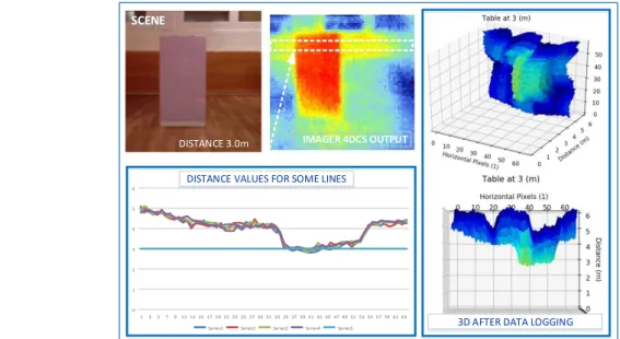
The Short Range Lidar detects obstacles within a volume of 4.0m × 2.0m × 1.5m. The submodule should be able to detect obstacles as small as 0.1m x 0.1m at a user speed of about 5km/h.
The developed submodule is based on a 3D time-of-flight imager with a resolution of 160x60 pixels that can achieve a frame rate of up to 128fps with an absolute accuracy in the centimetre range after calibration and runtime compensation. The design consists in three PCBs split by functions (power supply, controller and leds driver) (see Fig. 6). The optical part is based on a newly designed holder and commercial components, the whole customized and optimized for the INSPEX application.
The Short Range LiDAR module is currently being optimised; it will embed the measurement calibration in its microcontroller.
Figure 7 shows some image captures and the distance measurement capabilities of the module.
4.4 Ultra Wide Band RF Radar module
The Ultra Wide Band radar module is mainly an optimization in form factor and integration of the initial prototype. Its main characteristics are:
8 GHz operation (instead of 4 GHz for the prototype);
Antenna : Azimuth beam 56° (3dB), 118° (10dB), Elevation beam 56° (3dB), 118° (10dB), linear, vertical polarization;
Up to 10m range, 15cm resolution, 200 Hz raw data refresh rate (acquisition rate); Non-ambiguous relative speed estimation over [-1.875, 1.875] m/s;
SPI interface to the General Processing Platform (GEP); Low level Signal processing performed on the GEP.
Note that reducing (main target for this module) the form factor prevented to integrate a larger antenna array that could have provided an estimation of the angle of arrival (i.e. azimuth) of obstacles backscattered signals. Thus, the smallest PCB size was decided which meant the simplest 2-elements single polarization antenna choice. Fig.8 shows the 3 boards that are stacked to obtain the UWB RF radar (Fig. 9). The RF board contains the UWB ASIC and the COTS ADC. The Digital board has the FPGA and the SPI interface to the GEP.
Figure 8: Antenna board (left), RF board(middle), Digital board (right)
The module size is 56*24*30mm3 (without the
connector to the GEP); its weight is 25g; its overall volume is ~44 cm3.
The current consumption is equal to 250mA, which is comparable to the prototype. Standby mechanisms control the consumption when the Radar is inactive by making use of the ADC and the
UWB Asic power-down modes, with fast startup. Figure 9: UWB Radar module
Figure 7: set-up image captures, distance measurement capabilities
DISTANCE 3.0m 0 1 2 3 4 5 6 1 3 5 7911 13 15 17 19 21 23 25 27 29 31 33 35 37 39 41 43 45 47 49 51 53 55 57 59 61 63 table 3.0m
Series1 Series2 Series3 Series4 Series5
SCENE
DISTANCE VALUES FOR SOME LINES
3D AFTER DATA LOGGING
4.5 Progress towards an advanced version of the submodules
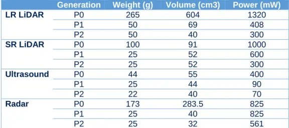
Table 1 summarizes the weight, size (volume) and power consumption of the four modules. P0 corresponds to the prototypes brought to the project by the partners; P1 corresponds to the first version of the optimized modules as achieved during the second year of the project; P2 is the final version of the modules delivered at the end of the project.
Generation Weight (g) Volume (cm3) Power (mW)
LR LiDAR P0 265 604 1320 P1 50 69 408 P2 50 40 300 SR LiDAR P0 100 91 1000 P1 25 52 600 P2 25 52 300 Ultrasound P0 44 55 400 P1 25 44 90 P2 22 40 70 Radar P0 173 283.5 825 P1 25 40 825 P2 25 32 561
Table 1: Evolution of the different submodules (P0: prototype; P1 1st version of the
optimised module; P2: final version of the submodules)
We can see that each module has been optimised to comply with the system requirement with massive reduction in its weight and volume and power consumption. Note that more effort are currently done to decrease even more these figures and obtain truly low-power light weight modules by the end of the project.
5 Development of the integrated system prototype
Fig. 4 shows the integrated smart spatial exploration system that will be delivered in Q3-2019.
End-users will test this prototype in real-life environments. Data from the four optimised modules are fused to build a model of the user surrounding. The obstacles that enter the “safety cocoon” defined around the user will be sent via Bluetooth Low Energy (BLE) to the user’s smartphone, which is in charge of the 3D audio feedback.
We will also analyse the system reliability, especially regarding vibration and EMC.
6 Conclusion
The four range sensor prototypes (Ultrasound, Long Range LiDAR, Short Range LiDAR, UWB radar) brought to the project have been optimised to comply with the INSPEX system requirements.
The INSPEX partners chose to develop a stand-alone version of the modules to extend their potential exploitation domains. Therefore, these optimised modules could be even more optimised if we only target the smart white cane market, which is a niche market. For instance, each module possesses a microcontroller to pre-treat the raw data. It could be removed, the pre-treatment being performed on the General Processing Platform. Also, this latter possesses two microcontroller that could be merged.
The project enters the “integration phase” and the “smart spatial exploration device”, which contains the four optimised modules in their stand-alone version, will be delivered at Q3-2019.
Visually Impaired and Blind volunteers will test the INSPEX integrated system during the 4th quarter of 2019.
7 Acknowledgment
INSPEX has received funding from the EU's Horizon 2020 research and innovation programme under grant agreement No 73095, and from the Swiss Secretariat for Education, Research and Innovation (SERI) under Grant 16.0136 730953.
8 References
[1] R. Manduchi, S. Kurniawan, “Mobility-Related Accidents Experienced by People with Visual Impairment”, Research and Practice in Visual Impairment and Blindness, 2011.
[2] Kun (Linda) Li, “Electronic Travel Aids for Blind Guidance – an Industry Landscape Study”, EECS, UC Berkeley, 2015.
[3] L. Ouvry, et al., “UWB Radar sensor characterization for obstacle detection with application to the smart white cane”, SSI 2018.
[4] R. O’Keeffe, et al., “Characterisation of Long Range LiDAR for Obstacle Detection with application to the Visually Impaired and Blind”, SSI 2018.
[5] G. Dudnik, et al., “Short Range LIDAR characterization for obstacle detection with application to a smart white cane”, SSI 2018.
[6] Francesco Foncellino, Flavio Villa, Andrea di Matteo, “Piezoelectric micro-machined ultrasonic transducer (PMUT) and method for manufacturing the PMUT”, patent US2018/0178251 A1, 2018.
[7] T. Rakotovao, et al., “Multi-Sensor Fusion of Occupancy Grids based on Integer Arithmetic,” ICRA 2016.
[8] S. Lesecq, et al., “Towards a portable smart spatial exploration system for environment perception” SSI’2018.
[9] O. Debicki, N. Mareau, L. Ouvry, J. Foucault, S. Lesecq, G. Dudnik, M. Correvon, “INSPEX: Integrated portable multi-sensor obstacle detection device: Application to navigation for visually impaired people”, Design and Automation Conference, IP Track (Best presentation award) 2018
[10] J. Razavi, R. Banach, O. Debicki, N. Mareau, S. Lesecq, J. Foucault, “Exploring Applications of Formal Methods in the INSPEX Project”. in STAFF-18 Workshops post proceedings. Lecture Notes in Computer Science, 2018.