RESEARCH OUTPUTS / RÉSULTATS DE RECHERCHE
Author(s) - Auteur(s) :
Publication date - Date de publication :
Permanent link - Permalien :
Rights / License - Licence de droit d’auteur :
Bibliothèque Universitaire Moretus Plantin
Institutional Repository - Research Portal
Dépôt Institutionnel - Portail de la Recherche
researchportal.unamur.be
University of Namur
Demonstration of the DB-MAIN methodological engine
Roland, Didier
Publication date:
2002
Link to publication
Citation for pulished version (HARVARD):
Roland, D 2002, Demonstration of the DB-MAIN methodological engine..
General rights
Copyright and moral rights for the publications made accessible in the public portal are retained by the authors and/or other copyright owners and it is a condition of accessing publications that users recognise and abide by the legal requirements associated with these rights. • Users may download and print one copy of any publication from the public portal for the purpose of private study or research. • You may not further distribute the material or use it for any profit-making activity or commercial gain
• You may freely distribute the URL identifying the publication in the public portal ?
Take down policy
If you believe that this document breaches copyright please contact us providing details, and we will remove access to the work immediately and investigate your claim.
DB-Main Manual Series
The University of Namur - LIBD
D
EMONSTRATION
OF
THE
DB-MAIN
M
ETHODOLOGICAL
E
NGINE
WITH
DB-MAIN 6.5 - M
ARCH
2002
1. Introduction
This paper is a “learning by example” demonstration of how to perform the design of a simple database.
This design will be carried out step by step. This method, shown in appendix A, is defined by a method
engineer, using the MDL language [ROLAND,02].
The small case study concerns a library. It contains books that can be borrowed. The database is aimed
at registering all books of the library, all the borrowers and their borrowings. Its complete definition is
given in appendix B, its conceptual schema in appendix C. During the demonstration, we will transform
this schema in a relational schema and generate an SQL DDL script.
2. How to read this paper
•
Bold characters are used to show menu entries to select, or static text in dialogue boxes.
•
Italics is used to show what has to be typed by the user.
•
[...] shows a button to push.
•
“ ... ” shows a graphical object (process type, process, product) that can be found in a window, or a
file name.
•
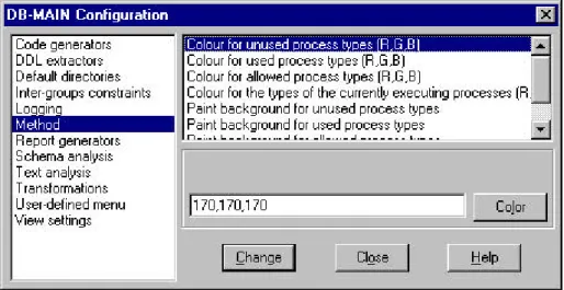
In the drawings, four colour schemes are used to draw rectangles for representing their state. These
schemes can be changed in DB-MAIN through the menu entry File/Configuration... and the
"Method" category, as shown in Figure 2.1. The four schemes are:
•
grey border and white background for unused process types
•
black border and white background for used process types
•
green border and white background in DB-MAIN, changed to ligth gray border and background
in this paper, for allowed process types
•
red border and white background, changed to dark gray border and background in this paper, for
executing process types.
3. Demonstration 3
3. Demonstration
The DB-MAIN CASE tool is started, its workspace is blank. We will create a new project.
Menu File/New project
Name: Library
Short name: lib
Methodology: forward.lum (content in appendix A) (also selectable by pushing [Browse])
[OK]
The project is created, the project window is opened, and, on top of it, another window containing the
method that we will follow (see first figure in appendix A.2). The method is displayed in a graphical
way. Rectangles are process types, i.e. the definition of the processes to perform. Ellipses are product
types, i.e. the definition of the products to generate: all the schemas at every step and the SQL-DDL
script. Bold arrows show the control flow, and the thin arrows show the data flow.
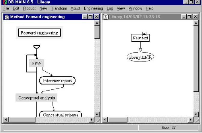
Execute “New” (in the method window, click on the “New” process type (allowed colour) with the
mouse right button; a contextual menu appears, select Execute).
Select the file “library.txt” (content in appendix B).
Change version number to “IR”
[OK]
In the project window (see figure 3.1), we can see that the “New text” process has been created, as well
as the “library.txt” text have been added to the history. An arrow shows that the text is the output of the
process.
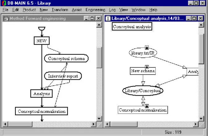
Figure 3.1 - The analyst can choose between two process types
In the method window, the “New” process type is still allowed, and a second one, “Conceptual
analy-sis”, is allowed too. It means that the analyst can choose either to add as many interview reports as he or
she wants to the project or proceed with the conceptual analysis of these reports. It is to be noticed that,
during the execution of the “New text” process, the “New” process type was in the executing colour to
show that a process of that type is in progress.
In our example, we will do with our single text and go on with its analysis.
Execute “Conceptual analysis”.
[OK]
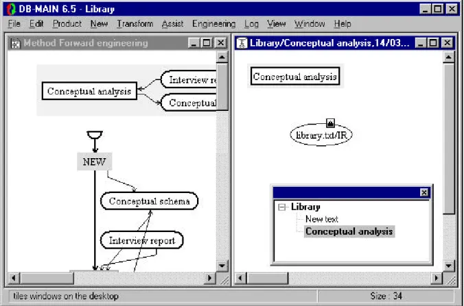
The content of the method window is changed. It shows the strategy of the “Conceptual analysis”
pro-cess type (figure 3.2). The project window has changed in the same way: a “Conceptual analysis”
engi-neering process has been created, and the window shows it. By opening the process hierarchy window
(menu Window/Process hierarchy), we can see that “Conceptual analysis” is a sub-process of Library.
We can use the hierarchy window to browse through the history
.
Figure 3.2 - Beginning the conceptual analysis
We can now perform the conceptual analysis by first creating a new schema that will be used as the
drawing board.
Execute “New”.
Name: Library
Short name: lib
Version: Conceptual
[OK]
On this drawing board, we will now introduce the conceptual schema of our library management
sys-tem during the analysis process.
Execute “Analysis”.
[OK]
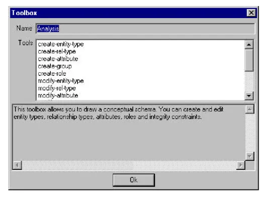
“Analysis” is a primitive process that must be performed by the analyst using a toolbox. By double
clic-king on the “Analysis” process type in the method window, we can see which tools are available in this
toolbox (figure 3.3). They allow the analyst to create and edit entity types, relationship types, attributes,
roles and groups in the schema. So, now, the analyst will have to open the blank schema and fill it by
creating the conceptual schema of the database by its own. When he or she finishes the job, he or she
will signal it to the methodological engine
3. Demonstration 5
.
Figure 3.3 - The analysis toolbox
Open the “Library/conceptual” schema.
Enter the conceptual schema shown in appendix 3.
Close the schema.
In the project window, select the “Analysis” process.
Menu Engineering/End use of primitives.
Terminate “Analysis” (in the method window, click on the “Analysis” process type (in executing
colour) with the mouse right button; a contextual menu appears, select Terminate).
The first conceptual schema being introduced, it can be normalised. To know what it means, just double
click on the “Conceptual normalisation” process type in the method window and read its description.
Execute “Conceptual normalisation”.
[OK]
Open the “Library/Conceptual” schema.
We can see that this simple schema is already normalised, so we can immediately close the window.
Select “Conceptual normalisation” in the project window.
Menu Engineering/End use of primitives.
Terminate “Conceptual normalisation”
The conceptual analysis is finished (see figure 3.4). The CASE tool automatically terminates it: the
CASE tool automatically performs the same action as the user could perform by selecting the menu
entry Engineering/End current process with nothing selected in the project window. A dialogue box
appears to allow the user to select output products, as shown in figure 3.5. Since the process type
speci-fies there should be conceptual schema(s) in output, and since we have only one schema in our project,
this schema is proposed in output. We accept this choice and we terminate the use of conceptual
analy-sis process type::
[OK]
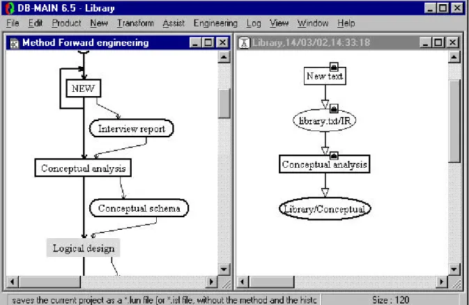
Terminate “Conceptual analysis”.
Both the project and the method windows are back to their first view, the one before we began the
“Conceptual analysis” process. In the method window, only the “Logical design” process type is now in
the state allowed (figure 3.6).
Figure 3.4 - The conceptual analysis is finished
Figure 3.5 - The output product selection dialogue box.
Execute “Logical design”.
[OK]
Execute “Copy”.
Version: First logical
[OK]
Execute “Relational design”.
[OK]
3. Demonstration 7
Figure 3.6 - Ready for logical design
The following process types are primitive process types. The “New” and “Copy” process types we
already met are also primitive process types, but built-in process types: the CASE tool knows by itself
what to do. The “Analysis” process type met during the conceptual analysis was an analyst-driven
pri-mitive process type. The following ones are of a third kind: they are method-driven pripri-mitive process
types. By double-clicking on them in the method window, one can see a script of transformations that
were specified by the method engineer and that will be executed automatically by the CASE tool.
Execute “Is-a relations”.
[OK]
Execute “Non-functional rel-types”.
[OK]
Execute “Attributes”.
[OK]
Execute “Identifiers”.
[OK]
Execute “References”
[OK]
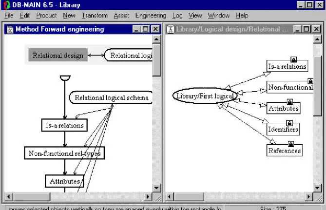
Relational design is over (figure 3.7) and the Engineering/End current process function is executed.
[OK]
Terminate “Relational design”.
We can go on with the logical design by keeping a copy of the current state of the schema and
transfor-ming all the names in order for them to be compliant with the SQL standard.
Figure 3.7 - End of relational design
Execute “Copy”.
Version: Logical
[OK]
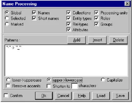
Execute “Name conversion”.
[OK]
Open “Library/logical”.
Menu Transform/Name processing. (see figure 3.8)
"-" -> "_"
[lower -> uppercase]
[OK]
Close the schema
Select “Name conversion” in the project window
Menu Engineering/End use of primitives.
Terminate “Name conversion”.
The logical design is over (figure 3.9) and the CASE tool automatically terminates it: the schema
“Library/Logical” is proposed in output, and the schema “Library/First logical” is put in the
“candidates” list, that is to say it is not proposed in output, but the user can decide to use it in output
anyway. We simply accept the proposed solution.
[OK]
Terminate “Logical design”.
The same way, we can perform the physical design of our database.
Execute “Physical design”.
[OK]
Execute “Copy”.
Version: Physical
[OK]
3. Demonstration 9
Figure 3.8 - Name processing
Figure 3.9 - End of logical design
A method engineer-driven primitive process will create indexes automatically where they are probably
the most useful.
Execute “Setting indexes”.
[OK]
A user-driven primitive process allows the database engineer to manually specify the database files to
create and to distribute the tables among those files.
Execute “Storage allocation”.
[OK]
Open schema “Library/Physical”.
Create two collections and fill them:
- LIBRARY (AUTHOR,BOOK,COPY,KEYWORD,REFERENCE,WRITTEN)
- BORROWING(BORROWER,BORROWING,CLOSED_BORROWING,PHONE,PROJECT)
Close the schema.
Select “Storage allocation” in the project window.
Menu Engineering/End use of primitives.
Terminate “Storage allocation”.
The physical design is over (see figure 3.10) and terminated automatically by the CASE tool with
“Library/Physical” as proposed output product.
Figure 3.10 - End of physical design
[OK]
Terminate “Physical design”.
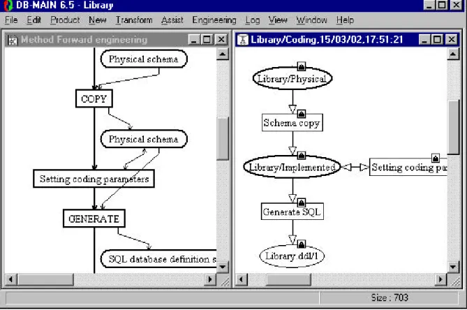
And finally the coding step will generate the SQL-DDL script.
Execute “Coding”.
[OK]
Execute “Copy”.
Version: Implemented
[OK]
Execute “Setting coding parameters”.
[OK]
3. Demonstration 11
The technical descriptions can be modified by introducing some coding parameters. They will be
inter-preted by the SQL generator. For instance, the technical description could specify, for each access key,
if it must be implemented with a b-tree, or with hashing.
We will not bother with these optimisations in this small case study.
Close the schema.
Select “Setting coding parameters” in the project window.
Menu Engineering/End use of primitives.
Terminate “Setting coding parameters”.
Finally, the SQL generator can be invoked.
Execute “Generate”.
File Name: LIBRARY.DDL
[Save]
The CASE tool automatically terminates the “Coding” process with “library.dll/1” as the proposed
out-put product.
[OK]
Terminate “Coding”.
Both the coding (figure 3.11) and the project (figure 3.12) are terminated.
Figure 3.12 - End of the project
4. Bibliography
[ROLAND,02] D. Roland, MDL Programmer’s Guide, technical report, FUNDP, Institut
d’informatique, http://www.db-main.be 2002.
Appendix A. The method 13
Appendix A. The method
A.1 The MDL listing
% Product models definitions %%%%%%%%%%%%%%%%%%%%%%%%%%%% text-model TEXT_FILE
title "Text file" description
A text file contains some free text. In this method, we will use them to store reports written in natural language.
end-description extensions "TXT" end-model text-model SQL_FILE title "SQL file" description
An SQL script containing SQL instructions for the creation of a database including create database, create table, create index, alter table with checks, create trigger,...
end-description
extensions "SQL", "DDL" end-model
schema-model PHYS_SQL_SCHEMA title "SQL schema model" description
The SQL schema model maps the generic entity/object-relationship (GER) model of DB-MAIN to an SQL relational model, including physical characteristics such as the setting of indexes and the definition of dataspaces.
This is the schema model from which database creation scripts can be derived. This is the schema can be used as a reference for the database administrator to fine tune the database.
end-description concepts
collection "table space" schema "view"
entity_type "table" atomic_attribute "column" user_constraint "constraint"
identifier "unique constraint" primary_identifier "primary key" access_key "index" constraints
ET_per_SCHEMA (1 N) % At list one table required diagnosis "Schema &NAME should have a table" RT_per_SCHEMA (0 0) % No rel-type allowed diagnosis "Rel-type &NAME should not exist"
ATT_per_ET (1 N) % At least one column per table diagnosis "Table &NAME should have at least one column" PID_per_ET (0 1) % At most one primary key per table diagnosis "Table &NAME has too much primary keys"
SUB_TYPES_per_ISA (0 0) % Is-a relations are not allowed
diagnosis "Is-a relations are not allowed and &NAME has a sub-type" ID_NOT_KEY_per_ET (0 0) % Every unique constraint is an index
diagnosis "Unique constraint &NAME should be an index"
OPT_ATT_per_EPID (0 0) % Optional columns not allowed in primary keys. diagnosis "There should be no optional column in primary key &NAME." DEPTH_of_ATT (1 1) and MAX_CARD_of_ATT (1 1)
diagnosis "Column &NAME should be atomic and single-valued."
ALL_CHARS_in_LIST_NAMES (ABCDEFGHIJKLMNOPQRSTUVWXYZabcdefghijklmnopqrstuvwxyz 0123456789$_) and NONE_in_LIST_NAMES (_$,$$)
and LENGTH_of_NAMES (0 31)
diagnosis "The name &NAME is invalid" end-model
schema-model LOG_SQL_SCHEMA
title "Logical relational schema" description
The logical relational schema model maps the generic entity/object-relationship (GER) model of DB-MAIN to a generic relational model, without any specific RDBMS in mind. Schemas compliant with this model are the one to give as a reference to people who need to write queries on the database.
end-description concepts schema "view" entity_type "table" atomic_attribute "column" user_constraint "constraint"
identifier "unique constraint" primary_identifier "primary key" constraints
ET_per_SCHEMA (1 N) % At list one table required diagnosis "Schema &NAME should have a table" RT_per_SCHEMA (0 0) % No rel-type allowed diagnosis "Rel-type &NAME should not exist"
COLL_per_SCHEMA (0 0) % No collection/table space allowed diagnosis "The schema should have no table space"
ATT_per_ET (1 N) % At least one column per table diagnosis "Table &NAME should have at least one column" PID_per_ET (0 1) % At most one primary key per ET diagnosis "Table &NAME has too many primary keys" KEY_per_ET (0 0) % No access keys/indexes diagnosis "Table &NAME should not have an index" SUB_TYPES_per_ISA (0 0) % Is-a relations are not allowed
diagnosis "Is-a relations are not allowed and &NAME has a sub-type" OPT_ATT_per_EPID (0 0) % Optional columns not allowed in primary keys. diagnosis "There should be no optional column in primary key &NAME." DEPTH_of_ATT (1 1) and MAX_CARD_of_ATT (1 1)
% Columns are atomic and single-valued
diagnosis "Column &NAME should be atomic and single-valued." end-model
schema-model CONCEPT_SCHEMA title "Conceptual schema model" description
The conceptual schema model allows an analyst to draw a representation of the real world. A schema compliant with that model shows precisely, in a readable way, the semantics of the database. It cannot be directly implemented. Its main purpose is to be a basis for documenting the database, to be a support for dialogue.
end-description concepts
schema "schema" entity_type "entity type" rel_type "relationship type" atomic_attribute "attribute"
compound_attribute "compound attribute" role "role"
group "group" user_constraint "constraint" constraints
Appendix A. The method 15
ET_per_SCHEMA (1 N) % At list one ET required diagnosis "Schema &NAME should have an entity type" COLL_per_SCHEMA (0 0) % No collection allowed diagnosis "The schema should have no collection"
ATT_per_ET (1 N) % At least one attribute per ET
diagnosis "Entity type &NAME should have at least one attribute" KEY_per_ET (0 0) % No access keys
diagnosis "Entity type &NAME should not have an access key" REF_per_ET (0 0) % No foreign key
diagnosis "Entity type &NAME should not have a foreign key"
ID_per_ET (1 N) % If there are identifiers, one of them is primary and PID_per_ET (1 1)
or ID_per_ET (0 0)
diagnosis "One of the identifiers of entity type &NAME should be primary" EMBEDDED_ID_per_ET (0 0) % Embedded identifiers are not allowed"
diagnosis "Embedded identifiers should be removed in entity type &NAME" ID_DIFF_in_ET (components) % All identifiers must have different components diagnosis "Identifiers made of the same components should be avoided in &NAME" TOTAL_in_ISA (no) % Total is-a relations should concern at least or TOTAL_in_ISA (yes) % two subtypes
and SUB_TYPES_per_ISA (2 N)
diagnosis "Total is-a relations are not allowed with only one sub-type" DISJOINT_in_ISA (no) % Disjoint is-a relations should concern at least or TOTAL_in_ISA (yes) % two subtypes
and SUB_TYPES_per_ISA (2 N)
diagnosis "Disjoint is-a relations are not allowed with only one sub-type" ROLE_per_RT (2 2) % 2 <= degree of a rel-type <= 4
or ROLE_per_RT (3 4) % if 3 or 4, the rel-type cannot have a one role and ATT_per_RT (1 N) % or it must also have attributes
or ROLE_per_RT (3 4) and ATT_per_RT (0 0) and ONE_ROLE_per_RT (0 0)
diagnosis "Rel-type &NAME has too many roles, or too few attributes"
ID_per_RT (1 N) % If RT have some identifiers, one of them is primary and PID_per_RT (1 1)
or ID_per_RT (0 0)
diagnosis "One of the identifiers of rel-type &NAME should be primary" EMBEDDED_ID_per_RT (0 0) % Embedded identifiers are not allowed" diagnosis "Embedded identifiers should be removed in rel-type &NAME" ID_DIFF_in_RT (components) % All identifiers must have different components diagnosis "Identifiers made of the same components should be avoided in &NAME" not SUB_ATT_per_ATT (1 1) % Compound attribute must have at least two components diagnosis "Compound attribute &NAME has too few sub-attributes"
ID_per_ATT (0 0) % A compound attribute cannot have an identifier diagnosis "Multi-valued compound attribute &NAME should not have an identifier" COMP_per_GROUP (1 N) % Every group must have at least one component
diagnosis "Group &NAME should have components"
ROLE_per_EID (0 0) % An ET identifier cannot be made of a single role and COMP_per_EID (1 N)
or ROLE_per_EID (1 N) and COMP_per_EID (2 N)
diagnosis "ET Identifier &NAME should have another component"
MULT_ATT_per_EID (1 1) % If an ET identifier contains a multi-valued attribute and COMP_per_EID (1 1) % it must be the only component.
or MULT_ATT_per_EID (0 0)
diagnosis "ET id. &NAME should have no multi-valued att. or no other component" ONE_ROLE_per_EID (0 0) % An entity type identifier should not have a one-role diagnosis "One-roles should be removed from entity type identifier &NAME" OPT_ATT_per_EPID (0 0) % Optional columns not allowed in primary ids. diagnosis "There should be no optional column in primary id &NAME."
COMP_per_RID (1 1) % If a rel-type identifier has only one component, and ROLE_per_RID (0 0) % it must be an attribute
or COMP_per_RID (2 N)
MULT_ATT_per_RID (1 1) % If a RT identifier contains a multi-valued attribute and COMP_per_RID (1 1) % it must be the only component.
or MULT_ATT_per_RID (0 0)
diagnosis "RT id. &NAME should have no multi-valued att. or no other component" ONE_ROLE_per_RID (0 0) % A rel-type identifier should not have a one-role diagnosis "One-roles should be removed from rel-type identifier &NAME" OPT_ATT_per_RPID (0 0) % No optional attribute in a rel-type identifier diagnosis "Optional attributes should be removed from rel-type id. &NAME" end-model % Toolbox definitions %%%%%%%%%%%%%%%%%%%%% toolbox TB_ANALYSIS title "Analysis" description
This toolbox allows you to draw a conceptual schema. You can create and edit entity types, relationship types, attributes, roles and integrity constraints. end-description add create-entity-type add create-rel-type add create-attribute add create-group add create-role add modify-entity-type add modify-rel-type add modify-attribute add modify-group add modify-role add delete-entity-type add delete-rel-type add delete-attribute add delete-group add delete-role end-toolbox toolbox TB_CONCEPTUAL_NORMALISATION title "Conceptual normalisation" description
This toolbox allows you to enhance the readability of your conceptual schema without modifying its semantics. You can do it by applying some transformations on entity types, relationship types and attributes.
You should be aware of some entity types that look like relationship types (the roles they play are all 1-1 and they are identified by all the roles they play), of some entity types that look like attributes (small, just a few attributes, and they play a single role in a single relationship type), of some entity types that are linked by a one to one relationship type and that have the same semantics, and of large entity types that do not have a clear semantics. end-description add tf-ET-into-att add tf-att-into-ET add tf-RT-into-ET add tf-ET-into-RT add tf-split-merge add modify-entity-type add modify-rel-type add modify-attribute add modify-group add modify-role end-toolbox toolbox TB_NAME_CONVERSION title "Name conversion"
Appendix A. The method 17
description
The names of all objects of the schema should be transformed by removing white spaces, accents and other special symbols.
end-description add name-processing end-toolbox
toolbox TB_SETTING_PARAMETERS title "Setting coding parameters" description
Allows you to update technical descriptions in order to specify a few database engine dependent parameters.
end-description add modify-tech-desc end-toolbox
toolbox TB_STORAGE_ALLOCATION title "Storage allocation" description
Allows you to define what files to create and which table goes in which file. end-description
add create-collection add modify-collection add delete-collection end-toolbox
% Process types definitions %%%%%%%%%%%%%%%%%%%%%%%%%%% process CONCEPTUAL_ANALYSIS title "Conceptual analysis" description
On the basis of interview reports with the future users of the system that will be build, a conceptual schema of the database is drawn. It has to reflect the real world system.
end-description
input Interview_report[1-N] "Interview report" : TEXT_FILE output Conceptual_schema "Conceptual schema" : CONCEPT_SCHEMA strategy
new(Conceptual_schema);
toolbox TB_ANALYSIS [log off] (Conceptual_schema,Interview_report); toolbox TB_CONCEPTUAL_NORMALISATION [log replay] (Conceptual_schema); end-process
process RELATIONAL_TRANSLATION title "Relational design" description
Transformation of a binary schema into a relational (SQL-compliant) schema. end-description
update Logical_schema "Relational logical schema" : LOG_SQL_SCHEMA strategy
% Transform is-a relations
glbtrsf "Is-a relations" (Logical_schema,ISA_into_RT); % Transform all non-functional rel-types
glbtrsf "Non-functional rel-types" (Logical_schema,
RT_into_ET(ROLE_per_RT(3 N) or ATT_per_RT(1 N)), SPLIT_MULTIET_ROLE,
RT_into_ET(N_ROLE_per_RT(2 2))); % Transform all compound and/or multi-valued attributes
glbtrsf "Attributes"(Logical_schema, LOOP,
ATT_into_ET_INST(MAX_CARD_of_ATT(2 N)), DISAGGREGATE,
% Add technical identifiers where needed in order to be able to transform all % rel-types into referential constraints
glbtrsf "Identifiers" (Logical_schema,SMART_ADD_TECH_ID); % Transform all rel-types into referential constraints glbtrsf "References" (Logical_schema, LOOP, RT_into_REF, ENDLOOP) end-process process LOGICAL_DESIGN title "Logical design" description
Logical design is the process of transforming a conceptual schema into
a data model compliant schema, a relational model compliant schema in this case. In a first time, the conceptual schema will be simplified (transformed into a binary schema). It will be possible, in a second time, to optimise this simplified schema. In a third time, this optimised schema will be transformed into a relational schema. Finally, a few relational model specific optimisations can be performed.
end-description
input Conceptual_schema "Conceptual schema" : CONCEPT_SCHEMA output Logical_schema "Logical schema" : LOG_SQL_SCHEMA
intern Raw_logical_schema "Raw logical schema" : weak LOG_SQL_SCHEMA strategy
copy(Conceptual_schema,Raw_logical_schema); do RELATIONAL_TRANSLATION(Raw_logical_schema); copy(Raw_logical_schema,Logical_schema);
toolbox TB_NAME_CONVERSION [log all] (Logical_schema); end-process
process PHYSICAL_DESIGN title "Physical design" description
Physical design is the process of updating a logical schema into a DBMS specific schema by adjunction of a series of specific structures like files, access keys,...
end-description
input Logical_schema "Logical schema" : LOG_SQL_SCHEMA output Physical_schema "Physical schema" : PHYS_SQL_SCHEMA strategy
copy(Logical_schema,Physical_schema); % setting indexes
glbtrsf "Setting indexes" (Physical_schema, RENAME_GROUP, GROUP_into_KEY(ID_in_GROUP(YES) or REF_in_GROUP(YES)), REMOVE_PREFIX_KEY); toolbox TB_STORAGE_ALLOCATION(Physical_schema); end-process process CODING title "Coding" description
Coding consites in setting a few database dependent parameters and generating an SQL DDL file.
end-description
input Physical_schema "Physical schema" : PHYS_SQL_SCHEMA
intern Completed_physical_schema "Physical schema" : PHYS_SQL_SCHEMA output SQL_script "SQL database definition script" : SQL_FILE
strategy
copy(Physical_schema,Completed_physical_schema);
toolbox TB_SETTING_PARAMETERS [log replay] (Completed_physical_schema); generate STD_SQL(Completed_physical_schema,SQL_script)
Appendix A. The method 19
process FORWARD_ENGINEERING title "Forward engineering" description
Forward engineering is the process of building a database from a conceptual schema.
In this context, you will have to design an SQL database. end-description
intern Interview_report "Interview report" : TEXT_FILE,
Conceptual_schema "Conceptual schema" : CONCEPT_SCHEMA, Logical_schema "Logical schema" : LOG_SQL_SCHEMA, Physical_schema "Physical schema" : PHYS_SQL_SCHEMA, SQL_script "SQL database definition script" : SQL_FILE strategy repeat new(Interview_report); end-repeat; do CONCEPTUAL_ANALYSIS(Interview_report,Conceptual_schema); do LOGICAL_DESIGN(Conceptual_schema,Logical_schema); do PHYSICAL_DESIGN(Logical_schema,Physical_schema); do CODING(Physical_schema,SQL_script) end-process % Method definition %%%%%%%%%%%%%%%%%%% method
title "Forward engineering" version "1.0"
author "Didier ROLAND" date "28-10-1998"
perform FORWARD_ENGINEERING end-method
A.2 The graphical representation
The main process type
This is the backbone of the method to follow. It is a sequence that allows an analyst to collect a series of
interview reports and to design the whole database on their basis. The four main process types
(concep-tual analysis, logical design, physical design and coding) can be decomposed, as can be seen in the
fol-lowing pages.
The main phases of the method
The following process types are the decomposition of the main process types from the previous page.
The logical design contains itself an engineering process type (relational design) that is shown here too.
Forward engineering Interview report NEW Interview report Conceptual schema Conceptual analysis Conceptual schema Logical schema Logical design Logical schema Physical schema Physical design Physical schema
SQL database definition script Coding
Appendix A. The method 21 Conceptual analysis Interview report Conceptual schema Conceptual schema NEW Conceptual schema Interview report Analysis Conceptual schema Conceptual normalisation Logical design Conceptual schema Logical schema Conceptual schema
Raw logical schema COPY
Raw logical schema
Relational design
Raw logical schema
Logical schema COPY
Logical schema
Relational design Relational logical schema
Relational logical schema
Is-a relations
Relational logical schema
Non-functional rel-types
Relational logical schema
Attributes
Relational logical schema
Identifiers
Relational logical schema
References Physical design Logical schema Physical schema Logical schema Physical schema COPY Physical schema Setting indexes Physical schema Storage allocation
Appendix A. The method 23
Coding
Physical schema
SQL database definition script
Physical schema
Physical schema COPY
Physical schema
Setting coding parameters Physical schema
SQL database definition script GENERATE
Appendix B. The “library.txt” text
Report of the interviews
A book is considered as a piece of literary, scientific or technical writing. Every book has an identifying
number, a title, a publisher, a first published date, keywords, and an abstract (the abstracts are being
encoded), the names of its authors, and its bibliographic references (i.e. the books it references).
For each book, the library has acquired a certain number (0, 1 or more) of copies. The copies of a given
book have distinct serial numbers. For each copy, the date it was acquired is known, as well as its
loca-tion in the library (i.e. the store, the shelf and the row in which it is normally stored), its borrower (if
any), and the number of volumes it comprises. It appears that one cannot borrow any individual
volume, but that one must borrow all the volumes of a copy. In addition, the copies of a given book may
have different numbers of volumes. A book is also characterised by its physical state (new, used, worn,
torn, damaged, etc), specified by a one-character code, and by an optional comment on this state.
The author of a book has a name, a first name, a birth date, and an origin (i.e. the organisation which
(s)he came from when the book was written). For some authors, only the name is known. The
employees admit that two authors may have the same name (and first name), but such a situation does
not seem to raise any problem. Only the authors of books known by the library are recorded.
A copy can be borrowed, at a given date, by a borrower. Borrowers are identified by a personal id. The
library records the name, the first name, the address (name of the company, street, zip-code and city
name), as well as the phone numbers of each borrower. In addition, when (s)he is absent, another
bor-rower (who is responsible for the former) can be contacted instead. When a copy is brought back, it is
put in a basket from which it is extracted at the end of the day to be stored in its location, so that it is
available again from the following day on. A copy is borrowed on behalf of a project (identified by its
name, but also by its internal code). When a copy is brought back to the desk, the employee records the
following information on this copy: borrowing date, current date, borrower and project.
Appendix C. The conceptual schema 25
Appendix C. The conceptual schema
0-N written 1-N 0-N responsible 0-1 responsible-for 0-N reference 0-N origin reference 1-1 0-N of 0-N 0-N 0-N closed-borrowing Borrow-Date End-Date id: COPY Borrow-Date 0-N 0-N 0-1 borrowing Borrow-Date PROJECT Pcode Title id: Pcode id': Title COPY Copy-No Date-Acquired Location Store Shelf Row Nbr-of-Volumes State Comment[0-1] id: of.BOOK Copy-No BORROWER Pid Name First-Name Address Company Street Zip-code City Phone[1-5] id: Pid BOOK Book-id Title Publisher Date-Published Keyword[0-10] Abstract[0-1] id: Book-id AUTHOR Name First-Name[0-1] Origin[0-1] Library/Conceptual
![Figure 3.10 - End of physical design [OK]](https://thumb-eu.123doks.com/thumbv2/123doknet/14541594.724908/11.892.92.766.433.881/figure-end-physical-design-ok.webp)