HAL Id: hal-01140488
https://hal.archives-ouvertes.fr/hal-01140488
Submitted on 9 Apr 2015
HAL is a multi-disciplinary open access
archive for the deposit and dissemination of
sci-entific research documents, whether they are
pub-lished or not. The documents may come from
teaching and research institutions in France or
abroad, or from public or private research centers.
L’archive ouverte pluridisciplinaire HAL, est
destinée au dépôt et à la diffusion de documents
scientifiques de niveau recherche, publiés ou non,
émanant des établissements d’enseignement et de
recherche français ou étrangers, des laboratoires
publics ou privés.
A Meige, Nicolas Plihon, G J M Hagelaar, Jean-Pierre Boeuf, Pascal Chabert,
Rod Boswell
To cite this version:
A Meige, Nicolas Plihon, G J M Hagelaar, Jean-Pierre Boeuf, Pascal Chabert, et al.. Propagating
double layers in electronegative plasmas. Physics of Plasmas, American Institute of Physics, 2007, 14,
pp.053508. �10.1063/1.2736946�. �hal-01140488�
Propagating double layers in electronegative plasmas
A. Meigea兲
Laboratoire Plasma et Conversion d’Energie (LAPLACE), Université Paul Sabatier,
118 route de Narbonne, Toulouse Cedex 31062, France and Space Plasma Power and Propulsion Group, Research School of Physical Sciences and Engineering, Australian National University, ACT 0200, Australia
N. Plihonb兲
Laboratoire de Physique et Technologie des Plasmas (LPTP), Ecole Polytechnique, Palaiseau Cedex 91128, France
G. J. M. Hagelaar and J.-P. Boeuf
Laboratoire Plasma et Conversion d’Energie (LAPLACE), Université Paul Sabatier, 118 route de Narbonne, Toulouse Cedex 31062, France
P. Chabert
Laboratoire de Physique et Technologie des Plasmas (LPTP), Ecole Polytechnique, Palaiseau Cedex 91128, France
R. W. Boswell
Space Plasma Power and Propulsion Group, Research School of Physical Sciences and Engineering, Australian National University, ACT 0200, Australia
共Received 9 February 2007; accepted 30 March 2007; published online 29 May 2007兲
Double layers have been observed to propagate from the source region to the diffusion chamber of a helicon-type reactor filled up with a low-pressure mixture of Ar/ SF6 关N. Plihon et al., J. Appl. Phys. 98, 023306共2005兲兴. In the present paper the most significant and new experimental results are reported. A fully self-consistent hybrid model in which the electron energy distribution function, the electron temperature, and the various source terms are calculated is developed to investigate these propagating double layers. The spontaneous formation of propagating double layers is only observed in the simulation for system in which the localized inductive heating is combined with small diameter chambers. The conditions of formation and the properties of the propagating double layers observed in the simulation are in good agreement with that of the experiment. By correlating the results of the experiment and the simulation, a formation mechanism compatible with ion two-stream instability is proposed. © 2007 American Institute of Physics.
关DOI:10.1063/1.2736946兴
I. INTRODUCTION
An electric double layer共DL兲 is a narrow localized
re-gion within a plasma, not directly attached to a wall, which can sustain a large potential difference共see Ref.1, and ref-erences therein兲. Following general terminology, in this pa-per, the high-potential region is referred to as the “upstream” region and the low-potential region across the DL as the “downstream” region. Double layers have been found in a variety of laboratory plasmas such as in constricted plasmas,2 Mercury discharges,3 Q-machines,4 triple plasma devices,5 expanding plasmas,6 etc. Their role in astrophysics is also considerable as they are thought to be present in the mag-netosphere and responsible for the acceleration of electrons onto the upper atmosphere, creating the fantastic aurora.7–9 Various theories on the formation of solar flares also involve double layers.10It was also proposed that double layers may play a significant role in supplying and accelerating plasma
in magnetic coronal funnels.1,11In most situations in experi-ment, theory, and simulation, the DL is imposed and an elec-tric current flows through it. Since the共independent and
al-most simultaneous兲 work of Charles and Boswell6
and
Cohen et al.12 there has been considerable interest in the
spontaneous formation of double layers in low-pressure
plasmas. Such spontaneous electropositive magnetized
double layers have been studied experimentally,6,13–16
theoretically,17 and by computer simulation.18–21 More re-cently, spontaneous static22 and propagating23 double layers in unmagnetized electronegative plasmas have been reported. Propagating double layers in electronegative plasmas are not only an interesting phenomenon in itself, but also, they need to be understood because of the use of electronegative plas-mas in microelectronics.
It is now well established that double layers can form in
low-pressure electronegative plasmas;24–29 however, the
physical processes underlying the formation of propagating double layers remain unclear. The primary goal of the present paper is to investigate plasma discharges similar to that of Plihon et al.23 so as to shed light on the critical pa-rameters and the conditions of formation of propagating
a兲Now at the Laboratoire de Physique et Technologie des Plasmas共LPTP兲,
Ecole Polytechnique, Palaiseau Cedex 91128, France; Electronic mail: [email protected].
b兲Now at the Laboratoire de Physique UMR CNRS 5672, ENS Lyon, 46 Alle
d’Italie, 69007 Lyon, France.
electronegative double layers by the use of a computer model. The paper is organized as follows: The most signifi-cant and some new experimental results are presented in Sec. II. Section III describes the model. Section IV shows a typi-cal case of spontaneous formation of propagating double lay-ers with the fully self-consistent simulation. Section V pre-sents a parametric study of the propagating double-layer formation. A mechanism for the formation of propagating double layers in electronegative gases is proposed in Sec. VI. The paper is then closed by a few concluding remarks in Sec. VII.
II. EXPERIMENTAL RESULTS
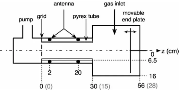
Recent experiments by Plihon et al.16,22,23 have demon-strated that double layers can form in the expanding region of an inductively coupled electronegative plasma in Ar/ SF6
and Ar/ O2 mixtures. The system is composed of a source
chamber, a 30 cm long, 15 cm diameter pyrex tube and sur-rounded by a double-saddle helicon antenna;30the source is attached to a 26 cm long, 32 cm diameter aluminum
diffu-sion chamber. A schematic of the setup is shown in Fig. 1.
The helicon antenna is powered by an rf power supply oper-ating at 13.56 MHz and capable of delivering 2 kW of for-ward power in capacitive or inductive modes.
Plasma parameter measurements reported here were made along the revolution axis共z axis兲 of the discharge using electrostatic probes and probe-based laser induced photode-tachment. Plasma potential, electron density, and electron
temperature were deduced from the I共V兲 characteristics of a
passively compensated Langmuir probe31,32with a 0.25 mm
diameter, 6 mm long platinum wire tip and from usual I-V
curve processing.33A time-resolved setup was developed in
order to capture pseudoperiodic regimes, such as propagating double layers.23
Measurements of the negative ion density are achieved using probe-based laser induced photodetachment, by mea-suring the electron current increase following the detachment of electrons induced by collisions between photons and negative ions.34The electronegativity␣, used throughout the text, is defined as the ratio of the negative ion density n−over the electron density ne. Time-resolved photodetachment
sig-nals were obtained by triggering the frequency tripled Nd:YAG laser pulse on a delayed double-layer birth signal 共the laser pulse period remaining in the range 10 Hz± 0.1 Hz兲. Probing one period of the phenomenon is made possible by the modification of the delay. Averaging over 200 laser pulses leads to a typical laser induced photo-detachment signal.
Plihon et al.16,22 showed that a static double layer is formed in the vicinity of the expanding region of the system 共z⬃30 cm兲 for moderate electronegativities, i.e., for a rather
narrow range of SF6concentrations 共between 8% and 13%兲
and for O2 concentrations above 72% and for a neutral gas
pressure of 1 mTorr. For low electronegativities, no double layer is observed.
At high electronegativities, i.e., in Ar/ SF6mixtures with
SF6 concentrations above 13%, propagating double layers
are observed. A full parametric investigation of the periodic formation of propagating double layers is presented in Ref.
23. As shown in the plasma potential measurements in Fig.
2共a兲, the propagating double layers were born in the vicinity
of the interface between the two chambers 共z⬃26 cm兲 and
propagate downwards, in the diffusion chamber. Note that this regime is periodic-like, with a 5% variation on the pe-riod width. The speed and frequency of these propagating DLs are such that irrespective of the parameters, the number of DLs simultaneously present in the system is constant. The
speed of propagation is of the order of 150 m / s 共which is
much slower than the ion sound speed under present condi-tions兲 and the frequency in the kHz range. These propagating double layers share many features with the downstream
in-FIG. 1. Schematic of the experimental setup. The dimensions under bracket in gray are that of the corresponding simulation.
FIG. 2. Spatiotemporal evolution of 共a兲 the plasma potential and 共b兲 the electronegativity in the experimental setup. Time is normalized to the insta-bility period 共⬃850 ms兲 for a 25% SF6 concentration plasma at 600 W
stabilities observed in Refs.35and36and that were shown to appear when positive and negative ions develop suffi-ciently large relative drift velocities in the downstream region.37
Figure 2共b兲 shows the time- and space-resolved
elec-tronegativity in the diffusion chamber of the experimental setup for the same parameters as in Fig.2共a兲. As for the static case,16,22 the propagating double layer separates a low elec-tronegativity plasma upstream from a high elecelec-tronegativity plasma downstream. The correlation between the spatiotem-poral plasma potential evolution and the electronegativity is shown in Fig.2. Figure3displays three successive temporal snapshots and shows共i兲 the propagation of the double layers
towards the bottom of the diffusion chamber, 共ii兲 the high
correlation between the plasma potential and
electronegativ-ity evolutions, and 共iii兲 the increase of electronegativity
downstream a double layer as time evolves 共as observed
downstream of DL1兲. According to laser induced photode-tachment, the electronegativity in the source is very low共less than 0.5; however, no measurements were possible below 26 cm兲, and gradually increases from 1 to 5 downstream of the double layers. One should note that the errors bars
dis-played in Fig. 3 only accounts for the uncertainty on the
electron current increase; some additional error sources共such as the fact that SF5− is not photodetached兲 may lead to an underestimation of the electronegativity up to a factor of 2.16
III. MODEL
The simulation of electronegative double layers and more particularly the simulation of propagating double layers is rather challenging; the challenge arises from various things such as the rather high plasma densities, the disparity between the negative ion and electron densities, the long time-scale oscillations, the necessity of self-consistency, etc. Under such conditions, the use of a full particle-in-cell共PIC兲 simulation would be too computationally expensive, while the use of a “classical” hybrid PIC-Boltzmann model would not be appropriate as it is not completely self-consistent; hence, we have developed the “improved” hybrid
PIC-Boltzmann simulation h2⫻ presented below.
A. “Classical” hybrid model
Our h2⫻ simulation is based on the “classical” hybrid following the same basic algorithm as a standard
particle-in-cell simulation38,39 and is described in detail in Ref.40. In short,共i兲 the charges are accumulated on the mesh, 共ii兲 Pois-son’s equation is solved to find the corresponding electric field, and 共iii兲 Newton’s law is used to accelerate the par-ticles according to the electric field. These steps constitute one iteration and iterations are repeated until the simulation reaches steady state. In addition, the electrons are assumed to be in Boltzmann equilibrium and their density neis given by
ne= n0exp
e⌽ kBTe
, 共1兲
where n0 is the electron density at the point where the po-tential⌽ is null, Teis the electron temperature, and kBis the Boltzmann constant. Assuming Boltzmann electrons a priori allows the simulation to “jump over” the plasma frequency. This permits the use of much larger time steps than with the full classical particle-in-cell scheme, significantly reducing computational cost and therefore time to convergence.
Poisson’s equation is coupled with the Boltzmann rela-tion in the following way. Let the upper indices refer to a moment in time and let⌬t be a time step, with tk+1= tk+⌬t.
Assuming that the value of the quantities are known at tkand
are to be calculated at tk+1.
Poisson’s equation reads
冉
2⌽ x2冊
k+1 = − 0 = − e 0 ł共n+k− n−k− n˜ek+1兲, 共2兲where n+k and n−k are, respectively, the positive and negative ion densities coming from the accumulation of the particle ion charges on the mesh. To avoid numerical instabilities, a first-order estimate of the electron density n˜ek+1 共function of
⌽kand⌽k+1兲 at tk+1is used. The spatial integration of Eq.共2兲
is performed following a classical algorithm for solving tridi-agonal systems共Ref.41, for example兲. In hybrid models, the
electron density reference n0 is commonly imposed.
Impos-ing n0can lead to a miscalculation of the sheath potential and to errors in the calculation of plasma parameters. In the present work, the density reference n0 is self-consistently calculated at every time step; this is done by estimating the real electron flux to the walls and an electron balance within
the plasma共accounting for electron loss and creation兲.
De-tails for the calculation of n0 can be found in Refs. 40and 42.
FIG. 3. Spatial evolution of the elec-tronegativity共䊏兲 and plasma potential 共䊊兲 at three different instants during one period of the instability共time nor-malized to the instability period兲. Same conditions as Fig.2.
B. Self-consistent calculations of the electron energy and source term profiles: Model h2Ã
“Classical” hybrid models, such as that presented in Sec. III A, are widely used in many fields of plasma physics, such as plasma propulsion,43 plasma processing,44,45 fundamental
plasma physics,28etc. These models provide a complete
de-scription of the discharge, at relatively low computational cost, using the Boltzmann relation to describe the electron transport, coupled to Poisson’s equation to describe the elec-tric field. However, unlike full particle-in-cell simulations, hybrid models are based on restrictive assumptions for the
electron energy distribution function 共EEDF兲, as it is
as-sumed that electrons have a Maxwell-Boltzmann distribution with a specific temperature, thus failing 共i兲 to account for possible more complex distributions, for example having an overpopulated group of low energy electrons or a depleted tail and共ii兲 to self-consistently calculate the creation source term profiles.
In the following, we show how to self-consistently cal-culate the electron temperature51and the source term profile by coupling a Monte Carlo model for particle electrons to the classical hybrid model. In the following, the novel model shall be called h2⫻, standing for hybrid 2⫻, as it is a hybrid PIC-Boltzmann–Monte Carlo.
As shown in Fig. 4, the general concept of h2⫻ is to
have two submodels coupled to each other, each of them using the results of the other as input parameters. Iterations between the two parts of the model are done until the “steady state” is reached. Each part of the model transfers its results to the other part at a regular period T, a parameter of the simulation.共i兲 The first submodel is a classical hybrid model where the ions are treated as particles while electrons obey the Boltzmann relation and determine the plasma potential. 共ii兲 The second submodel is a Monte Carlo for particle elec-trons that calculates the electron temperature and the
ioniza-tion source term. The electron temperature used in the hybrid submodel is the spatial average of the spatially dependent temperature calculated by the Monte Carlo.
The Monte Carlo submodels also incorporates a heating mechanism similar to that described in Ref.19. In short, an ac electric field perpendicular to the spatial dimension of the simulation heats the electrons. This scheme is intended to model inductive heating without solving electromagnetism equations. In addition, particle radial losses may play a sig-nificant role in discharges whose diameter is small compared to their length. Hence, a volumic loss mechanism is also included in the Monte Carlo submodel. Electrons whose per-pendicular energyE⬜is greater than the local plasma poten-tial⌽ have a certain probability to be lost radially. The loss probability for a discharge of radius R, given in terms of a loss frequency, ise,loss=兩v⬜/ R兩, if E⬜⬎⌽ ande,loss= 0, oth-erwise. Note thatv⬜is the electron velocity in the direction perpendicular to the spatial dimension of the simulation.
C. The third species
A very simplified mixture of argon and SF6 is to be
simulated. Only one type of negative ion with the same mass as the argon positive ion and with an opposite charge −e is considered. Due to the presence of the third species, namely, the negative ions, a number of events, such as attachment
and recombination共SF6 is recombination dominated, hence
detachment is not considered兲, have to be treated in addition to ionization. Simplified attachment cross sections based on
that of SF6 compiled by Phelps and van Brunt46were used.
Figure 5共a兲 shows the electron-neutral collision cross
sec-tions in SF6, including elastic collisions 共i兲, ionization 共h兲, excitation共d–g兲 and attachment 共a–c兲. Figure5共b兲shows the attachment cross sections in SF6 and the simplified attach-ment cross sections that were used for the present simula-tions. In addition to undergoing collisions with argon neutral atoms, electrons can also undergo collisions with neutral SF6; the cross section corresponding to these collisions is shown by line共i兲 in Fig.5共a兲. The other exciting and ionizing collisions with SF6are not considered. In the following, the simplified electronegative background gas is loosely called SF6. Positive and negative ions recombine with a rate Krec = 10−13m3s−1, unless stated otherwise.
FIG. 4. The model h2⫻ 共hybrid 2⫻兲 is composed of two submodels coupled to each other, allowing to self-consistently simulate low-pressure high-density plasmas.
FIG. 5.共a兲 Electron-neutral collision cross section with SF6; attachment:共a–c兲; excitations: 共d–g兲; ionizations:
共h兲; elastic collisions: 共i兲. 共b兲 Attachment cross section in SF6 共solid lines兲 and simplified total attachment
IV. FULLY SELF-CONSISTENT DOUBLE-LAYER SIMULATION
Using the fully self-consistent model above, with the general parameters given in TableIand a relative SF6 con-centration of 15%, a high-density plasma sustaining sponta-neous propagating double layers was simulated. Propagating double layers were only observed for sufficiently small chamber radii共typically less than 20 cm兲 and inductive
heat-ing localized to the source region共0–15 cm兲.
Figure 6共a兲 shows a snapshot of the plasma potential
profile as a function of position; in addition to the smooth decrease of the potential from the source to the diffusion chamber, a series of potential “steps” and a clear potential
drop of⬃5 V are observed in the downstream region. This
sudden potential drop is extremely sharp and occurs within less than⬃1 cm. Figure6共b兲shows that the potential drop is accompanied by an electron temperature drop; the high and
low-potential side temperatures are ⬃5 and ⬃3.5 eV,
re-spectively, which is in good agreement with that experimen-tally measured by Plihon et al.22As explained later in Sec. VI, the temperature drop observed in both the simulation and the experiment is attributed to a combination of the localized heating and the electron radial loss.
Figure 6共c兲 shows the electron 共solid line兲, positive
共dashed line兲, and negative 共dotted-dashed line兲 ion densities. A series of spatial oscillations in both positive and negative ion densities are observed. These oscillations are successive regions of rarefaction of positive and negative ions. Each of the ion density local minima corresponds to a plasma poten-tial “step”关Fig.6共a兲兴. The electronegativity␣is around 1 in
the source region, as high as ⬃8 between two successive
double layers, and reaches a local minimum at the position of each double layer. Note that the plasma is observed to be stratified; i.e., the negative ions are confined to the core of the plasma and their density drops to zero before the sheaths.47
Finally, Fig.6共d兲shows the plasma potential resolved in space共horizontal axis兲 and time 共vertical axis兲. Five potential fronts, corresponding to five double layers are observed and are propagating towards the source region. A time-resolved analysis of the densities also shows that the spatial oscilla-tions mentioned before propagate towards the source region, following the potential drops.
By using the fully self-consistent simulation, propagat-ing double layers were only observed under the followpropagat-ing conditions:共i兲 inductive heating mechanism localized to the
source region 共from 0 to 15 cm兲, 共ii兲 small chamber radius
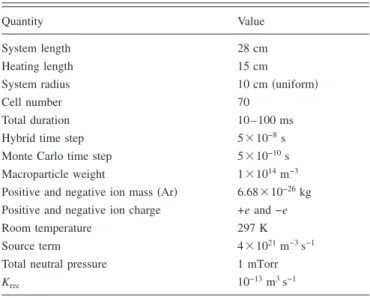
TABLE I. General parameters of the one-dimensional simulation of spon-taneous formation of propagating double layers. These parameters were used in the present investigation, unless stated otherwise.
Quantity Value
System length 28 cm
Heating length 15 cm
System radius 10 cm共uniform兲
Cell number 70
Total duration 10– 100 ms
Hybrid time step 5⫻10−8s
Monte Carlo time step 5⫻10−10s
Macroparticle weight 1⫻1014m−3
Positive and negative ion mass共Ar兲 6.68⫻10−26kg
Positive and negative ion charge +e and −e
Room temperature 297 K
Source term 4⫻1021m−3s−1
Total neutral pressure 1 mTorr
Krec 10−13m3s−1
FIG. 6.共Color online兲 Self-consistent spontaneous for-mation of propagating double layers in an electronega-tive discharge.共a兲 Snapshot of the plasma potential pro-file presenting a clear drop of⬃5 V; 共b兲 snapshot of the corresponding electron temperature profile, also pre-senting a drop;共c兲 snapshot of the electron 共solid line兲, positive ion 共dashed line兲 and negative ion 共dotted-dashed line兲 density profiles; 共d兲 plasma potential as a function of space and time when the electronegative propagating double layers are formed.
共ⱗ20 cm兲, 共iii兲 sufficiently high SF6concentration共ⲏ15%兲, and共iv兲 low gas pressure 共ⱗ5 mTorr兲. Static electronegative
double layers similar to those of Plihon et al.22 were not
found in the simulation.
V. PARAMETRIC STUDY OF DOUBLE LAYERS
For the sake of simplicity, rather than coupling the two submodels as was previously done, a temperature profile
Te共x兲 similar to that obtained self-consistently is now used as
a parameter of the simulations共the electron Monte Carlo is
deactivated兲 in order to perform a more systematic paramet-ric investigation of the spontaneous propagating double lay-ers. By integrating the ionization and attachment cross sec-tions over a Maxwellian distribution, the fits for the attachment and ionization rate coefficients52and for the cor-responding space-dependent ionization and attachment fre-quencies iz关Te共x兲兴 and att关Te共x兲兴 are found. The
tempera-ture profile decreases smoothly from 4.5 eV in the source to 3 eV in the diffusion chamber. Note that the temperature profile was only used to calculate the various reaction fre-quencies共ionization and attachment兲: the average over space of this temperature profile was used in the Boltzmann rela-tion关Eq.共1兲兴.
The effect of almost every parameter such as the positive and negative ion masses, the concentration of SF6, the sys-tem dimensions共length and radius兲, the temperature profile, etc., was investigated; the most relevant are reported here. Numerical parameters, such as the spatial resolution of the grid and the time step, were varied without significantly af-fecting the results.
A. Double layers form at low pressure with high attachment and recombination
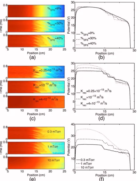
Figure7共a兲shows a spatiotemporal representation of the
plasma potential profiles and Fig. 7共b兲 shows snapshots of
the plasma potential profiles as a function of space for vari-ous concentrations of SF6. Propagating double layers do not form unless the relative concentration of SF6 is sufficiently large共ⲏ30% under the present conditions兲, confirming that a minimal electronegativity is required. As it was already men-tioned, static electronegative double layers similar to that of Plihon et al.22were not found in the simulation.
When the real EEDF is calculated by the simulation 共Sec. IV兲, the minimal relative concentration of SF6required for the formation of propagating double layers共i.e., to reach sufficient electronegativity兲 is ⬃15%. In the present case,
FIG. 7.共Color online兲 Contour plots of the plasma po-tential profiles as a function of space and time, and snapshots of the plasma potential profiles, for various relative concentrations of SF6关共a兲 and 共b兲兴,
recombina-tion rate coefficients关共c兲 and 共d兲兴, and neutral gas pres-sures关共e兲 and 共f兲兴.
when the EEDF is assumed to be Maxwellian, almost twice
this concentration共ⲏ30%兲 is required to observe the
propa-gating double layers. A reason for this is presumably that the EEDF calculated by the Monte Carlo submodel was not
Maxwellian 共high-energy depletion and low-energy
popula-tion兲 favoring attachment to ionization, leading to sufficient electronegativity for the formation of propagating double layers. This peculiar EEDF is not captured when assuming Maxwell-Boltzmann electrons; thus, the concentration of SF6 has to be increased accordingly in order to reach sufficient electronegativity, compatible with the double layers. This provides further evidence supporting the fact that the EEDF is a rather important parameter in the formation of electrone-gative double layers.
Figure 7共c兲 shows the plasma potential profiles as a
function of space and time, while Fig.7共d兲shows snapshots
of the plasma potential profiles as a function of space for various recombination rate coefficients Krec. The electrone-gativity is maintained constant by changing the relative con-centration of SF6accordingly. For the range of Krec investi-gated, the double-layer potential drop increases with Krec. For similar electronegativities, propagating double layers are only observed for sufficiently high attachment and recombi-nation. This is in good agreement with previously simulated electronegative double layers.26,28
The total neutral gas pressure was varied from 0.1 to 10 mTorr, keeping the relative concentrations of argon
and SF6 constant. Figures 7共e兲 and 7共f兲 show that above a
critical pressure共ⲏ5 mTorr兲 no double layer was formed.
To summarize this subsection, it should be remembered that propagating double layers were only observed at low pressure and for sufficiently high electronegativity obtained with high attachment and high recombination. This allows the existence of relatively cold negative ions, compatible with electronegative double layers.28
B. Small-diameter and long chambers are propitious to the formation of double layers
As mentioned in Sec. IV, propagating double layers were only observed when the radius of the chamber was relatively small and when the heating mechanism was localized to the source region. However, the geometric transition between the source region and the diffusion chamber does not seem to be
a fundamental parameter in neither the experiment23 or the
simulation, as in both cases it was possible to form double layers. Nevertheless, the strength of the double layers was observed to be enhanced by the presence of a geometric tran-sition.
Increasing the relative length of the diffusion chamber
FIG. 8.共Color online兲 Propagating double layers in an Ar/ SF6mixture, with an SF6relative concentration of
40% at 1 mTorr.共a兲 3D mapping of the plasma poten-tial profile as a function of space and time.共b兲 Contour plot of the plasma potential profile as a function of space and time, increased brightness indicates de-creased potential.共c兲 Snapshot of the plasma potential profile showing successive double layers, propagating from the diffusion chamber共right兲 to the source 共left兲. 共d兲 Snapshots of the electron 共solid line兲, positive 共dashed line兲 and negative 共dotted-dashed line兲 ion den-sity profiles. 共e兲 Snapshot of the electronegativity ␣ = n−/ neprofile.共f兲 Snapshots of ionization 共solid line兲, attachment 共dashed line兲 and recombination 共dotted-dashed line兲 source term profiles.
leads to an increase in the number of propagating double layers simultaneously present in the system, while reducing it leads to a decrease of the number of propagating double layers. When the diffusion chamber length is sufficiently de-creased, no propagating double layer forms. This is also very much aligned with the experimental results showing that the number of propagating double layers decreases and
eventu-ally reaches zero when the movable end plate 共Fig. 1兲 is
pushed towards the source.
C. Characterization of the propagating double layers
Figure8 shows various characteristics of typical propa-gating double layers for an SF6concentration of 40%. Figure
8共a兲is a three-dimensional共3D兲 mapping of the plasma
po-tential as a function of time and space. Although the present double layers propagate in the opposite direction, they ap-pear to be a phenomenon very similar to that observed by Plihon et al.,23as discussed later.
Figure 8共b兲 is a contour plot over 5 ms of the plasma
potential profile. As can be observed, the double layers al-ways form at the same critical position and propagate
to-wards the source at⬃100 m/s. Note that the simulation was
run up to 100 ms without any major variation.
Figures8共c兲and8共d兲are snapshots of the plasma poten-tial and the electron, positive, and negative ion densities. At the position of each double layer, a region of positive and negative ion rarefaction can be observed. Figure8共e兲shows a snapshot of the electronegativity␣= n−/ neat the same instant
and the electronegativity is minimal at the positions of the double layers, but maximal immediately downstream. The regions of high electronegativity are trapped between two successive double layers, and are pushed towards the source by the moving double layers, which is very much aligned with the experiment, as shown in Fig.3.
Figure8共f兲shows the ionization共solid line兲, attachment 共dashed line兲, and recombination 共dotted-dashed兲 source term profiles. The source is ionization-dominated, while the diffusion chamber is attachment dominated. The
recombina-tion takes place mostly in the source, but also in the high-electronegativity regions, where the ion densities are maxi-mum.
Figure 9 shows a low-frequency activity around
2 – 4 kHz in the downstream plasma 共i.e., where the double
layers are observed兲. This activity corresponds to the train of propagating double layers born at some critical downstream position and propagating towards the source. In the range of pressures investigated, the frequency of the propagating double layers was found to be weakly dependent on the neu-tral gas pressure.
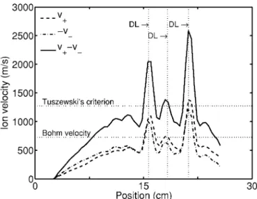
Figure10shows a snapshot of the positive and negative
ion average velocities:v+and −v−. The average downstream ion sound speed is shown by the lower horizontal line. At the positions of the propagating double layers, shown by the vertical lines, both positive and negative ions reach the
sound speed 共as derived by Braithwaite and Allen48 and
Franklin and Snell49兲 before entering the double layers from the high- and low-potential sides, respectively. The ions are then accelerated through the double layers. This shows that the Bohm criterion is verified for both positive and negative ions at the entrance of each double layer.
In addition, the propagating double layers observed in both the experiment and the simulation share many
proper-ties 共in the kHz range, propagation at ⬃100 m/s, a few
mTorr, etc.兲 with the downstream instability observed by Tuszewski et al.36and Tuszewski and Gary.37Although they have not explicitly measured a double layer, Tuszewski et
al.,36 have observed that the plasma immediately
down-stream of the critical position, where the downdown-stream insta-bility seems to be born, was transiently electropositive, sug-gesting the existence of an internal sheath; i.e., a double
layer. Tuszewski and Gary37 showed that the downstream
FIG. 10. Snapshot of the positive and negative ion average velocitiesv+,
−v−共broken lines兲 and the relative drift velocity v+−v−共solid line兲, as a
function of position. The vertical dotted lines show the positions of the double layers, while the horizontal lines show the Bohm velocity and “Tuszewski’s criterion.”
mal drift velocity required between positive and negative ions in order to get two-stream instability关Eq. 共15兲 in Ref.
37兴. Interestingly, this criterion is verified at the position of
each propagating double layer.
Note that it was shown by McKenzie50 that the Bohm
criterion and Tuszewski’s criterion are actually equivalent when the mass and the number of charges of the positive and negative ions are the same.
VI. PROPOSED MECHANISM FOR THE FORMATION OF PROPAGATING DOUBLE LAYERS
The correlation of the data presented here allows to pro-pose a mechanism for the formation of propagating double layers.
Propagating double layers are only observed 共with the
fully self-consistent simulation, Sec. IV兲 when a chamber of small diameter共no need of geometric transition兲 is combined with a localized heating mechanism共in the source region for example, from 0 to 15 cm兲. Electron radial loss due to the
small diameter has presumably three main effects. 共i兲 The
first and most obvious, observed under the present conditions of pressure共low pressure兲 is a depletion of the electron en-ergy distribution function at energies higher than the plasma potential 共Ref. 21, and references therein兲. As the depleted
part of the distribution also corresponds to the ionizing elec-trons, this effect tends to decrease ionization. In response, the electron temperature共of the Maxwellian portion of the elec-tron distribution兲 tends to increase to “boost” the ionization,
to counterbalance the radial loss, and to maintain the plasma 共fixed power兲.
共ii兲 The second effect of the electron radial loss, some-what related to the first one, appears in particular when radial loss is combined with the localized heating mechanism. In such a case the electron temperature increases more in the heating region than in the rest of the discharge, hence leading to a nonuniformity of the electron temperature, with a higher temperature in the source than in the diffusion chamber. As a result of the electron temperature decrease, the source is
ion-ization dominated 共high temperature favoring ionization to
attachment兲, while the diffusion chamber is
attachment-dominated共lower temperature favoring attachment to
ioniza-tion兲.
共iii兲 The third consequence of the electron radial loss
becomes clear when combined with the
ionization-dominated source. A significant fraction of the electrons cre-ated in the source are radially lost before being able to “fill up” the diffusion chamber, hence leading to a electron den-sity profile and the associated plasma potential profile both decreasing from the source to the diffusion chamber.
To summarize, positive ions are essentially created in the source while negative ions are essentially created in the diffusion chamber. Due to the decrease of the plasma poten-tial from the source to the diffusion chamber, positive and negative ions fall towards the diffusion chamber and the source, respectively. In other words, there exists two charged species drifting in opposite direction. For sufficiently
TABLE II. Experimental and simulated propagating double layers.
Parameters Experiment Simulation
Percent SF6 13%–25% 15%a
Krec Not a parameter Criticalb
Pc ⬃5 mTorr ⬃5 mTorr
Expansion Not critical Not critical
Small diameter Not known Criticald
Chamber lengthe Critical Critical
Properties Experiment Simulation
Frequency ⬃ kHz ⬃2 kHz Velocity 150 m / s 100 m / s Direction → ← ␣f ⬃4 4–6 Potential drop 7 Vg 5 Vh Tup/ Tdown 5 / 3.5 eVi 5 / 3.5 eV
Bohm criterionj Not known Satisfied
aMinimal concentration allowing the formation of double layers in the simulation: 15% with fully
self-consistent model; 30% when Boltzmann electrons are assumed.
bThe simulation showed that DLs were formed only for sufficiently large recombination rate. DLs were
ob-served in the simulation for realistic recombination rates共Krec= 10−13m3s−1兲. cPressure P above which no double layer was formed.
dNo double layer observed for large-diameter chambers.
eSufficiently short diffusion chambers prevent the formation of double layers.
fMaximum of the electronegativity␣obtained just downstream of the double layers. Measured via
photode-tachment for the experimental values. The error bar is +100% and −20% for the experimental data.
g7 V at the potential discontinuity, almost 10 V in total.
h5 V with the fully self-consistent model, 2 V when Boltzmann electrons are assumed. iTemperatures reported for the stable double layer.
long reactors, each species eventually reaches the Bohm ve-locity, breaking down the quasineutrality of the plasma and leading to the formation of an internal sheath共i.e., a double layer兲.
With such a mechanism, there is no reason that the formed double layers should remain in place as the system is highly nonsymmetrical; however, the reason the double lay-ers propagate in one direction or the other remains unclear. We can postulate that because of a small charge unbalance within the double layers, there exists an internal force push-ing them. Note that another mechanism should be sought for the stable double layer also observed by Plihon et al.22
VII. CONCLUSION
The propagating double layers were experimentally characterized and the window of parameters, such as the neu-tral gas pressure, the relative concentration of SF6, the input power, etc., for which they form was fully determined in Ref.
23. The propagating double layers spontaneously forming in
the self-consistent simulation were shown to be a very simi-lar phenomenon to that observed experimentally. The main features of the propagating double layers observed
experi-mentally and in the simulation are summarized in TableII.
Despite the fact that these propagating double layers do not propagate in the same direction, they share many properties, such as their velocity of propagation, frequency, electronega-tivity, temperature drop, etc. In addition, they appear under very similar conditions, such as neutral gas pressure, relative SF6concentration, etc.
The simulation gave evidence supporting the observation that double layers form spontaneously in electronegative plasmas and allowed us to propose a formation mechanism
by correlating the following observations. 共i兲 To observe
propagating double layers, both the experiment and the simu-lation have shown that a lower limit to the electronegativity is required, which is achieved thanks to a sufficient relative
concentration of SF6 and sufficient attachment. 共ii兲 The
losses in volume of both positive and negative ions via re-combination also appear to be crucial. The simulation showed that below a critical recombination rate, no double
layer could be formed. 共iii兲 The simulation also confirmed
that the geometry of the chamber, i.e., a change in diameter,
does not seem to be a critical parameter. 共iv兲 However, the
diameter itself is crucial, since it can dramatically change the electron energy distribution function that controls ionization
and attachment and therefore the electronegativity. 共v兲 The
simulation showed that for chambers below a certain length, no double layer could be sustained, which is in good agree-ment with the experiagree-mental observations. This may well be because positive and negative charges need to develop a suf-ficient relative drift velocity, which can be achieved only in sufficiently long chambers.共vi兲 Finally, the neutral gas pres-sure is also a fundamental parameter, as no double layer was
observed for pressure above⬃5 mTorr.
As a concluding remark, it may be noted that the
propa-1M. A. Raadu, Phys. Rep. 178, 25共1989兲. 2I. Langmuir, Phys. Rev. 33, 954共1929兲.
3P. C. Stangeby and J. E. Allen, J. Phys. D 6, 224共1973兲.
4N. Sato, G. Popa, E. Märk, E. Mravlag, and R. Schrittwieser, Phys. Fluids
19, 70共1976兲.
5P. Coakley, N. Hershkowitz, R. Hubbard, and G. Joyce, Phys. Rev. Lett.
40, 230共1978兲.
6C. Charles and R. W. Boswell, Appl. Phys. Lett. 82, 1356共2003兲. 7H. Alfvén, Tellus 10, 104共1958兲.
8R. D. Albert and P. J. Lindstrom, Science 170, 1398共1970兲.
9M. Temerin, K. Cerny, W. Lotko, and F. S. Mozer, Phys. Rev. Lett. 48,
1175共1982兲.
10H. Alfvén and P. Carlqvist, Sol. Phys. 1, 220共1967兲.
11R. W. Boswell, E. Marsch, and C. Charles, Astrophys. J. 640, L199
共2006兲.
12S. A. Cohen, N. S. Siefert, S. Stange, E. E. Scime, and F. M. Levinton,
Phys. Plasmas 10, 2593共2003兲.
13O. Sutherland, C. Charles, N. Plihon, and R. W. Boswell, Phys. Rev. Lett.
95, 205002共2005兲.
14A. M. Keesee, E. E. Scime, C. Charles, A. Meige, and R. W. Boswell,
Phys. Plasmas 12, 093502共2005兲.
15A. Aanesland, C. Charles, M. A. Lieberman, and R. W. Boswell, Phys.
Rev. Lett. 97, 075003共2006兲.
16N. Plihon, P. Chabert, and C. Corr, Phys. Plasmas 14, 013506共2007兲. 17M. A. Lieberman and C. Charles, Phys. Rev. Lett. 97, 045003共2006兲. 18A. Meige, R. W. Boswell, C. Charles, J.-P. Boeuf, G. J. M. Hagelaar, and
M. M. Turner, IEEE Trans. Plasma Sci. 33, 334共2005兲.
19A. Meige, R. W. Boswell, C. Charles, and M. M. Turner, Phys. Plasmas
12, 052317共2005兲.
20X. Sun, A. M. Keesee, C. Biloiu, E. E. Scime, A. Meige, C. Charles, and
R. W. Boswell, Phys. Rev. Lett. 95, 025004共2005兲.
21A. Meige and R. W. Boswell, Phys. Plasmas 13, 092104共2006兲. 22N. Plihon, C. S. Corr, and P. Chabert, Appl. Phys. Lett. 86, 091501
共2005兲.
23N. Plihon, C. S. Corr, P. Chabert, and J.-L. Raimbault, J. Appl. Phys. 98,
023306共2005兲.
24I. G. Kouznetsov, A. J. Lichtenberg, and M. A. Lieberman, J. Appl. Phys.
86, 4142共1999兲.
25T. E. Sheridan, J. Phys. D 32, 1761共1999兲.
26T. E. Sheridan, P. Chabert, and R. W. Boswell, Plasma Sources Sci.
Technol. 8, 457共1999兲.
27T. E. Sheridan, N. S. J. Braithwaite, and R. W. Boswell, Phys. Plasmas 6,
4375共1999兲.
28P. Chabert and T. E. Sheridan, J. Phys. D 33, 1854共2000兲. 29J.-P. Boeuf, Phys. Rev. A 36, 2782共1987兲.
30R. W. Boswell, Phys. Lett. 33A, 457共1970兲.
31A. Cantin and R. R. J. Gagne, Appl. Phys. Lett. 30, 316共1977兲. 32M. B. Hopkins and W. G. Graham, Rev. Sci. Instrum. 57, 2210共1986兲. 33F. M. J. Gudmundsson, Tech. Rep., Science Institute University of Iceland,
2002.
34M. Bacal, Rev. Sci. Instrum. 71, 3981共2000兲.
35M. Tuszewski and R. R. White, J. Appl. Phys. 94, 2858共2003兲. 36M. Tuszewski, R. R. White, and G. A. Wurden, Plasma Sources Sci.
Technol. 12, 396共2003兲.
37M. Tuszewski and S. Gary, Phys. Plasmas 10, 539共2003兲.
38R. W. Hockney and J. W. Eastwood, Computer Simulation Using Particles
共IOP, Bristol, 1988兲.
39C. K. Birdsall and A. B. Langdon, Plasma Physics via Computer
共McGraw-Hill, New York, 1985兲.
40A. Meige, Ph.D. thesis, The Australian National University共Canberra兲 and
Université Paul Sabatier共Toulouse兲, 2006.
41W. H. Press, S. A. Teukolsky, W. T. Vetterling, and B. P. Flannery,
Nu-merical Recipes in C: The Art of Scientific Computing共Cambridge
Uni-versity Press, Cambridge, 1992兲.
42G. J. M. Hagelaar, “How to normalize the density of Boltzmann electrons
in a transient self-consistent plasma model”共unpublished兲.
43L. Garrigues, A. Heron, J. C. Adam, and J. P. Boeuf, Plasma Sources Sci.
Technol. 9, 219共2000兲.
44P. L. G. Ventzek, T. J. Sommerer, R. J. Hoekstra, and M. J. Kushner, Appl.
47C. M. Ferreira, G. Gousset, and M. Touzeau, J. Phys. D 21, 1403共1988兲. 48N. S. J. Braithwaite and J. E. Allen, J. Phys. D 21, 1733共1988兲. 49R. N. Franklin and J. Snell, J. Phys. D 25, 453共1992兲. 50J. F. McKenzie, J. Plasma Phys. 65, 181共2001兲.
51Here, the term “temperature” is used loosely, as the EEDF may not be
Maxwellian. What is meant by “temperature” is “the temperature that would have a Maxwellian distribution with the same mean energy.”
52Reaction rate coefficients k can generally be well fitted by a generalized
Arrhenius function of the temperature Te, of the form k共Te兲=exp共a + b ln Te+ c / Te+ d / Te2+ e / Te3兲.