HAL Id: ensl-00356421
https://hal-ens-lyon.archives-ouvertes.fr/ensl-00356421
Submitted on 27 Jan 2009
HAL is a multi-disciplinary open access
archive for the deposit and dissemination of
sci-entific research documents, whether they are
pub-lished or not. The documents may come from
teaching and research institutions in France or
abroad, or from public or private research centers.
L’archive ouverte pluridisciplinaire HAL, est
destinée au dépôt et à la diffusion de documents
scientifiques de niveau recherche, publiés ou non,
émanant des établissements d’enseignement et de
recherche français ou étrangers, des laboratoires
publics ou privés.
Large multipliers with less DSP blocks
Florent de Dinechin, Bogdan Pasca
To cite this version:
Florent de Dinechin, Bogdan Pasca. Large multipliers with less DSP blocks. Field Programmable
Logic and Applications, Aug 2009, Czech Republic. �ensl-00356421�
Large multipliers with less DSP blocks
LIP research report RR2009-03
Florent de Dinechin, Bogdan Pasca
∗LIP (CNRS/INRIA/ENS-Lyon/UCBL)
´
Ecole Normale Sup´erieure de Lyon — Universit´e de Lyon
[email protected]
Abstract
Recent computing-oriented FPGAs feature DSP blocks including small embedded multipliers. A large integer multiplier, for instance for a double-precision floating-point multiplier, consumes many of these DSP blocks. This article studies three non-standard implementation techniques of large multipliers: the Karatsuba-Ofman al-gorithm, non-standard multiplier tiling, and specialized squarers. They allow for large multipliers working at the peak frequency of the DSP blocks while reducing the DSP block usage. Their overhead in term of logic resources, if any, is much lower than that of emulating embedded multipliers. Their latency overhead, if any, is very small. Complete algorithmic descriptions are provided, carefully mapped on recent Xilinx and Altera devices, and validated by synthesis results.
1
Introduction
A paper-and-pencil analysis of FPGA peak floating-point performance [8] clearly shows that DSP blocks are a rel-atively scarse resource when one wants to use them for acclerating double-precision (64-bit) floating-point appli-cations.
This article presents techniques reducing DSP block us-age for large multipliers. Here, “large” means: any mul-tiplier that, when implemented using DSP blocks, con-sumes more than two of them, with special emphasis on
∗This work was partly supported by the XtremeData university pro-gramme and the ANR EVAFlo and TCHATER projects.
the multipliers needed for single-precision (24-bit) and double-precision (53-bit) floating-point.
There are many ways of reducing DSP block usage, the simplest being to implement multiplications in logic only. However, a LUT-based large multiplier has a large LUT cost (at leastn2
LUTs forn-bit numbers, plus the flip-flops for pipelined implementations). In addition, there is also a large performance cost: a LUT-based large mul-tiplier will either have a long latency, or a slow clock. Still, for some sizes, it makes sense to implement as LUTs some of the sub-multipliers which would use only a frac-tion of a DSP block.
We focus here on algorithmic reduction of the DSP cost, and specifically on approaches that consume few additional LUTs, add little to the latency (and sometime even reduce it), and operate at a frequency close to the peak DSP frequency.
All the results in this article have been obtained using ISE 9.2i / LogiCore Multiplier 10.0.
Contributions
After an introduction in Section 2 to the implementation large multipliers in DSP-enhanced FPGAs, this article has three distinct contributions.
Section 3 studies the Karatsuba-Ofman algorithm [5, 6, 7], commonly used1 in multiple-precision software and,
on FPGAs, large multiplication in finite fields. This algo-rithm trades multiplications for additions, thus reducing
1We were surprised to find no reference to Karatsuba-Ofman for in-teger multiplication in the FPGA literature and will be deeply grateful to the referees for any pointer to prior work on FPGAs.
the DSP cost of large multipliers from 4 to 3, from 9 to 6, or from 16 to 10. This technique works for any DSP-enhanced FPGA from Xilinx or Altera, but is actually less efficient on more recent chips, which are less flexible.
Section 4 introduces a tiling-based technique that widens the multiplier design space on Virtex-5 (or any cir-cuit featuring rectangular multipliers). It is illustrated by two original multipliers, a 41-bit one in 4 DSP48E and a 58-bit one in 8 DSP48E, suitable for double-precision.
Finally, Section 5 focuses on the computation of squares. Squaring is fairly common in FPGA-accelerated computations, as it appears in norms, statistical compu-tations, polynomial evaluation, etc. A dedicated squarer saves as many DSP blocks as the Karatsuba-Ofman algo-rithm, but without its overhead.
For each of these techniques, we present an algorith-mic description followed by a discussion of the match to DSP blocks of relevant FPGA devices, and experimental results.
2
Context and state of the art
2.1
Large multipliers using DSP blocks
Letk be an integer parameter, and let X and Y be 2k-bit integers to multiply. We will write them in binaryX = P2k−1 i=0 2 ix iandY =P2k−1i=0 2 iy i.
Let us now split each ofX and Y into two subwords of k bit each:
X = 2kX
1+ X0 and Y = 2kY1+ Y0
X1is the integer formed by thek most significant bits of
X, and X0is made of thek least significant bits of X.
The productX × Y may be written X × Y = (2kX
1+ X0) × (2kY1+ Y0)
or
XY = 22kX
1Y1+ 2k(X1Y0+ X0Y1) + X0Y0 (1)
This product involves 4 sub-products. Ifk is the input size of an embedded multiplier, this defines an architecture for the2k multiplication that requires 4 embedded multipli-ers. This architecture can also be used for any input size betweenk + 1 and 2k. Besides, it can be generalized: For
anyp > 1, numbers of size between pk − k + 1 and pk may be decomposed intop k-bit numbers, leading to an architecture consumingp2
embedded multipliers. Earlier FPGAs had only embedded multipliers, but the more recent DSP blocks [10, 9, 1, 2] include internal adders designed in such a way that most of the additions in Equation (1) can also be computed inside the DSP blocks. Let us now review these features in current mainstream architectures, focussing on the capabilities of the DSP blocks relevant to this paper.
2.2
Overview of DSP block architectures
The Virtex-4 DSP block (DSP48) contains one signed 18x18 bit multiplier followed by a 48-bit addi-tion/subtraction unit [10]. As the multiplier decompo-sition (1) involves only positive numbers, the multipli-ers must be used as unsigned 17-bit multiplimultipli-ers, so for these devices we will havek = 17. The multiplier output may be added to the output of the adder from the previ-ous DSP48 in the row (using the dedicated PCOUT/PCIN port), possibly with a fixed 17-bit shift – this allows for 217
factors as in Equation (1).
In Virtex-5 DSP blocks (DSP48E), the 18x18 multipli-ers have been replaced with asymmetrical ones (18x25 bits signed). This reduces the DSP cost of floating-point single-precision (24-bit significand) from 4 to 2. The fixed shift on PCIN is still 17-bit only [9]. Another im-provement is that the addition unit is now capable of adding a third term coming from global routing.
The Stratix II DSP block consists of four 18x18 multi-pliers which can be used independently. It also includes two levels of adders, enabling the computation of a com-plete 36x36 product or a comcom-plete 18-bit complex prod-uct in one block [1]. With respect to this article, the main advantage it has over the Virtex-4 is the possibility to op-erate on unsigned 18-bit inputs: Altera devices may use k = 18, which is an almost perfect match for double-precision (53-bit significand) as54 = 3 × 18.
In Stratix III, the previous blocks are now called half-DSP blocks and are grouped by two [2]. A half-half-DSP block contains 4 18x18 multipliers, 2 36-bit adders and one 44-bit adder/accumulator, which can take its input from the half-DSP block just above. This direct link en-ables in-DSP implementation of some of the additions of (1). Unfortunately, the Stratix-III half-DSP is much less
38
72 55
37 37
Figure 1: Stratix-III and IV operating modes using four 18x18 multipliers. Each rectangle is the 36-bit output of an 18x18 multiplier. All constant shifts are multiples of 18 bits.
flexible than the Stratix-II DSP. Indeed, its output size is limited, meaning that the 36x36 multiplier of a half-DSP may not be split as four independent 18x18 multipliers. More precisely, the four input pairs may be connected in-dependently, but the output is restricted to one of the ad-dition patterns described by Figure 1. The Stratix IV DSP block is mostly identical to the Stratix III one.
All these DSP blocks also contain dedicated regis-ters that allow for pipelined designed at high frequencies (from 300 to 600 MHz depending on the generation).
3
Karatsuba-Ofman algorithm
3.1
Two-part splitting
The classical step of Karatsuba-Ofman algorithm is the following. First computeDX = X1−X0andDY = Y1−
Y0. The results are signed numbers that fit onk + 1 bits2.
Then compute the productDX× DY using a DSP block.
Now the middle term of equation (1),X1Y0+ X0Y1, may
be computed as:
X1Y0+ X0Y1= X1Y1+ X0Y0− DXDY (2)
Then, the computation of XY using (1) only requires three DSP blocks: one to computeX1Y1, one forX0Y0,
and one forDXDY.
There is an overhead in terms of additions. In princi-ple, this overhead consists of twok-bit subtractions for computingDXandDY, plus one2k-bit addition and one
2k-bit subtraction to compute equation (2). There are still more additions in equation (1), but they also have to be
2There is an alternative Karatsuba-Ofman algorithm computing X1+X0 and Y1+Y0. We present the subtractive version, because it enables to use the Xilinx 18-bit signed-only multipliers fully, while working on Altera chips as well.
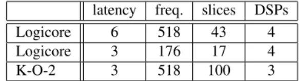
latency freq. slices DSPs Logicore 6 518 43 4 Logicore 3 176 17 4 K-O-2 3 518 100 3
Table 1: 34x34 multipliers on Virtex-4 (4vlx15sf363-12)
computed by the classical multiplication decomposition, and are therefore not counted in the overhead.
Counting one LUT per adder bit3, and assuming that
thek − bit addition in LUT can be performed at the DSP operating frequency, is we get a theoretical overhead of 6k LUT. However, the actual overhead is difficult to pre-dict exactly, as it depends on the scheduling of the various operations, and in particular in the way we are able to ex-ploit registers and adders insided DSPs. There may also be an overhead in terms of latency, but we will see that the initial subtraction latency may be hidden, while the addi-tional output additions may take the place of the saved multiplier.
At any rate, these overheads are much smaller than the overheads of emulating one multiplier with LUTs at the peak frequency of the DSP blocks. Let us now illus-trate this discussion with a practical implementation on a Virtex-4.
3.2
Implementation issues on Virtex-4
The fact that the differencesDXandDY are now signed
18-bit is actually a perfect match for a Virtex-4 DSP block.
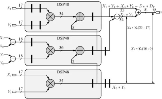
Figure 2 presents the architecture chosen for imple-menting the previous multiplication on a Virtex-4 device. The shift-cascading feature of the DSPs allows the com-putation of the right-hand side of equation (2) inside the three DSPs at the cost of a 2k-bit subtraction needed for recovering X1Y1. Notice that here, the pre-subtractions
do not add to the latency.
This architecture was described in VHDL (using + and * from the ieee.std_logic_arith package), tested, and synthesized. The corresponding results are given in Table 1. Some tweaking of the options was
3In all the following we will no longer distinguish additions from subtractions, as they have the same LUT cost in FPGAs.
Y1 X1 z X0 X1 Y0 Y1 z X0 Y0 DSP48 DSP48 DSP48 P X0∗ Y0 51 68 X0∗ Y0(16 : 0) X1∗ Y1 X1∗ Y1+ X0∗ Y0− DX∗ DY X0∗ Y0(33 : 17) 17 17 17 17 18 18 34 36 34 34 35
Figure 2: 34x34bit multiplier using Virtex-4 DSP48
needed, for instance to prevent using the much slower SRL16 to implement the registers.
3.3
Three-part splitting
Now consider two numbers of size 3k, decomposed in three subwords each:
X = 22kX 2+2kX1+X0 and Y = 22kY2+2kY1+Y0 We have XY = 24kX 2Y2 + 23k(X 2Y1+ X1Y2) + 22k(X 2Y0+ X1Y1+ X0Y2) + 2k(X 1Y0+ X0Y1) + X0Y0 (3) After precomputingX2− X1,Y2− Y1,X1− X0,Y1−
Y0,X2− X0,Y2− Y0, we compute (using DSP blocks)
the six products
P22= X2Y2 P21= (X2− X1) × (Y2− Y1)
P11= X1Y1 P10= (X1− X0) × (Y1− Y0)
P00= X0Y0 P20= (X2− X0) × (Y2− Y0)
and equation (3) may be rewritten as XY = 24kP 22 + 23k(P 22+ P11− P21) + 22k(P 22+ P11+ P00− P20) + 2k(P 11+ P00− P10) + P00 (4)
latency freq. slices DSPs LogiCore 11 518 156 9 LogiCore 6 264 94 9 K-O-3 6 340 337 6
Table 2: 51x51 multipliers on Virtex-4 (4vlx15sf363-12).
Here we have reduced DSP usage from 9 to 6 which, ac-cording to Montgomery [7], is optimal. There is a first overhead of6k LUTs for the pre-subtractions (again, each DSP is traded for2k LUTs). Again, the overhead of the remaining additions is difficult to evaluate. Most may be implemented inside DSP blocks. However, as soon as we need to use the result of a multiplication twice (which is the essence of Karatsuba-Ofman algorithm), we can no longer use the internal adder behind this result, so LUT cost goes up. Table 2 provides some synthesis results. The critical path is in one of the2k-bit additions, and could be reduced by pipeling them.
3.4
Four-part splitting and more
We present this last section for completeness, but it is probably less useful: The most recent FPGA families by Xilinx and Altera do not need it for an efficient implemen-tation of double-precision multiplication. 3-part splitting is enough thanks to unsigned 18-bit multiplication on Al-tera, using 9 or 6 DSP blocks depending on Karatsuba al-gorithm or not. On Virtex-5, the multiplier structure pre-sented in Section 4 consumes only 8 or 9 DSP48E.
Classically, the Karatsuba idea may be applied recur-sively: A 4-part splitting is obtained by two levels of 2-part splitting. However, a direct expression allows for a more straightforward implementation. From
X = 23kX
3+ 22kX2+ 2kX1+ X0
Y = 23kY
we have XY = 26kX 3Y3 + 25k(X 2Y3+ X3Y2) + 24k(X 3Y1+ X2Y2+ X1Y3) + 23k(X 3Y0+ X2Y1+ X1Y2+ X0Y3) + 22k(X 2Y0+ X1Y1+ X0Y2) + 2k(X 1Y0+ X0Y1) + X0Y0 (5)
Here we compute (using DSP blocks) the products P33= X3Y3 P22= X2Y2 P11= X1Y1 P00= X0Y0 P32= (X3− X2) × (Y3− Y2) P31= (X3− X1) × (Y3− Y1) P30= (X3− X0) × (Y3− Y0) P21= (X2− X1) × (Y2− Y1) P20= (X2− X0) × (Y2− Y0) P10= (X1− X0) × (Y1− Y0)
and equation (5) may be rewritten as XY = 26kP 33 + 25k(P 33+ P22− P32) + 24k(P 33+ P22+ P11− P31) + 23k(P 33+ P00− P30 + P22+ P11− P21) + 22k(P 22+ P11+ P00− P20) + 2k(P 11+ P00− P10) + P00 (6) Here we have only 10 multiplications instead of 16. Note that the recursive variant saves one more multiplication: It precomputes
P3210= (X3+ X2+ X1+ X0) × (Y3+ Y2+ Y1+ Y0)
instead ofP30 and P21, and computes the middle term
X3Y0+ X2Y1+ X1Y2+ X0Y3of equation (5) as a sum
of P3210 and the other Pij. However this poses several
problems. Firstly, we have to use a smallerk (splitting in smaller chunks) to ensureP3210doesn’t overflow from the
DSP size. Secondly, we currently estimate that the saved DSP is not worth the critical path degradation.
A reader interested in even larger multipliers should read Montgomery’s study [7].
3.5
Issues with the most recent devices
The Karatsuba-Ofman algorithm is useful on Virtex-II to Virtex-4 as well as Stratix-II devices, to implement single and double precision floating-point.
The larger (36 bit) DSP block granularity (see Sec-tion 2.2) of Stratix-III and Stratix-IV prevents us from us-ing the result of a 18x18 bit product twice, as needed by the Karatsuba-Ofman algorithms. This pushes their rel-evance to multipliers classically implemented as at least four 36x36 half-DSPs. The additive version should be considered, as it may improve speed by saving some of the sign extensions. The frequency will be limited by the input adders if they are not pipelined or implemented as carry-select adders.
On Virtex-5 devices, the Karatsuba-Ofman algorithm can be used if each embedded multiplier is considered as a 18x18 one, which is suboptimal. For instance, single precision K-O requires 3 DSP blocks, where the classical implementation consumes 2 blocks only. We still have to find a variant of Karatsuba-Ofman that exploits the 18x25 multipliers to their full potential.X may be split in 17-bit chunks andY in 24-bit chunks, but then, in Equation (2), DX andDY are two 25-bit numbers, and their product
will require a 25x25 multiplier.
We now present an alternative multiplier design tech-nique specific to Virtex-5 devices.
4
Non-standard tilings
This section optimizes the use of the Virtex-5 25x18 signed multipliers. In this case,X has do be decomposed into 17-bit chunks, while Y is decomposed into 24-bit chunks. Indeed, in the Xilinx LogiCore Floating-Point Generator, version 3.0, a double-precision floating-point multiplier consumed 12 DSP slices:X was split into 3 24-bit subwords, whileY was split into 4 17-bit subwords. This splitting would be optimal for a 72x68 product, but quite wasteful for the 53x53 multiplication required for double-precision, as illustrated by Figure 3(a). In version 4.0, some of the smaller sub-multipliers have been ex-pressed as additions and replaced with either LUT logic or internal DSP adders (the details are not published), re-ducing the count to 9 or 10 DSP slices. However, a 53-bit integer multiplier in LogiCore 10 still consumes 12
DSP48E.
The following equation presents an original way of im-plementing double-precision (actually up to 58x58) mul-tiplication, using only eight 18x25 multipliers.
XY = X0:23Y0:16 (M1) + 217 (X0:23Y17:33 (M2) + 217(X 0:16Y34:57 (M3) + 217X 17:33Y34:57)) (M4) + 224(X 24:40Y0:23 (M8) + 217(X 41:57Y0:23 (M7) + 217(X 34:57Y24:40 (M6) + 217X 34:57Y41:57))) (M5) + 248X 24:33Y24:33 (7)
The reader may check that each multiplier is a 17x24 one except the last one. The proof that Equation (7) indeed computesX × Y consists in considering
X ×Y = ( 57 X i=0 2ixi)×( 57 X j=0 2jyj) = X i,j∈{0...57} 2i+jxiyj
and checking that each partial bit product 2i+jx iyj
ap-pears once and only once in the right-hand side of Equa-tion (7). This is illustrated by Figure 3(b).
The last line of Equation (7) is a 10x10 multiplier (the white square at the center of Figure 3(b)). It could con-sume an embedded multiplier, but is probably best imple-mented as logic.
Equation (7) has been parenthesized to make the best use of the DSP48E internal adders: we have two parallel cascaded additions with 17-bit shifts.
51 48
(a) standard tiling
34 0 0 24 41 58 34 17 41 24 17 M1 M2 M3 M4 M5 M6 M7 M8 (b) proposed tiling
Figure 3: 53-bit multiplication using Virtex-5 DSP48E. The dashed square is the 53x53 multiplication.
latency Freq. REGs LUTs DSPs LogiCore 14 655 348 297 12 LogiCore 8 337 297 222 12 LogiCore 4 115 137 34 12 Tiling 4 369 243 400 8
Table 3: 58x58 multipliers on Virtex-5 (5vlx30ff324-3). Results for 53-bits are almost identical. However, this table misses a serious contender: the multiplier used in LogiCore Floating-Point Operator 4.0, which is unfortu-nately not available separately as an integer multiplier
This design was implemented in VHDL, tested, and synthesized. Preliminary synthesis results are presented in Table 3. The critical path is in the final addition, cur-rently implemented as LUTs. It could probably exploit the 3-input addition capabilities of DSP48E instead. Or it could be pipelined to reach the peak DSP48E frequency, at the cost of one more cycle of latency. The LUT cost is also larger than expected, even considering that the 10x10 multiplier is implemented in LUTs and pipelined.
Figure 4 illustrates a similar idea for 41x41 and for 65x65 multiplications – the corresponding equations are left as an exercise to the reader. The 65x65 example (which may even be used up to 68x65) shows that a tiling doesn’t have to be regular.
41x41
65x65
5
Squarers
The bit-complexity of squaring is roughly half of that of standard multiplication. Indeed, we have the identity:
X2 = ( n−1X i=0 2ix i)2 = n−1 X i=0 22ix i + X 0<i<j<n 2i+1x i
This is is only useful if the squarer is implemented as LUTs. However, a similar property holds for a splitting of the input into several subwords:
(2kX 1+ X0)2= 22kX12+ 2 · 2 kX 1X0+ X02 (8) (22kX 2+ 2kX1+ X0)2 = 24kX22+ 2 2kX2 1+ X 2 0 + 2 · 23kX 2X1 + 2 · 22kX 2X0 + 2kX 1X0 (9) Computing each square or product of the above equation in a DSP block, there is again a reduction of the DSP count from 4 to 3, or from 9 to 6. Besides, this time, it comes at no arithmetic overhead.
5.1
Squarers on Virtex-4 and Stratix-II
Now consider k = 17 for a Virtex-4 implementation. Looking closer, it turns out that we still lose something using the above equations: The cascading input of the DSP48 and DSP48E is only able to perform a shift by 17. We may use it only to add terms whose weight differs by 17. Unfortunately, in equation (8) the powers are 0, 18 and 34, and in equation (9) they are 0, 18, 34, 35, 42, 64.
One more trick may be used for integers of at most 33 bits. Equation (8) is rewritten
(217 X1+ X0) 2 = 234 X2 1+ 2 17 (2X1)X0+ X 2 0 (10)
and2X1 is computed by shifting X1 by one bit before
inputting it in the corresponding DSP. We have this spare bit if the size ofX1is at most 16, i.e. if the size ofX is at
most 33. As the main multiplier sizes concerned by such techniques are 24 bit and 32 bit, the limitation to 33 bits is not a problem in practice.
Table 4 provides synthesis results for 32-bit squares on a Virtex-4. Such a squarer architecture can also be fine-tuned to the Stratix II-family.
5.2
Squarers on Stratix-III and Stratix-IV
On the most recent Altera devices, the 36-bit granular-ity means that the previous technique begins to save DSP blocks only for very large input sizes.
We now present an alternative way of implementing a double-precision (53-bit) squarer on such devices us-ing only two 36x36 half-DSPs, where a standard multi-plier requires four on a Stratix-III and two and a half on a Stratix-IV. It exploits the fact that, although the addition structure of the four 18x18 sub-multipliers is fixed, their inputs are independent.
The two 36x36 multipliers we need are illustrated on Figure 5. The upper-right one is completely standard and computes the subsquare X0:35X0:35. The
bottom-left one (labelled P ) is configured as a multiplier, too, but it doesn’t need to recompute and add the sub-product X18:35X18:35(the dark square in the center), which was
already computed by the previous multiplier. Instead, this sub-multiplier will complete the 53-bit square by com-puting2X0:17X36:53(the sum of the two white squares),
which has the same weight236
. To this purpose, the in-puts of the corresponding 18x18 sub-multiplier have to be set asX0:17and2X36:53. The latter will not overflow,
be-cause a double-precision significand product is 53x53 and not 54x54, therefore we haveX53= 0.
We have not yet validated this squarer experimentally. Compared to a standard multiplier, there should be no LUT increase.
Applied to a single 36x36 block, a similar technique allows us to compute squares up to 35x35 using only three of the four 18x18 blocks. The fourth block is unusable, but this may reduce power consumption.
latency frequency slices DSPs LogiCore 6 518 40 4 LogiCore 3 176 17 4 Squarer 3 268 20 3
5.3
Non-standard tilings on Virtex-5
Figure 6 ilustrates non-standard tilings for double-precision square using six or five 24x17 multiplier blocks. Remark that these tilings are symmetrical with respect to the diagonal, so that each symmetrical multiplication may be computed only once. However, there are slight overlaps on the diagonal: the darker squares are computed twice, and therefore the corresponding sub-product must be removed. These tilings are designed in such a way that all the smaller sub-products may be computed in LUTs at the peak DSP frequency.
The equations are therefore the following: X2 = X 0:16X0:16 (M1) + 234X 17:33:X17:33 (M2) + 272 X36:52X36:52 (M3) + 2 × 217 X0:16X17:35 (M4) + 2 × 219+34 X19:35X34:52 (M5) − 234+34X34:35X34:35 (LUT) + 2 × 236X 0:18X36:52 (M6) + 2 × 217+34X 17:18X34:35 (LUT) (11) X2 = X 0:16X0:18 (M1) + 217X 17:18X0:18 (LUT) + 248X 24:40:X24:40 (M2) + 2 × 217X 0:23X19:35 (M3) − 219+19X19:23X19:23 (LUT) + 2 × 236X 0:23X36:52 (M4) + 2 × 224+41 X24:47X41:52 (M5) − 241+41X41:47X41:47 (LUT) + 248+48 X48:52X48:52 (LUT) (12)
Note that a square multiplication on the diagonal of size n, implemented as LUT, should consume only n(n+1)/2 LUTs instead ofn2 thanks to symmetry. 36 0 0 36 X0:17X36:53 X36:53X0:17 X0:35X0:35 P
Figure 5: Double-precision squarer for Stratix-III and IV
36 53 17 0 M1 M2 M3 M5 M6 M4 0 41 24 0 19 36 53 M1 M2 M3 M4 M5
Figure 6: Double-precision squaring on Virtex-5. Left: tiling corresponding to Equation (11). Right: tiling corre-sponding to Equation (12).
We currently do not have implementation results. It is expected that implementing such equations will lead to a large LUT cost, partly due to the many sub-multipliers, and partly due to the irregular weights of each line (no 17-bit shifts) which may prevent optimal use of the internal adders of the DSP48E blocks.
6
Conclusion
This article has shown that precious DSP resources can be saved in several situations by exploiting the flexibility of the FPGA target. An original family of multipliers for Virtex-5 is also introduced, along with original squarer ar-chitectures. The reduction in DSP usage sometimes even entails a reduction in latency.We believe that the place of some of these algorithms is in vendor core generators and synthesis tools, where they will widen the space of imple-mentation trade-off offered to a designer.
The fact that the Karatsuba-Ofman technique is poorly suited to the larger DSP granularity of last-generation de-vices inspires some reflexions. The trend towards larger granularity, otherwise visible in the increase of the LUT complexity, is motivated by Rent’s law: Routing con-sumes a larger share of the resources in larger-capacity devices [3]. Another illustration is the top entry of the top 10 predictions4 for FFCMs in 2012: “FPGAs will
have floating point cores”. We hope this prediction will turn out to be wrong! Considering that GPUs already of-fer in 2009 massive numbers of floating-point cores, we believe that FPGAs should go further on their own way, which has always been the choice of flexibility.
bility allows for application-specific mix-and-match be-tween integer, fixed point and floating point [4], bebe-tween adders, multipliers [8], dividers, and even more exotic op-erators [4]. The integer multipliers and squarers studied in this article are not intended only for floating-point mul-tipliers and squarers, they are also needed pervasively in coarser, more exotic, more application-specific operators which are possible only in FPGAs.
For this reason, while acknowledging that the design of a new FPGA is a difficult trade-off between flexibility, routability, performance and ease of programming [3], we think FPGAs need smaller / more flexible DSP blocks, not larger ones.
References
[1] Altera Corporation. Stratix-II Device Handbook, 2004.
[2] Altera Corporation. Stratix-III Device Handbook, 2006.
[3] F. de Dinechin. The price of routing in FPGAs.
Jour-nal of Universal Computer Science, 6(2):227–239, 2000.
[4] F. de Dinechin, J. Detrey, I. Trestian, O. Cret¸, and R. Tudoran. When FPGAs are better at floating-point than microprocessors. Technical Report ensl-00174627, ´Ecole Normale Sup´erieure de Lyon, 2007. http://prunel.ccsd.cnrs.fr/ensl-00174627. [5] A. Karatsuba and Y. Ofman. Multiplication of
multi-digit numbers on automata. Doklady Akademii Nauk
SSSR, 145(2):293–294, 1962.
[6] D. Knuth. The Art of Computer Programming, vol.2:
Seminumerical Algorithms. Addison Wesley, 3rd edition, 1997.
[7] P. L. Montgomery. Five, six, and seven-term Karatsuba-like formulae. IEEE Transactions on Computers, 54(3):362–369, 2005.
[8] D. Strenski. FPGA floating point performance – a pencil and paper evaluation. HPCWire, Jan. 2007.
[9] Xilinx Corporation. Virtex-5 FPGA XtremeDSP
De-sign Considerations (v3.2), 2008.
[10] Xilinx Corporation. XtremeDSP for Virtex-4 FPGAs