Lire
le début
de la thèse
Light-round in the MICCA annular
combustion chamber
Contents 11.1 Experimental configuration . . . 196 11.2 Numerical set-up . . . 197 11.2.1 Computational domain . . . 197 11.2.2 Numerical parameters . . . 198 11.3 Non-reacting flow . . . 199 11.4 Ignition sequence . . . 203 11.4.1 Light-around dynamics . . . 20311.4.2 Overall burning rate . . . 203
11.4.3 Flame path . . . 205
11.4.4 Effect of burnt gas expansion . . . 207
11.4.5 Conclusion . . . 211
To investigate ignition in a more realistic configuration, LES of the light-round in the MICCA annular combustion chamber of EM2C (Bourgouin et al., 2013) is performed and analyzed in this Chapter. The annular configuration allows to avoid the side effects of the KIAI straight multi-burner configuration studied in Chapter 10: small number of injection systems, in-line configuration and limited light-around phase. However, it is also more difficult to provide fine experimental data in such a test rig. The characterization of the flow dynamics in the full con-figuration prior to ignition is not available, and the direct visualization of the flame is biased by the deformation induced by the cylindrical transparent walls. Nonetheless, such configuration is an excellent candidate to investigate the flame development through an azimuthal combustion chamber.
As in the KIAI multi-burner study, the first objective here is to investigate the capability of LES to reproduce qualitatively and quantitatively the light-around process by direct comparison with the experimental results. Furthermore, this numerical study is performed in collaboration
with the EM2C team within the SIMAC PRACE project, offering a unique opportunity to com-pare two combustion models, DTFLES and F-TACLES (Philip et al., 2014a) all other things being equal, in a complex configuration.
The MICCA experimental configuration is first presented and in a second time, the capability of LES to capture the non-reacting flow generated by the swirler is evaluated in a single burner configuration. The LES results are then compared qualitatively with experiments and the ignition sequence is investigated in detail.
11.1 Experimental configuration
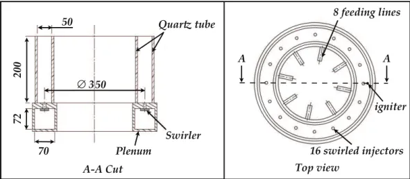
The MICCA experimental test rig installed at EM2C laboratory is composed of an annular plenum fed by 8 lines, a combustion chamber made of two cylindrical quartz tubes and 16 swirled injection systems (Fig.11.1). The injection system consists of 6 circular radial passages of 3 mm diameter connecting the plenum and an inner tube of 10 mm diameter, and 40 mm long ending in the combustion chamber. The transparent combustor walls allow a direct visualization of the flame front and the combustion chamber directly ends to the environment. The experimental geometry is shown in Fig.11.1 and more details on the technical set-up can be found in Bour-gouin et al.(2013). Ignition is triggered with a spark plug of 25 mJ deposit energy located on the bottom wall at a 191 mm radius near an injection system (see Fig.11.1). The flame motion during light-around is captured using a high speed camera at 6000 Hz, without filtering. How-ever, the cylindrical configuration does not allow precise experimental diagnostics to track the velocity field during the flame propagation. The arc length between two consecutive injectors is about 69 mm while the radial width of the combustor 50 mm. Comparing with the dimensions of the KIAI configuration, a rapid flame propagation along the bottom of the combustion chamber is expected. ! ! "#$%&'() !*!%+,-./(0,1 2)'3/(3 %45 ∅%6 %75 78 855 %45 9,:3;%-,<( =%>((?'0@%/'0(A BC%A)'3/(?%'0D(E-#3A '@0'-(3
Figure 11.1: Sketch of the MICCA experimental test rig. Dimensions are given in mm (extracted from
Bourgouin et al.(2013)).
The test rig is operated at atmospheric conditions. The plenum is fed with a perfectly pre-mixed propane-air mixture at an equivalence ratio of 0.76, with a total mass flow rate of 24.53 g/s
and a thermal power of 52 kW. The bulk velocity estimated in the swirler inner tubes is 17.1 m/s, corresponding to a Reynolds number of 11 000. The swirl number of the injection system has been estimated to 0.82 in a confined single injector configuration. Note that, experiments have shown a strong dependency of the overall ignition time to the thermal state of the test facility: ignition is longer when the combustion chamber is cold and shortens when the combustor is pre-heated (Bourgouin, 2014). The LES analysed hereafter are performed in preheated conditions, which differ from the experimental data presented inBourgouin et al.(2013).
11.2 Numerical set-up
11.2.1 Computational domain
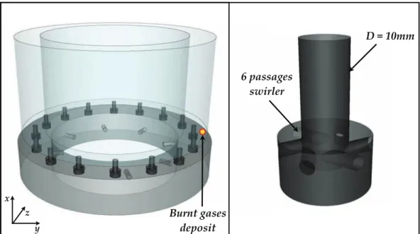
The complete geometry of Fig. 11.1 is used to study the ignition sequence with LES. A large volume is placed at the combustion chamber outlet to mimic the experimental configuration and minimize the influence of the outlet boundary condition on the ignition sequence. The whole computational domain as well as details of the swirler are presented in Fig. 11.2. The injector centers are located at the combustion chamber mean radius Rmean= 175mm.
!"#"$%&& '"()**)+,*" *-./0,/ 1 2 3 45/67"+)*,*" 8,(9*.7
Figure 11.2: Annular computational domain (left), details of the 6 passages swirler (right). The large
volume at the combustion chamber outlet is not shown here.
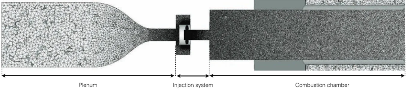
The overall LES grid size is about 310 millions of tetrahedral cells (Fig. 11.3), with a mesh characteristic size of 0.15 mm in the swirler passages and a linear increase from 0.15 mm to 0.5 mm in the inner tube of the injection system. In order to adequately capture the flame propagation in the whole chamber during light-around, the largest characteristic size of the grid is 1 mm at the combustion chamber exit which corresponds to 1.5 δ0
L, where δL0 is the laminar flame thickness at
Figure 11.3: Slices of the computational domain showing characteristic mesh size in the swirler passages
and in the combustion chamber.
Note that the geometry being periodic in the azimuthal direction, the non-reacting flow prior to ignition has been computed only in one eighth of the whole domain and duplicated eight times to generate the initial conditions for the full annular ignition simulation.
The analysis of the flow pattern has been performed on a single sector configuration since the cylindrical shape of the combustor prevents the use of PIV. The computational domain used to investigate the non-reacting flow is shown in Fig.11.4. A cylindrical plenum is placed upstream of the injection system and the combustion chamber is a 50 mm diameter cylinder with transparent walls to enable optical access. The grid characteristic size is similar to the one used in the annular configuration.
Plenum Injection system Combustion chamber
Figure 11.4: Computational domain and characteristic mesh size in a central cut-plane for the single
injector non-reacting flow study.
11.2.2 Numerical parameters
The numerical set-up is summarized in Table11.1. Ambient conditions are imposed numerically targeting a 101325 Pa outlet pressure and a 298 K inlet mixture temperature.
repro-Numerical parameter
Convection scheme TTGC: O(3) in space & time (Colin & Rudgyard,2000)
Diffusion scheme 2∆ operator
SGS model WALE (Nicoud & Ducros,1999)
Artif. viscosity Colin model: ǫ(2) = 0.05, ǫ(4)= 0.005
Boundary conditions
Mixture inlets NSCBC (Poinsot & Lele,1992) (mass flow rate)
Atmosphere inlet NSCBC (Poinsot & Lele,1992) (velocity)
Outlet NSCBC (3D) (Granet et al.,2010) (pressure)
Walls Adiabatic non-slipping walls
Table 11.1: Numerical parameters for LES of the MICCA configuration.
duce the laminar flame speed at φ = 0.76, Sl,0 = 0.239m/s, in analogy with the mechanism
proposed inFranzelli et al.(2010). The mechanism is described in Sec.4.4. The DTFLES model is used with the efficiency function fromCharlette et al.(2002) to model the flame/turbulence in-teractions. Considering the grid resolution compared to the laminar flame thickness ∆x/δL0 = 1.5,
the thickening factor F ranges from 5 to 8 from the bottom to the top of the combustion cham-ber. The simulation performed by the EM2C team in the SIMAC project framework used Tabu-lated Thermo-chemistry (TTC) model (Vicquelin et al.,2011) to describe the chemistry and the flame/turbulence interactions are modeled using the F-TACLES approach (Fiorina et al.,2010). In order to compare both combustion models, ignition is triggered with a 3 mm-wide burned gases spherical kernel centered at the same position as the experimental spark plug (see Fig.11.2). Indeed, the ED model used in the KIAI configurations is not compatible with the TTC/F-TACLES approach. Both the perfectly premixed conditions and the low level of turbulence in the energy deposit region guarantee the success of the early stages of ignition.
11.3 Non-reacting flow
The non-reacting flow generated by the swirler is first validated by comparison with experiments in a single injector configuration. These simulations have been performed by the EM2C team and are reported here to provide a complete description of the conditions prior to ignition. The full study evaluates the effect of mesh resolution, numerical scheme and subgrid scale modeling on the accuracy of the LES results. In the following, only the numerical set-up used for the full ignition sequence is compared to experimental results.
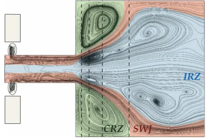
The non-reacting flow pattern is very similar to the KIAI configuration studied in Chap.6and the main flow structures are presented in Fig.11.5 with 2D projected streamlines: the IRZ and CRZ are separated by the SWJ and intense shear layers are located at the interface between the SWJ and the two recirculation zones. The IRZ spreads from the bottom of the injector tube to downstream in the combustion chamber.
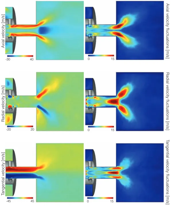
Figure11.6shows the mean and RMS components of the velocity field obtained from temporal averaging during 80 ms. The velocity is found to adopt constant profiles in the injector tube and
!"#
$"#
%&'
Figure 11.5: Time-averaged streamlines in the central cut plane of the single injector configuration.
The main flow regions are identified: Swirled Jet (SWJ), Inner Recirculation Zone (IRZ) and Corner Recirculation Zone (CRZ). Dashed vertical lines correspond to the velocity profile measure locations.
to rapidly expand at the combustion chamber dump plane. The strong rotation induced by the radial swirler is clearly demonstrated by the high magnitude of azimuthal velocity in the injector tube. A region of strong turbulent activity is located at the entrance plane in the combustion chamber: axial velocity fluctuations are strong in the outer shear layer denoting vortex shedding while both radial and azimuthal velocity fluctuations are strong both along the injector axis and in the chamber.
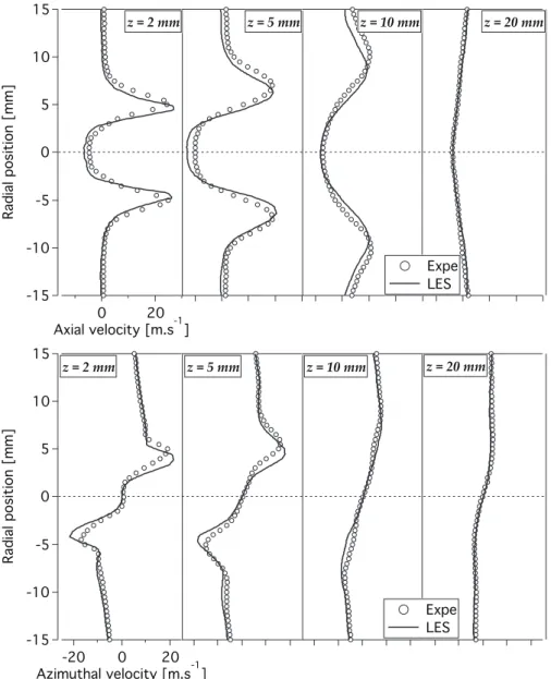
For a quantitative evaluation of the LES results, the mean axial and azimuthal velocity com-ponents are extracted at 4 axial positions (see Fig. 11.5) and compared with experiments in Fig.11.7. Both components are in fairly good agreement with experiments even though the SWJ opening is slightly underestimated in LES.
Axial velocity [m/s]
Radial velocity [m/s]
Tangential velocity [m/s]
Axial velocity fluctuations [m/s]
Radial velocity fluctuations [m/s]
Tangential velocity fluctuations [m/s]
-30 40 0 15
-20 20 0 15
-45 45 0 15
Figure 11.6: Mean and RMS velocity components in the central cut plane through the combustion
-15 -10 -5 0 5 10 15 Radial position [mm] 20 0 Axial velocity [m.s-1] !"#"$"%% !"#"&"%% !"#"'("%% !"#"$("%% Expe LES -15 -10 -5 0 5 10 15 Radial position [mm] -20 0 20 Azimuthal velocity [m.s-1] !"#"$"%% !"#"&"%% !"#"'("%% !"#"$("%% Expe LES
Figure 11.7: LES versus experiments: mean axial and azimuthal velocity components profiles at 4 axial
11.4 Ignition sequence
The experimental variability of the two first ignition phases is low since, similarly to the KIAI multi-injector burner, the energy deposit is performed in a region of low turbulence intensity. However, the duration of the light-around is found to vary: 6% variability is measured from 9 experimental trials. Furthermore, the early flame kernel phase is not computed in the LES. As a consequence, the comparison between LES and experiments during the burner to burner propagation starts after the kernel creation where time is set to 0. In Sec.11.4.1, the dynamics of the light around is qualitatively compared with experiments. In Sec.11.4.2 the LES results are analyzed in detail in order to track the flame pathways and identify the mechanisms responsible for the rapid propagation.
11.4.1 Light-around dynamics
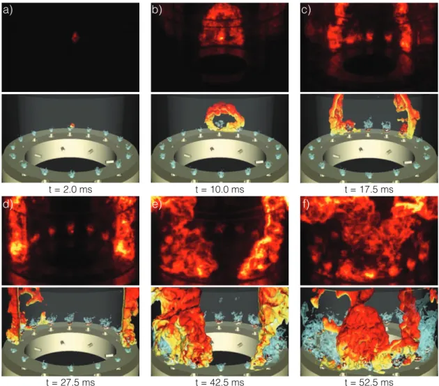
The flame position is compared at different instants between LES and experiments in Fig.11.8. In LES, the flame position is tracked by an iso-surface of temperature at T = 1781 K corresponding to 90 % of the adiabatic temperature while experimentally, the high speed camera enables direct visualization of the flame emissions. The different steps of the ignition sequence observed in the experiments are numerically recovered:
• (I) Initial kernel expansion: laminar kernel growth characterized by a slow increase in heat release rate, ending when the closest injector is ignited.
• (II) Arch-like flame propagation: the flame front meets the quartz windows and propagates towards the neighboring injectors with a half sphere shape. The arch breaks down as the upper front leaves the combustion chamber.
• (III) Two-front propagation: two flame fronts propagate through the combustor in opposite azimuthal directions and ignite the successive injectors as they pass by.
• (IV) Front merging: after the two fronts have spanned almost half of the combustion cham-ber they join and merge.
• (V) Steady state: burnt gases produced by the flame stabilized at the injector nozzle push the remaining flame front out of the combustor and a steady state is reached.
LES is able to reproduce with good accuracy the shape and the dynamics of the flame front. The simulations performed at EM2C using the TTC/F-TACLES model provide similar results (Philip et al.,2014a).
11.4.2 Overall burning rate
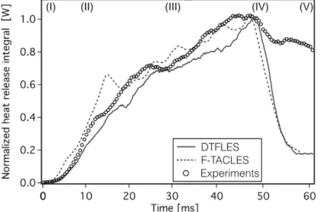
The temporal evolution of the integral of heat release in the combustion chamber (RV ˙ωT dV)
t = 2.0 ms t = 10.0 ms t = 17.5 ms t = 52.5 ms t = 42.5 ms t = 27.5 ms a) b) c) d) e) f)
Figure 11.8: Snapshots of the ignition sequence: experimental direct imaging of the flame emission
colored for visualization purposes (top rows) versus iso-surfaces of T = 1781 K colored by the axial velocity and U = 25 m.s−1
in light blue extracted from the LES (bottom rows).
integral extracted from the high speed camera recordings. The results obtained with the TTC/F-TACLES model (Vicquelin et al., 2011; Fiorina et al.,2010) presented by Philip et al.(2014a) are also reported. A very good agreement is obtained between models and experiments. All three integrals are normalized by their maximum values. Comparing the results obtained with the DTFLES and the F-TACLES models demonstrates the robustness of the LES approach and its limited sensitivity to the combustion model, at least when investigating the light-around in gaseous flows. The heat release follows a smooth increase during the kernel phase and is followed by a sharp increase during the arch phase. Then during the two-front flame propagation, the heat release continues to increase with a lower slope. The overall heat release is maximum when the flame fronts merge and this maximum is followed by a steep decrease of the heat release as the flame front elements are pushed out of the combustion chamber. Finally, the combustor reaches a stable regime. LES results are found to follow the experiments up to 50 ms where differences appears since the camera captures flame elements outside the combustion chamber (see t = 52.5
of Fig.11.8). 60 50 40 30 Time [ms] 350 300 250 200 150 100 50 0 30 20 10 0 Time [ms] 40 30 20 Time [ms] 1.0 0.8 0.6 0.4 0.2 0.0 N ormalized heat release integral [W] 0
(I) (II) (III) (IV) (V)
Experiments F-TACLES DTFLES
Figure 11.9: Temporal evolution of the integrated heat realease in the combustion chamber. Comparison
between experiments, and the two LES using DTLES and TTC/F-TACLES.
To further evaluate the burning rate during the ignition sequence, the mean consumption speed Sc is calculated as:
Sc=
R
V ˙ωT dV
ρfYF,fAf lQr (11.1)
where Af l is the total flame surface computed from the FSD (see Eq. (7.9)) and Qr is the heat
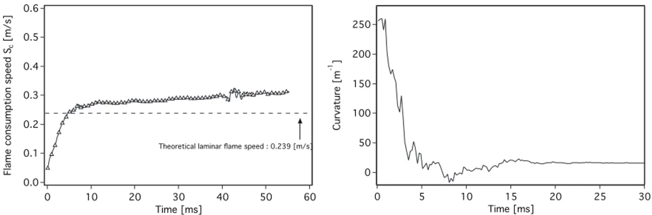
of combustion of propane. The temporal evolution of Sc is plotted in Fig.11.10(left) along with
the value of S0
L. Sc is first below SL0 mainly due to the effect of stretch induced by the mean
positive curvature K of the flame kernel as shown in Fig.11.10(right). The curvature is computed as K = ∇.n with n the flame surface normal. As the flame front expands, Sc increases to a value
about 15% higher than S0
Land remains at this rate during the whole ignition sequence. Past the
arch-like stage, the mean curvature along the flame front reaches a stable low value of about 10 m−1. Note that, the absolute value of S
c strongly depends on the evaluation of the flame surface
Af l. Defining the flame front surface for a turbulent premixed flame is not an easy task since the
flame front has a finite thickness and Af l depends on the c-isolevel chosen. Using Eq. (7.9) in the
present analysis could result in an underestimation of the flame surface that can directly increase Sc as observed in Fig.11.10(right).
11.4.3 Flame path
To track the flame front position, a cylindrical reference frame (R,θ,zcyl) is introduced: the axial
direction zcyl aligned with the x-axis of the cartesian reference frame corresponding to the
sym-metry axis of the azimuthal configuration. The angular position θ is zero along the y-axis where ignition is triggered. To better characterize the flame front displacement, two leading points of the flame front are tracked: they are defined as the location on the T = 1781 K iso-surface having the maximum absolute value of θ, θ being positive in the upper part of the combustion chamber and negative in the lower part (see Fig.11.11). The positions of the leading points are plotted in a R-θ map along with the time at which the flame front reaches the different injectors
0.6 0.5 0.4 0.3 0.2 0.1 0.0 Flame con sumption speed Sc [m/s] 60 50 40 30 20 10 0 Time [ms]
Theoretical laminar flame speed : 0.239 [m/s]
250 200 150 100 50 0 Curvature [ m -1 ] 30 25 20 15 10 5 0 Time [ms]
Figure 11.10: Temporal evolution of mean consumption speed Sc(left) and mean flame curvature (right).
in Fig.11.11. Point to point large variations of the leading point position corresponds to a switch between two flame elements. Arrows indicate the motion induced by the injector swirl: in the positive θ direction in the inner part and negative θ direction in the outer part.
Ignition starts at Rspark = 191mm > Rmean. The upper front leading point rapidly shifts to
a Rlp,up < Rmean (where the lp subscript refers to leading point) location as the inner path is
shorter than the outer one and the swirl induced motion is favorable to flame displacement. On the contrary for the lower front, the swirl motion has an adverse effect on the flame propagation direction and the leading point radius Rlp,low is alternatively lower and higher than Rmean. This
behavior is coherent with the observations ofBourgouin et al.(2013), though a precise flame path has not been observed experimentally.
The times reported in Fig. 11.11 indicate that the upper flame front is delayed as compared to the lower one at first, but finally reaches the opposite injector (located at θ = π) sooner than the lower front. Since ignition is triggered at Rspark = 191mm > Rmean, the flame kernel first
undergoes a bulk displacement towards negative θ due to the outer negative rotation before being able to propagate in the opposite direction. As observed in the KIAI multi-burner experiment, during the early stage of kernel development, the large scale structures of the non-reacting flow are driving the motion of the flame front. The temporal evolution of the leading point angle is reported in Fig.11.12, and the initial delay of the upper flame front is shown to be compensated by a higher flame velocity at later times. Due to the advance of the upper front, merging of the two flame fronts is not located at the position opposite to the spark deposit: the merging is switched towards the lower part of the combustion chamber. Once again, this is coherent with the observations ofBourgouin et al.(2013).
Finally the axial position of the leading points is reported in Fig. 11.13 as function of the leading point angle while the dashed vertical lines indicate the positions of the swirler inlet. During the kernel and arch phases, the axial position of the leading point gradually increases. As the upper flame front reaches the combustor exit, the two flame fronts flatten and the leading point positions switch towards an upstream locations. During the propagation phase, the leading point of the upper flame front is located approximatively around zcyl,lp,up = 35mm while the
lower portion is zcyl,lp,low= 20mm. This difference can be related to the position of the maximum
-0.2 -0.1 0.0 0.1 0.2 -0.2 -0.1 0.0 0.1 0.2 !" #$% &''($ $)*+*#)' ,-*($ $)*+*#)' *./.010.23 *%)"../.4516.23 *%)"../.5715.23 *%)"./.8719.23 *%)"./.7:15.23 *-;./.4715.23 *-;./.5915.23 *-;./.851<.23 *-;./.771<.23 = > ? @ Lower half Upper half
θ
Figure 11.11: Evolution of the upper (white) and lower (grey) leading points in a R-θ map. Time at
which the flame reaches injectors located at θ = π/4 [π/4] is indicated.
the swirl motion so that the leading point follows the path exhibiting high velocity. The opposite applies for the lower flame front, where the leading point follows low velocity locations due to the adverse effect of swirl on the propagation. This low velocity region corresponds to the CRZ.
11.4.4 Effect of burnt gas expansion
The magnitude of the mean flame consumption speed reported in Fig.11.10is several times lower than the flame propagation speed estimated from the overall ignition delay (πRmean/τign ≃ 11
m/s) indicating that the flame propagation is not directly responsible from the rapid ignition. Similarly to the study of Boileau et al. (2008) or the one for the KIAI burner presented in Chap.10, the burnt gas expansion is the mechanism driving the propagation. The density drop across the turbulent flame brush results in an acceleration of the fresh gases in front of the flame front. To better understand the flame pathways described in Sec.11.4.3, it is interesting to eval-uate the axial distribution of azimuthal velocity Vθ. The axial distribution of Vθ is evaluated in
180 160 140 120 100 80 60 40 20 0 L eadin g poin t an gle [°] 50 40 30 20 10 0 Time [ms] Lower half Upper half
Figure 11.12: Temporal evolution of the position angle of the upper (white) and lower (grey) leading
points. 100 80 60 40 20 0 Axial position [mm] 180.0 157.5 135.0 112.5 90.0 67.5 45.0 22.5 0.0
Leading point angle [°] Lower half Upper half
Figure 11.13: Evolution of the upper (white) and lower (grey) leading points axial position as function
of the leading point angle. Dashed vertical lines indicate the position of the injectors.
a slice θ = −79◦ slice and plotted at 5 instants in Fig.11.14. The acceleration of the fresh gases
is not uniform in the zcyl-direction with maximum values in the lower part of the combustion
chamber where the swirl motion adds to the value of Vθ. This explains that the leading point
remains in the lower part of the combustion chamber as well as the oblique front observed in LES and experiments during the two-front propagation stage.
To evaluate the spatial distribution of the fresh gas velocity, the azimuthal distribution of the azimuthal velocity Vθ is averaged in a slab of 5 mm through the combustion chamber located at
x = 30mm. The results are plotted in Fig.11.15for 5 instants during the ignition sequence. The initial distribution is only modulated by the swirl motion induced by the injectors. After 10 ms, Vθ shows a maximum value about 9 m/s near the preheat zone of the flame. The velocity then
decreases with increasing distance from the flame. Up to 35 ms, this maximum value of Vθ is
observed in the preheat zone but as the opposite flame fronts get closer, the azimuthal maximum value is reduced. The upper and lower flame fronts induce a similar acceleration of the fresh gases but in opposite directions. As they get closer, the fresh gases are unable to accelerate and a backflow is observed (t = 40 ms in Fig.11.15) with a positive azimuthal velocity in the whole
0.20 0.15 0.10 0.05 0.00 Axial distance [m] -8 -6 -4 -2 0 Azimuthal velocity [m/s] t = 5.0 ms t = 10.0 ms t = 13.0 ms t = 16.0 ms t = 19.0 ms
Figure 11.14: Axial distribution of mean Vθcomputed in a slice θ = −79◦at 5 instants.
10 8 6 4 2 0 -2 Azimuth al velocity [m/s] -180.0 -157.5 -135.0 -112.5 -90.0 -67.5 -45.0 -22.5 0.0 2000 1600 1200 800 400 Temperatu re [K] t = 0.0 ms 10 8 6 4 2 0 Azimuthal velocity [m/s] -180.0 -157.5 -135.0 -112.5 -90.0 -67.5 -45.0 -22.5 0.0 2000 1600 1200 800 400 Temperature [K] t = 10.0 ms 10 8 6 4 2 0 Azimuthal velocity [m/s] -180.0 -157.5 -135.0 -112.5 -90.0 -67.5 -45.0 -22.5 0.0 2000 1600 1200 800 400 Temperature [K] t = 20.0 ms 10 8 6 4 2 0 Azimuthal velocity [m/s] -180.0 -157.5 -135.0 -112.5 -90.0 -67.5 -45.0 -22.5 0.0 2000 1600 1200 800 400 Temperature [K] t = 30.0 ms 10 8 6 4 2 0 Azimuthal velocity [m/s] -180.0 -157.5 -135.0 -112.5 -90.0 -67.5 -45.0 -22.5 0.0 Azimuth [°] 2000 1600 1200 800 400 Temperatu re [K] t = 40.0 ms
Figure 11.15: Azimuthal distribution of mean azimuthal velocity Vθ(full line) and temperature (dashed
11.4.5 Conclusion
The ignition dynamics of an azimuthal configuration has been studied using LES and compared to experiments when available. From the comparison of direct visualization of the flame front, LES is found to reproduce well the flame front shape and motion. A quantitative comparison based on integral values of the light signal on the experiments side and heat release rate on the numerical side confirm that LES is able the reproduce the light-around dynamics. The comparison of the results obtained with another combustion model (TTC-F-TACLES) indicates that the LES results are not highly sensitive to the numerical parameters, at least in this configuration.
The large set of numerical data has then been analyzed to investigate the flame pathway and highlight the effect of the burnt gas expansion on the flame front dynamics. The flame is found to propagate in the lower part of the combustor in accordance with experiments, and its leading point motion is not altered by the flow issued from the swirler. Similarly to a spherically expanding flame, the flame front is found to induce an outward motion of the fresh gases during stage (II). The maximum azimuthal velocity is then found in the flame front and is observed during the whole stage (III) even though burnt gases exit the combustion chamber. At the beginning of stage (IV), the effect of burnt gases expansion is reduced since the two flame front evolve in opposite direction so that the flame front velocity is reduced. The overall ignition delay is driven by the density ratio between fresh and burnt gases, which is coherent with the little sensitivity of the LES results to the combustion model. As compared to the KIAI multi-burner experiment studied in Chap.10, several observation are formulated:
• the flame propagates in the lower part of the combustion chamber, which is coherent with the spanwise propagation mode described in the KIAI multi-burner configuration.
• the light-around phase duration is longer and numerous injectors are ignited, which allows to investigate the driving mechanisms.
• the annular configuration remove the azimuthal confinement so that the thrust effect due to burnt gas expansion is more pronounced compared to the KIAI multi-burner case. The fresh gases acceleration is observed through the whole combustion chamber.
• the effect the individual injector flow pattern on the ignition dynamic is lower than in the KIAI multi-burner.
This study of the light-around process in an annular configuration is a step towards a better understanding of the ignition process in realistic configurations, and it complement the study on the effect of inter-injector spacing performed in the KIAI multi-burner setup. Nonetheless, both experimental setups are still far from the complexity of realistic gas turbines combustion chambers and several complexity of real combustors are not taken into account: high Reynolds number flow, multi-phase flow or axial confinement of the combustion chamber.
Conclusions and Perspectives
The work presented in this Ph.D thesis deals with the ignition process of aeronautical gas tur-bines, from the initial flame kernel generation to the complete light-up of the combustion cham-ber. Such transient processes are complex and because of the technological complexity of aero-engines, numerical simulations are currently the most promising methods capable of shedding some light on the mechanisms controlling the ignition performances. The present work relies on experimental data to validate LES results, as a starting point of a more detailed study of the driving mechanisms. Two main aspects of the ignition process are studied:
• The kernel initiation and growth in highly swirled partially premixed conditions is studied in Chap.7. Compared to previous LES study (Lacaze et al.,2009a;Jones & Tyliszczack, 2010; Subramanian et al.,2010), the single injector KIAI configuration is more represen-tative of realistic gas turbine applications since it features a swirling flow with higher tur-bulence levels, recirculation zones and partial premixing effects. Multiple LES of ignition sequences are performed to provide an extensive database of ignition events and construct an ignition probability from brute force LES computations. The study indicates that LES is able to reproduce the experimental ignition probability, proving that LES captures the main mechanisms affecting the ignition process, with the good variability. The LES database is analyzed and confirms the existence of two ignition failure modes observed in simpler configurations (Smith et al.,1986;Ahmed et al.,2007a;Mastorakos,2009): failure of flame kernel initiation and kernel quenching at later times. LES results reveal that the late failure is the result of two main quenching mechanisms: inflammable mixture pockets and kernel dislocations due to large scale deformations and flame/flame interactions. In agreement with experimental studies (Cardin,2013), the first failure mode is found to be controlled by the amount of fuel readily available in the deposit location surroundings. The second mode is more challenging to predict as it results of the combination of several mechanisms occurring at different times and locations along the kernel trajectory. The results of the LES study are then used to develop a model to predict the ignition probability in Chap.8. The aim is to include transport of the flame kernel in the prediction of its survival probabil-ity. A methodology combining a statistic of the kernel trajectories and of the non-reacting flow characteristics is proposed and applied to the KIAI single burner with success in the premixed case, but with limited performance on the non-premixed case.
• The light-round process is then studied in two experiential test rigs. In the KIAI multi-burner study (Chap. 10), quantitative comparisons with experiments proves that LES is able to recover the effect that the inter-injector distance has on the ignition dynamics. The joint analysis of the experimental and numerical results highlights the existence of two propagation modes: rapid and safe spanwise propagation for low spacings, and longer and uncertain axial propagation for high spacings. The effect of the non-reacting flow pattern and the burnt gas expansion effect on the occurrence of one or the other of the propa-gation modes is also presented. The ignition sequence in the annular MICCA experiments (Chap.11) enables to investigate a more realistic configuration, where the light-round phase is more representative of engine configuration. Compared to the KIAI multi-burner con-figuration, removing the azimuthal confinement allows to evaluate the full extend of the burnt gas expansion effect on the flame front propagation speed. Comparison of the LES results obtained with two combustion models shows that the light-round phase is not highly sensitive to the numerical setup since the flame propagation is driven by the burnt gas ex-pansion, i.e. by the adiabatic flame temperature and the consumption speed, which are well reproduced by most of the combustion models.
In addition to the work presented in this thesis, a study of a realistic combustor relight at high altitude conditions has been performed in the framework of the LEMCOTEC project (see Figs. 12.1 & 12.2). Compared to the several experimental configurations investigated in this work, the increased complexity of the industrial application emphasizes the key features that are still missing to validate the LES tool in realistic configuration:
• the key ingredient missing from all of the experiments presented here is the effect of the two-phase flow on the ignition dynamics. The study of the industrial application clearly highlights the first degree effect of the liquid fuel distribution upon the ignition dynamics, especially at relight conditions.
• although the KIAI experiments is clearly a first step towards realistic flow conditions, the flow in a real combustor is more turbulent and complex, with secondary air flow added to the flame/kernel interactions.
To address these issues, the different laboratories already involved in the work presented here (EM2C, CORIA and CERFACS) are part of the TIMBER project, in a collaborative effort to investigate the effects of the liquid phase on the ignition process. One of the objectives is to construct an experimental database of ignition in two-phase flow in order to validate the LES tool. Both the KIAI single burner (Chap.7) and multi-burner (Chap.10) as well as the MICCA annular test bench (Chap.11) will be equipped of liquid injection(s) to study both Phase 2 and
t = 25.0 ms
t = 20.0 ms
t = 43.0 ms
t = 30.0 ms
Abdel-Gayed, R., Al-Khishali, K. & Bradley, D. 1984 Turbulent burning velocities and flame straining in explosions. Proc. R. Soc. Lond. A 391, 393–414. (9,35, and66)
Abdel-Gayed, R. & Bradley, D.1985 Criteria for turbulent propagation limits of premixed flames. Combustion and Flame 62, 61–68. (73,152, and153)
Abdel-Gayed, R. & Bradley, D. 1989 Combustion regimes and the straining of turbulent premixed flames. Combustion and Flame 76, 213–218. (134)
Abdel-Gayed, R., Bradley, D. & Lawes, M.1987 Turbulent burning velocities: a general correlation in terms of straining rates. Proc. R. Soc. Lond. A 414, 389–413. (66,134, and155) Abdel-Gayed, RG, Bradley, D, Lawes, M & Lung, FK-K1988 Premixed turbulent burn-ing durburn-ing explosions. Proceedburn-ings of the Combustion Institute 21 (1), 497–504. (9,66, and67) Advisory Council for Aeronautics Research in Europe2010 Aeronautics and air
trans-port: Beyond vision 2020 (towards 2050). Tech. Rep.. ACARE. (1)
Aggarwal, S. K. 1998 A review of spray ignition phenomena: present status and future re-search. Progress in Energy and Combustion Science 24, 565–600. (60)
Aggarwal, S. K. & Sirignano, W. A.1984 Ignition of fuel sprays: deterministic calculations for idealized droplet arrays. Proceedings of the Combustion Institute 20, 1773–1780. (61) Ahmed, S.F., Balachandran, R., Marchione, T. & Mastorakos, E.2007a Spark ignition
of turbulent non premixed bluff-body flames. Combustion and Flame 151, 366–385. (9,63,
64,72,73,74,75,135,147,186, and213)
Ahmed, S.F., Balachandran, R. & Mastorakos, E.2007b Measurments of ignition prob-ability in turbulent non-premixed counterflow flames. Proc. of the Combustion Institute 31, 1507–1513. (9,135)
Ahmed, S. F. & Mastorakos, E.2006 Spark ignition of lifted turbulent jet flames. Combus-tion and Flame 146 (1-2), 215–231. (9,63,72,116,134,135, and186)
Akindele, O., Bradley, D., Mak, P. & McMahon, M. 1982 Spark ignition of turbulent gases. Combustion and Flame 47, 129–155. (9,60,61,67, and155)
Allouis, C., Beretta, F. & Amoresano, A.2008 Experimental study of lean premixed pre-vaporized combustion fluctuations in gas turbine burner. Combustion Science and Technology
180 (5), 900–909. (2)
Angelberger, C., Veynante, D., Egolfopoulos, F. & Poinsot, T. 1998 Large eddy simulations of combustion instabilities in premixed flames. pp. 61–82. Center for Turbulence Research, NASA Ames/Stanford Univ. (47,48)
AVBP 2011 AVBP Handbook - http://cerfacs.fr/∼ avbp/AVBP V6.X/HANDBOOK. CER-FACS. (44)
Bach, E., Kariuki, J., Dawson, J. R. & Mastorakos, E. 2013 Spark ignition of single bluff-body premixed flames and annular combustors. (10,164, and165)
Ballal, D. R. & Lefebvre, A. H.1975 The influence of flow parameters on minimum ignition energy and quenching distance. Proc. Combust. Inst. 15, 1473–1481. (9,60)
Ballal, D. R. & Lefebvre, A. H. 1977 Ignition and flame quenching in flowing gaseous mixtures. Proceedings of the Royal Society of London. Series A 357, 163–181. (9,60, and61) Ballal, D. R. & Lefebvre, A. H.1978 Ignition and flame quenching of quiescent fuel mists.
Proceedings of the Royal Society of London. Series A 364, 277–294. (60,61)
Ballal, D. R. & Lefebvre, A. H.1979 Ignition and flame quenching of flowing heterogeneous fuel-air mixtures. Combustion and Flame 35, 155–168. (61)
der Bank, R. Von, Donnerhack, S., Rae, A., Cazalens, M., Lundblach, A. & Dietz, M.2014 Lemcotec: improving the core-engine thermal efficiency. (3)
Barbosa, S., Scouflaire, P. & Ducruix, S.2009 Time resolved flowfield, flame structure and acoustic characterization of a staged multi-injection burner. Proc. of the Combustion Institute . (2)
Barr´e, D. 2014 Numerical simulation of ignition in aeronautical combustion chambers. PhD thesis, INP Toulouse. (10,11,74,78,95,101,102, and168)
Barr´e, D., Kraushaar, M., Staffelbach, G., Moureau, V. & Gicquel, L.Y.M. 2013 Compressible and low Mach number LES of a swirl experimental burner. Comptes rendus de l’Acad´emie des sciences M´ecanique 341, 277–287. (89,91)
Bauerheim, M. 2014 Theoretical and numerical study of symmetry breaking effects on az-imuthal thermoacoustic modes in annular combustors. PhD thesis, INP Toulouse. (164) Baum, M. & Poinsot, T.1995 Effects of mean flow on premixed flame ignition. Combustion
Science and Technology 106 (1-3), 19. (60,65)
Beduneau, J-L. & Kim, B.2003 Measurements of minimum ignition energy in premixed lami-nar methane/air flow by using laser induced spark. Combustion and Flame 132, 653–665. (9,
60)
Beer, J. M. & Chigier, N. A.1983 Combustion aerodynamics. Malabar, Florida: Krieger. (3,
82)
Berman, V., Riazantsev, I. & Shevtsova, V. 1981 Asymptotic analysis of the process of igniting a combustible gas mixture by thermal inhomogeneity. PMM U.R.S.S. . (58)
Bilger, R.W.1989 The structure of turbulent nonpremixed flames. Proceedings of the Com-bustion Institute 22 (1), 475–488. (29,30)
Bilger, R. W., Antonia, R. & Sreenivasan, K.1976 Determination of intermittency from the probability density function of a passive scalar. Physics of Fluids 19 (10), 1471–1474. (132)
Billant, P., Chomaz, J-M. & Huerre, P.1998 Experimental study of vortex breakdown in swirling jets. Journal of Fluid Mechanics 376, 183–219. (82,83)
Birch, A. D., Brown, D.R., Dodson, M. G. & Thomas, J. R. 1977 The turbulent con-centration field of a methnae jet. Journal of Fluid Mechanics 88 (3), 431–449. (132, 147, and148)
Birch, A. D., Brown, D. R. & Dodson, M.1981 Ignition probabilities in turbulent mixing flows. Proc. Combust. Inst. 18, 1775–1779. (62,63,72,116,132, and147)
Boileau, M. 2007 Simulation aux grandes ´echelles de l’allumage diphasique des foyers a´eronautiques. Phd thesis, INP Toulouse. (11,75, and163)
Boileau, M., Staffelbach, G., Cuenot, B., Poinsot, T. & B´erat, C.2008 LES of an ignition sequence in a gas turbine engine. Combustion and Flame 154 (1-2), 2–22. (10,11,
163,164, and207)
Borghi, R.1985 On the structure and morphology of turbulent premixed flames. In Rec. Adv. in Aerospace Sci.(ed. C. Bruno & C. Caseci), pp. 117–138. (68)
Boudier, P., Henriot, S., Poinsot, T. & Baritaud, T.1992 A model for turbulent flame ignition and propagation in spark ignition engines. Proceedings of the Combustion Institute
24, 503–510. (9,65, and155)
Bourgouin, J-F.2014 Experimental study of azimuthal instabilities in an annular combustion chamber. PhD thesis, Ecole Centrale Paris. (197)
Bourgouin, J-F., Durox, D., Schuller, T., Beaunier, J. & Candel, S. 2013 Ignition dynamics of an annular combustor equipped with multiple swirling injectors. Combustion and Flame 160 (8), 1398–1413. (10,12,164,165,166,188,195,196,197, and206)
Boussinesq, J.1877 Th´eorie de l’´ecoulement tourbillant. M´em. Pr´esent´es par Divers Savants. Acad. Sci. Inst. Fr. 23, 46–50. (44)
Bradley, D., Gaskell, P. & Gu, X. 1996 Burning velocities, markstein lengths and flame quenching for spherical methane-air flames: a computational study. Combustion and Flame
104, 176–198. (9)
Bradley, D., Lawes, M. & Mansour, M.2011 Correlation of turbulent burning velocities of ethanol-air measured in a fan-stirred bomb up to 1.2 MPa. Combustion and Flame 158, 123–138. (66)
Bradley, D., Sheppard, C., Suardjaja, I. & Woolley, R. 2004 Fundamentals of high-energy spark ignition with lasers. Combustion and Flame 138, 55–77. (6,9,66, and67)
Bray, K.N.C. & Cant, R.S.1991 Some applications of kolmogorov’s turbulence research in the field of combustion. Proceedings of the Royal Society of London. Series A: Mathematical and Physical Sciences 434 (1890), 217–240. (34)
Bray, K. N. C. & Moss, J. B. 1977 A closure model for the turbulent premixed flame with sequential chemistry. Combustion and Flame 30, 125–131. (45)
Buckmaster, J.D. 2002 Edge-flames. Progress in Energy and Combustion Science 28 (5), 435–475. (70)
Bush, W. & Fendell, F.1970 Asymptotic analysis of laminar flame propagation for general lewis numbers. Combustion Science and Technology 1 (6), 421–428. (27)
Butler, T. D. & O’Rourke, P. J. 1977 A numerical method for two-dimensional unsteady reacting flows. Proceedings of the Combustion Institute 16 (1), 1503 – 1515. (46)
CAEP 2010 CAEP/8 NOx stringency cost-benefit analysis demonstration using AMPT-IMPACTS. Tech. Rep.. International Civial Aviation Organization. (2)
Candel, S. & Poinsot, T. J.1990 Flame stretch and the balance equation for the flame area. Combustion Science and Technology 70, 1–15. (27)
Cardin, C. 2013 Etude exp´erimentale des ph´enom´enes physico-chimiques de l’allumage dans des ´ecoulements laminaires et turbulents. PhD thesis, INSA Rouen. (9,62,63,67,125,129, and213)
Cardin, C., Renou, B., Cabot, G. & Boukhalfa, A.M.2013 Experimental analysis of laser-induced spark ignition of lean turbulent premixed flames: New insight into ignition transition. Combustion and Flame 160 (8), 1414–1427. (62)
Chakraborty, N. & Cant, R.S.2004 Unsteady effects of strain rate and curvature on turbu-lent premixed flames in an inflow-outflow configuration. Combustion and Flame 137, 129–147. (115)
Chakraborty, N. & Mastorakos, E.2006 Numerical investigation of edge flame propagation characteristics in turbulent mixing layers. Physics of Fluids 18. (9)
Chakraborty, N. & Mastorakos, E.2008 Direct Numerical Simulations of localised forced ignition in turbulent mixing layers: the effects of mixture fraction and its gradient. Flow, Turbulence and Combustion 80, 155–186. (30,68)
Chakraborty, N., Mastorakos, E. & Cant, R. S. 2007 Effects of turbulence on spark ignition in inhomogeneous mixtures: a direct numerical simulation study. Combustion Science and Technology 179, 293–317. (65,68,69, and192)
Champion, M., Deshaies, B., Joulin, G. & Kinoshita, K.1986 Spherical flame initiation: Theory versus experiments for lean propane-air mixtures. Combustion and Flame 65 (3), 319–337. (9,59)
Charlette, F., Veynante, D. & Meneveau, C.2002 A power-law wrinkling model for LES of premixed turbulent combustion: Part I - non-dynamic formulation and initial tests. Com-bustion and Flame 131, 159–180. (48,101,199, and246)
Chen, J. H., Choudhary, A., De Supinski, B., DeVries, M., Hawkes, E.R., Klasky, S., Liao, W.K., Ma, K.L., Mellor-Crummey, J., Podhorszki, N. et al.2009 Terascale Direct Numerical Simulations of turbulent combustion using S3D. Computational Science & Discovery 2 (1), 015001. (40)
Chen, J. H. & Im, H. G.1998 Correlation of flame speed with stretch in turbulent premixed methane/air flames. Proceedings of the Combustion Institute 27 (1), 819–826. (71,119,122, and239)
Cheng, L., Dianat, M., Spencer, A. & McGuirk, J. J.2012 Validation of LES predictions of scalar mixing in high-swirl fuel injector flows. Flow, Turbulence and Combustion 88 (1-2), 143–168. (93)
Clavin, P. 1985 Dynamic behavior of premixed flame fronts in laminar and turbulent flows. Progress in Energy and Combustion Science 11, 1–59. (27)
Colin, O., Ducros, F., Veynante, D. & Poinsot, T. 2000 A thickened flame model for Large Eddy Simulations of turbulent premixed combustion. Physics of Fluids 12 (7), 1843– 1863. (45,47,170, and191)
Colin, O. & Rudgyard, M.2000 Development of high-order Taylor-Galerkin schemes for LES. Journal of Computational Physics 162, 338–371. (53,81,99,101,170,199,241,244, and247) Cook, A. W. & Riley, J. J.1994 A subgrid model for equilibrium chemistry in turbulent flows.
Physics of Fluids 6 (8), 2868 – 2870. (46)
Cook, A. W. & Riley, J. J.1998 Subgrid scale modeling for turbulent reacting flows. Com-bustion and Flame 112, 593 – 606. (46)
Cordier, M.2013 Allumage et propagation de flamme dans les ´ecoulements fortement swirl´es : ´etudes exp´erimentales et num´eriques. PhD thesis, INSA Rouen. (10,12,73,77,79,92,93,95,
96,97,103,104,109,116,125,129,138,153,155,156,157,158,163,166,168,172, and173) Cordier, M., Vandel, A., Cabot, G., Renou, B. & Boukhalfa, A.2013a Laser-induced
spark ignition of premixed confined swirled flames. Combustion Science and Technology
185 (3), 379–407. (73,74,83, and163)
Cordier, M., Vandel, A., Renou, B., Cabot, G., Boukhalfa, M. & Cazalens, M.2013b Spark ignition of confined swirled flames: experimental and numerical investigation. ASME . (73,136)
Cordier, M., Vandel, A., Renou, B., Cabot, G., Boukhalfa, M.A., Esclapez, L., Barr´e, D., Riber, E., Cuenot, B. & Gicquel, L.Y.M.2013c Experimental and numerical analysis of an ignition sequence in a multiple-injectors burner. American Society of Mechanical Engineers. (168)
Cuenot, B. & Poinsot, T.1994 Effects of curvature and unsteadiness in diffusion flames. im-plications for turbulent diffusion combustion. Proceedings of the Combustion Institute 25 (1), 1383–1390. (36,37)
Dahms, R., Drake, M., Fansler, T., Kuo, T.-W. & Peters, N. 2011 Undestanding ig-nition processes in spray-guided gasoline engines using high-speed imaging and the extended spark-ignition model sparkcimm. part a: Spark channel processes and the turbulent flame front propagation. Combustion and Flame 158, 2229–2244. (9)
Dale, J., Checkel, M. & Smy, P.1997 Application of high energy ignition systems to engines. Progress in Energy and Combustion Science 23, 379–398. (9)
Deshaies, B. & Joulin, G. 1984 On the initiation of a spherical flame kernel. Combustion Science and Technology 37 (3-4), 99–116. (9,58, and59)
Doerr, T.2012 Introduction to aero-engine gas turbine combustion. In Lecture Series 2012-04 (ed. Von Karman Institute for Fluid Dynamics). Von Karman Institute for Fluid Dynamics. (4)
Dold, J. W. 1989 Flame propagation in a nonuniform mixture: analysis of a slowly varying triple flame. Combustion and Flame 76, 71–88. (30)
Domingo, P. & Vervisch, L.1996 Triple flames and partially premixed combustion in autoigni-tion of non-premixed turbulent mixtures. Proceedings of the Combusautoigni-tion Institute 26 (1), 233–240. (30)
Donea, J. & Huerta, A.2003 Finite element methods for flow problems. John Wiley & Sons. (53)
Dopazo, C.1994 Recent developments in PDF methods. In Turbulent Reacting Flows (ed. P. A. Libby & F. A. Williams), pp. 375 – 474. London: Academic. (45)
Driscoll, J. F. 2008 Turbulent premixed combustion: Flamelet structure and its effect on turbulent burning velocities. Progress in Energy and Combustion Science 34, 91–134. (34,
35)
Duclos, J-M. & Colin, O.2001 Arc and kernel tracking ignition model for 3D Spark-ignition engine calculations. COMODIA 2001 5, 343–350. (65,134)
Echekki, T. & Chen, J. H.1996 Unsteady strain rate and curvature effects in turbulent pre-mixed methane-air flames. Combustion and Flame 106, 184–202. (71)
Echekki, T. & Chen, J. H. 1998 Structure and propagation of methanol–air triple flames. Combustion and Flame 114 (1), 231–245. (31)
Echekki, T. & Chen, J. H.1999 Analysis of the contribution of curvature to premixed flame propagation. Combustion and Flame 118, 308–311. (26,239)
Echekki, T. & Kolera-Gokula, H.2007 A regime diagram for premixed flame kernel-vortex interactions. Physics of Fluids 19. (68)
Eckhoff, R. K., Ngo, M. & Olsen, W. 2010 On the minimum ignition energy (MIE) for propane/air. Journal of Hazardous Materials 175, 293–297. (9)
Eichenberger, D. & Roberts, W. 1999 Effect of unsteady stretch on spark-ignited flame kernel survival. Combustion and Flame 118, 469–478. (9,68)
Esclapez, L., Riber, E. & Cuenot, B. 2015 Ignition probability of a partially premixed burner using les. Proceedings of the Combustion Institute 65 (3), 3133–3141. (96)
Eyssartier, A.2012 LES of two-phase reacting flows: stationary and transient operating con-ditions. PhD thesis, INP Toulouse. (11)
Eyssartier, A., Cuenot, B., Gicquel, L. & Poinsot, T.2013 Using LES to predict ignition sequences and ignition probability of turbulent two-phase flames. Combustion and Flame 160, 1191–1207. (10,74,133,137,147,157, and159)
Fiorina, B., Gicquel, O., Vervisch, L., Carpentier, S. & Darabiha, N.2005 Approxi-mating the chemical structure of partially premixed and diffusion counterflow flames using FPI flamelet tabulation. Combustion and Flame 140, 147–160. (112)
Fiorina, B., Gicquel, O. & Veynante, D.2009 Turbulent flame simuations taking advantage of tabulated chemistry self-similar properties. Proceedings of the Combustion Institute 32, 1687–1694. (49)
Fiorina, B., Vicquelin, R., Auzillon, P., Darabiha, N., Gicquel, O. & Veynante, D. 2010 A filtered tabulated chemistry model for LES of premixed combustion. Combustion and Flame 157 (3), 465–475. (45,166,199, and204)
Frank-Kamenetskii, D.1942 Diffusion and heat exchange in chemical kinetics. Acta Physic-ochimica U.R.S.S. 16. (58)
Franzelli, B. 2011 Impact of the chemical description on direct numerical simulations and large eddy simulations of turbulent combustion in industrial aero-engines. PhD thesis, INP Toulouse. (50,51,52, and101)
Franzelli, B., Riber, E., Gicquel, L. Y. M. & Poinsot, T. J.2012 Large Eddy Simulation of combustion instabilities in a lean partially premixed swirled flame. Combustion and Flame
159 (2), 621–637. (50,170)
Franzelli, B., Riber, E., Sanjos´e, M. & Poinsot, T.2010 A two-step chemical scheme for Large Eddy Simulation of kerosene-air flames. Combustion and Flame 157 (7), 1364–1373. (170,199)
Frenillot, J-P. 2011 Etude ph´enom´enologique des processus d’allumage et de stabilisation dans les chambers de combustion turbulente swirl´ees. PhD thesis, INSA Rouen. (77)
Fru, G., Th´evenin, D. & Janiga, G. 2011 Impact of turbulence intensity and equivalence ratio on the burning rate of premixed methane–air flames. Energies 4 (6), 878–893. (9, 70, and71)
Galmiche, B., Halter, F. & Foucher, F.2012 Effects of high pressure, high temperature and dilution on laminar burning velocities and markstein lengths of iso-octane/air mixtures. Combustion and Flame 159 (11), 3286–3299. (9,66)
Garcia-Rosa, N, Linassier, G, Lecourt, R, Villedieu, P & Lavergne, G2009 A two-phase model for ignition in a model turbojet combustor. (65)
Garcia-Rosa, N., Linassier, G., Lecourt, R., Villedieu, P. & Lavergne, G.2011 Exper-imental and numerical study of high-altitude ignition of a turbojet combustor. Heat Transfer Engineering 32, 949 – 956. (9,74,75,78, and133)
Garc´ıa-Villalba, M, Fr ¨ohlich, J & Rodi, W2006 Identification and analysis of coherent structures in the near field of a turbulent unconfined annular swirling jet using large eddy simulation. Physics of Fluids 18 (5), 055103. (92)
Gashi, S., Hult, J., Jenkins, K.W., Chakraborty, N., Cant, S. & Kaminski, C.2005 Curvature and wrinkling of premixed flame kernels - comparisons of OH PLIF and DNS data. Proceedings of the Combustion Institute 30, 809–817. (9,70)
Gebel, G., Mosbach, T., Meier, W. & Aigner, M.2012 Experimental investigations of the ignition and flame stabilization of a full cone kerosene spray in a lab-scale model combustor. (9)
Giauque, A., Selle, L., Gicquel, L. Y. M., Poinsot, T., Buechner, H., Kaufmann, P. & Krebs, W.2005 System identification of a large-scale swirled partially premixed copmbustor using LES and measurments. Journal of Turbulence 6 (21), 1–20. (11)
Gibson, C.1968 Fine structure of scalar fields mixed by turbulence. I: Zero-gradient points and minimal gradient surfaces. Physics of Fluids 11. (26)
Gicquel, O., Darabiha, N. & Thevenin, D.2000 Laminar premixed hydrogen/air counter-flow flame simualtions using flame prolongation of ildm with differential diffusion. Proceedings of the Combustion Institute 28, 1901–1908. (49)
Glassman, I. & Yetter, R.2008 Combustion, 4th edn. Academic Press. (60)
Goodwin, David G., Moffat, Harry K. & Speth, Raymond L.2014 Cantera: An object-oriented software toolkit for chemical kinetics, thermodynamics, and transport processes.
http://www.cantera.org, version 2.1.2. (101)
Gorbachev, V.1981 A contribution to semenov’s general theory of thermal ignition regarding thermal analysis. Journal of Thermal Analysis 22 (2), 287–289. (58)
Gran, I., Echekki, T. & Chen, J. H.1996 Negative flame speed in an unsteady 2-D premixed flame: a computational study. Proceedings of the Combustion Institute 26, 323–329. (26,71,
122, and239)
Granet, V., Vermorel, O., Leonard, T., Gicquel, L., & Poinsot, T.2010 Comparison of nonreflecting outlet boundary conditions for compressible solvers on unstructured grids. AIAA Journal 48 (10), 2348–2364. (99,170,199,241,244, and247)
Hartley, L. & Dold, J. W.1991 Flame propagation in a nonuniform mixture: analysis of a triple flame. Combustion Science and Technology 80, 23. (68)
Hawkes, E. R. & Cant, S. R.2000 A flame surface density approach to large eddy simulation of premixed turbulent combustion. Proceedings of the Combustion Institute 28, 51–58. (45)
He, L.2000 Critical conditions for spherical flame initiation in mixtures with high Lewis num-bers. Combustion Theory and Modelling 4 (2), 159–172. (59)
H´elie, J. & Trouv´e, A.1998 Turbulent flame propagation in partially premixed combustion. Proceedings of the Combustion Institute 27, 891–898. (239)
Hirschfelder, J. O., Curtiss, C. F. & Bird, R. B. 1969 Molecular theory of gases and liquids. New York: John Wiley & Sons. (17)
Huang, C., Shy, S., Liu, C. & Yan, Y. 2007 A transition on minimum ignition energy for lean turbulent methane combustion in flamelet and distributed regimes. Proceedings of the Combustion Institute 31, 1401–1409. (62)
Hughes, C. & Gazzaniga, J.1989 Low-speed wind tunel performance of high-speed counter-rotation propellers at angle-of-attack. (1)
Ivanic, T., Foucault, E. & Pecheux, J.2003 Dynamics of swirling jet flows. Experiments in Fluids 35 (4), 317–324. (83)
Janus, B., Dreizler, A. & Janicka, J.2005 Flow and scalar field measurements in an opti-cally accessible model gas turbine combustor. (78)
Jenkins, K.W. & Cant, R. S.2002 Curvature effects on flame kernels in a turbulent environ-ment. Proceedings of the Combustion Institute 29, 2023–2029. (71)
Jenkins, K.W., Klein, M., Chakraborty, N. & Cant, R.S.2006 Effects of strain rate and curvature on the propagation of spherical kernel in the thin-reaction-zones regime. Combustion and Flame 145, 415–434. (9,70, and115)
Jones, W.P., Lyra, S. & Navarro-Martinez, S.2011 Large eddy simulation of a swirl sta-bilized spray flame. , vol. 33, pp. 2153–2160. (10)
Jones, W.P. & Prasad, V.N.2011 LES-pdf simulation of a spark ignited turbulent methane jet. Proceedings of the Combustion Institute 33, 1355–1363. (65,72,75, and95)
Jones, W. P. & Tyliszczack, A.2010 Large eddy simulation of spark ignition in a gas turbine combustor. Flow, Turbulence and Combustion 85, 711–734. (10,75, and213)
Joulin, G.1985 Point-source initiation of lean spherical flames of light reactants: An asymptotic theory. Combustion Science and Technology 43 (1), 99–113. (9,59)
Kaminski, C., Hult, J., Alden, M., Lindenmaier, S., Dreizler, A., Maas, U. & Baum, M. 2000 Spark ignition of turbulent methane-air mixtures revealed by time-resolved planar laser-induced fluorescence and direct numerical simulations. Proceedings of the Combustion Institute 28, 399–405. (68)
Karpov, V. P., Semenov, E. & Sokolik, A.S.1959 Turbulent combution in closed volume. Dokladi Akademii Nauk SSSR. (66)
Kent, J. & Bilger, R. W. 1977 The prediciton of turbulent diffusion flame fields and nitric oxide formation. Proceedings of the Combustion Institute 16, 1643–1656. (132)
Kerl, J., Lawn, C. & Beyrau, F. 2013 Three-dimensional flame displacement speed and flame front curvature measurements using quad-plane piv. Combustion and Flame 160 (12), 2757–2769. (70)
Kerstein, A. R.1988 A linear eddy model of turbulent scalar transport and mixing. Combus-tion Science and Technology 60, 391. (46)
Kioni, P., Rogg, B., Bray, K. N. C. & Linan, A. 1993 Flame spread in laminar mixing layers: the triple flame. Combustion and Flame 95 (3), 276–290. (30)
Klein, M., Chakraborty, N. & Cant, R. S. 2008 Effects of turbulence on self-sustained combustion in premixed flame kernels: a direct numerical simulation study. Flow, Turbulence and Combustion 81, 583–607. (61,74)
Klein, M., Chakraborty, N., Jenkins, K.W. & Cant, R. S.2006 Effects of initial radius on the propagation of premixed flame kernels in a turbulent environment. Physics of Fluids
18. (71)
Ko, Y., Anderson, R. & Arpaci, V. 1991 Spark ignition of propane-air mixtures near the minimum ignition energy: Part 1. an experimental study. Combustion and Flame 83, 75–87. (9)
Ko, YS & Chung, SH1999 Propagation of unsteady tribrachial flames in laminar non-premixed jets. Combustion and Flame 118 (1), 151–163. (70)
Kolera-Gokula, H. & Echekki, T. 2006 Direct numerical simulation of premixed flame kernel-vortex interactions in hydrogen-air mixtures. Combustion and Flame 146, 155–167. (68,71)
Kolmogorov, A. N.1941 The local structure of turbulence in incompressible viscous fluid for very large reynolds numbers. Comptes rendus de l’Acad´emie des sciences, USSR 30, 301. (32,
39, and44)
Kono, M., Hatori, K. & Iinuma, K.1984 Investigation on ignition ability of composite sparks in flowing mixtures. Proc. Combust. Inst. 20, 133–140. (9,60,61, and62)
Kraushaar, M. 2011 Application of the compressible and low-mach number approaches to large-eddy simulation of turbulent flows in aero-engines. PhD thesis, INP Toulouse. (81,89) Kravchik, T., Sher, E. & Heywood, J. B. 1995 From spark ignition to flame initiation.
Combustion Science and Technology 108, 1–30. (64)
Kuo, K. K.2005 Principles of combustion, 2nd edn. Hoboken, New Jersey: John Wiley & Sons, Inc. (15,19, and21)
Lacaze, G. 2009 Simualtion aux grandes echelles de l’allumage de moteurs fus´ees cryotech-niques. PhD thesis, INP Toulouse. (11,154)
Lacaze, G., Cuenot, B., Poinsot, T. J. & Oschwald, M.2009a Large eddy simulation of laser ignition and compressible reacting flow in a rocket-like configuration. Combustion and Flame 156 (6), 1166–1180. (65,170, and213)
Lacaze, G., Richardson, E. & Poinsot, T. 2009b Large eddy simulation of spark ignition in a turbulent methane jet. Combustion and Flame 156, 1993–2009. (10,72, 95, 100, 102, and246)
Lam, SH & Goussis, DA1994 The CSP method for simplifying kinetics. International Journal of Chemical Kinetics 26 (4), 461–486. (49)
Lamarque, Nicolas 2007 Sch´emas num´eriques et conditions limites pour la simulation aux grandes ´echelles de la combustion diphasique dans les foyer d’h´elicopt`eres. PhD thesis, INP Toulouse. (53)
Lax, P. D. & Wendroff, B.1960 Systems of conservation laws. Communications on Pure and Applied Mathematics 13, 217–237. (53)
Lee, D.S., Pitari, G., Grewe, V. & Gierens, K.2010 Transport impacts on atmosphere and climate: Aviation. Atmospheric Environment 44, 4678–4734. (1)
Lefebvre, A. H.1989 Atomization and Sprays. Taylor & Francis. (5)
Lefebvre, A. H.1998 Gas Turbine Combustion, 2nd edn. Taylor and Francis. (2,3,6,7,8,11,
12, and65)
L´egier, J.-Ph. 2001 Simulations num´eriques des instabilit´es de combustion dans les foyer a´eronautique. PhD thesis, INP Toulouse. (50)
L´egier, J.-Ph., Poinsot, T. & Veynante, D.2000 Dynamically thickened flame LES model for premixed and non-premixed turbulent combustion. pp. 157–168. Center for Turbulence Research, NASA Ames/Stanford Univ. (45,48)
Letty, C., Mastorakos, E., Masri, A., Juddoo, M. & O’Loughlin, W.2012 Structure of igniting ethanol and n-heptane spray flames with and without swirl. Experimental thermal and fluid science 43, 47–54. (74)
Lewis, B. & von Elbe, G.1987 Combustion, Flames and Explosions of Gases, 3rd edn. Aca-demic Press. (9,59, and60)
Liang, H. & Maxworthy, T.2005 An experimental investigation of swirling jets. Journal of Fluid Mechanics 525, 115–159. (83,91)
Libby, P. A. & Williams, F. A.1994 Turbulent combustion: fundamental aspects and a review. In Turbulent Reacting Flows, pp. 2–61. Academic Press London. (29)
Linan, A. 1974 The asymptotic structure of counterflow diffusion flames for large activation energies. Acta Astronautica 1 (7), 1007–1039. (29)
Linassier, G.2012 Etude exp´erimentale et num´erique de l’allumage des turbor´eacteurs en con-ditions de haute altitude. PhD thesis, ISAE. (78,133)
Linassier, G., Bruyat, A., Villedieu, P., Bertier, N., Laurent, C., Rouzaud, O., Lecourt, R., Verdier, H. & Lavergne, G.2013 Application of numerical simulations to predict aircraft combustor ignition. Comptes Rendus M´ecanique 341 (1), 201–210. (65)
Lu, T. & Law, C. K.2006 On the applicability of directed relation graphs to the reduction of reaction mechanisms. Combustion and Flame 146 (3), 472–483. (49)
Lucca-Negro, O. & O’Doherty, T.2001 Vortex breakdown: a review. Progess in Energy and combustion Science 27, 431–481. (82)
Maas, U. & Pope, S. B.1992 Simplifying chemical kinetics: intrinsic low-dimensional manifolds in composition space. Combustion and Flame 88 (3), 239–264. (49)
Maly, R. & Vogel, M.1978 Initiation and propagation of flame fronts in lean CH4-air mixtures by the three modes of the ignition spark. Proceedings of the Combustion Institute 17 (1), 821– 831. (6,59, and64)
Mansour, M., Peters, N. & Schrader, L.-U.2008 Experimental study of turbulent flame kernel propagation. Experimental Thermal and Fluid Science 32, 1396–1404. (9)
Marchione, T., Ahmed, S.F. & Mastorakos, E. 2009 Ignition of turbulent swirling n-heptane spray flames using single and multiple sparks. Combustion and Flame 156, 166–180. (9,74,135, and186)
Mastorakos, E.2009 Ignition of turbulent non-premixed flames. Progress in Energy and Com-bustion Science 35 (1), 57–97. (8,65,67,76,116, and213)
Meneveau, C. & Poinsot, T.1991 Stretching and quenching of flamelets in premixed turbu-lent combustion. Combustion and Flame 86, 311–332. (28)
Merzhanov, A. & Averson, A. 1971 The present state of the thermal ignition theory: an invited review. Combustion and Flame 16, 89–124. (58)
Mittinti, D. & Dabora, E.1984 Plasma jet ignition studies. Proceedings of the Combustion Institute 20 (1), 169–177. (7)
Mizobuchi, Y., Tachibana, S., Shinio, J., Ogawa, S. & Takeno, T.2002 A numerical anal-ysis of the structure of a turbulent hydrogen jet lefted flame. Proceedings of the Combustion Institute 29, 2009–2015. (112)
Morton, K. W. & Paisley, M. F. 1989 A finite volume scheme with shock fitting for the steady euler equations. Journal of Computational Physics 80, 168–203. (53)
Moureau, V., Domingo, P. & Vervisch, L.2011a Design of a massively parallel CFD code for complex geometries. Comptes rendus de l’Acad´emie des sciencesM´ecanique 339, 141–148. (80)
Moureau, V., Domingo, P. & Vervisch, L. 2011b From Large-Eddy Simulation to Direct Numerical Simulation of a lean premixed swirl flame: Filtered laminar flame-pdf modeling. Combustion and Flame 158, 1340–1357. (40)
Moureau, V., Fiorina, B. & Pitsch, H.2009 A level set formulation for premixed combustion LES considering the turbulent flame structure. Combustion and Flame 156 (4), 801–812. (45)
Moureau, V., Lartigue, G., Sommerer, Y., Angelberger, C., Colin, O. & Poinsot, T. 2005 Numerical methods for unsteady compressible multi-component reacting flows on fixed and moving grids. Journal of Computational Physics 202 (2), 710–736. (53,54)
Neophytou, A., Mastorakos, E. & Cant, R. S.2010 Dns of spark ignition and edge flame propagation in turbulent droplet-laden mixing layers. Combustion and Flame 157, 1071–1086. (9,30)
Neophytou, A., Richardson, E. & Mastorakos, E.2012 Spark ignition of turbulent re-circulating non premixed gas and spray flames: A model for predicting ignition probability. Combustion and Flame 159, 1503–1522. (10,135,138,147,152, and153)
Nicholas, J.2005 The Jet Engine, 6th edn. Rolls-Royce plc. (4,89)
Nicolaides, R.1987 Deflation of conjugate gradients with applications to boundary value prob-lems. SIAM J. Numer. Anal. 24 (2), 355–365. (81)
Nicoud, F., Baya Toda, H., Cabrit, O., Bose, S. & Lee, J. 2011 Using singular values to build a subgrid-scale model for Large Eddy Simulations. Physics of Fluids 23 (8), 085106. (44)
Nicoud, F. & Ducros, F. 1999 Subgrid-scale stress modelling based on the square of the velocity gradient tensor. Flow, Turbulence and Combustion 62 (3), 183–200. (44,81,99,170,
199, and247)
Olsen, H., Gayhart, E. & Edmonson, R.1953 Propagation of incipient spark-ignited flames in hydrogen-air and propane-air mixtures. Proceedings of the Combustion Institute 4 (1), 144– 148. (59)
Ouarti, N., Lavergne, G. & Bissieres, D.2003 Modeling of the spray ignition for turbojet engine in-flight re-light. (9,65)
Palies, P.2010 Dynamique et instabilit´es de combustion de flammes swirl´ees. Phd thesis, Ecole Centrale Paris. (83)
Pascaud, S.2006 Vers la simulation aux grandes echelles des ´ecoulements turbulents diphasique r´eactifs: application aux foyers a´eronautiques. PhD thesis, INP Toulouse. (11)
Peters, N.1986 Laminar flamelet concepts in turbulent combustion. Proceedings of the Com-bustion Institute 21 (1), 1231–1250. (27,68)
Peters, N1999 The turbulent burning velocity for large-scale and small-scale turbulence. Jour-nal of Fluid Mechanics 384, 107–132. (70,115)
Peters, N.2000 Turbulent combustion. Cambridge University Press. (21,25,26,34, and67) Peters, N., Terhoeven, P., Chen, J. H. & Echekki, T.1998 Statistics of flame displacement
speeds from computations of 2D unsteady methane-air flames. Proceedings of the Combustion Institute 27, 833–839. (26,191)