HAL Id: hal-00751942
https://hal.archives-ouvertes.fr/hal-00751942
Submitted on 14 Nov 2012
HAL is a multi-disciplinary open access
archive for the deposit and dissemination of
sci-entific research documents, whether they are
pub-lished or not. The documents may come from
teaching and research institutions in France or
abroad, or from public or private research centers.
L’archive ouverte pluridisciplinaire HAL, est
destinée au dépôt et à la diffusion de documents
scientifiques de niveau recherche, publiés ou non,
émanant des établissements d’enseignement et de
recherche français ou étrangers, des laboratoires
publics ou privés.
Quenching Dynamics in CdSe Nanoparticles:
Surface-Induced Defects upon Dilution
Lucia Hartmann, Abhishek Kumar, Matthias Welker, Angela Fiore, Carine
Julien-Rabant, Marina Gromova, Michel Bardet, Peter Reiss, Paul N W
Baxter, Frédéric Chandezon, et al.
To cite this version:
Lucia Hartmann, Abhishek Kumar, Matthias Welker, Angela Fiore, Carine Julien-Rabant, et al..
Quenching Dynamics in CdSe Nanoparticles: Surface-Induced Defects upon Dilution. ACS Nano,
American Chemical Society, 2012, 6 (100), pp.9033-41. �10.1021/nn303150j�. �hal-00751942�
The quenching dynamics by surface induced defects in
CdSe nanoparticles upon dilution.
Lucia Hartmann
1; Abhishek Kumar
2; Matthias Welker
3; Angela Fiore
1; Carine Julien-Rabant
2; Marina Gromova
4, Michel Bardet
4, Peter Reiss
1; Paul N.W. Baxter
3; Frédéric Chandezon
1;
Robert B. Pansu *
21 Laboratoire d’Electronique Moléculaire, Organique et Hybride (LEMOH), INAC/SPrAM UMR 5819 (CEA-CNRS-UJF),
CEA Grenoble, 17, rue des Martyrs, F-38054 Grenoble, France
2 ENS Cachan, CNRS, UMR n°8531 & IFR d'Alembert IFR 121. F-94235 Cachan, France 3 Institut Charles Sadron, CNRS-Université de Strasbourg, F-67034 Strasbourg, France
4 Service de Chimie Inorganique et Biologique (SCIB), UMR-E CEA/UJF Grenoble, INAC CEA Grenoble, 17, rue des
Martyrs, F-38054 Grenoble, France
abhishek kumar <[email protected]> [email protected] [email protected] [email protected] [email protected] [email protected] [email protected] [email protected] [email protected]
*Address correspondence to [email protected]
KEYWORDS Fluorescence dynamics; quantum dot; binomial distribution; ligand adsorption; Blumen_Klafter Law; CdSe.
ABSTRACT: We have analyzed the decays of the fluorescence of colloidal CdSe quantum dots (QDs) suspensions during dilution and titration by the ligands. A ligand shell made of a combination of trioctylphosphine (TOP), oleylamine (OA) and stearic acid (SA) stabilizes the as-synthesized QDs. The composition of the shell was analyzed and quantified using high resolution liquid state 1H nuclear magnetic resonance (NMR) spectroscopy. A quenching of the fluorescence of the QDs is observed upon removal of the ligands by diluting the QDs mother solution. The fluorescence is restored by the addition of TOP. We analyze the results by assuming a binomial distribution of quenchers among the QDs and predict a linear trend in the time resolved fluorescence decays. We have used a non parametric analysis to show that for our QDs, 2.97±0.1 quenching sites per QD on average are revealed by the removal of TOP. We moreover show that the quenching rates of the quenching sites add up. The decay per quenching site can be compared with the decay at saturation of the dilution effect. This provides a value of 2.88±0.02 for the number of quenchers per QD. We extract the quenching dynamics of one site. It appears to be a process with a distribution of rates that does not involve the ligands.
In spite of constant improvements in their synthesis,1;2 the time-resolved fluorescence decay of CdSe nanocrystals
remains a complex and poorly understood process whose details are moreover strongly dependent on the synthesis procedure and on the nature of the ligand shell covering these quantum dots (QDs).3;4;5;6 The size distribution of the
nanocrystals is commonly invoked to explain the multi-exponential nature of the decays. But the presence of ground state dipoles4, variation in surface passivation7;8 or distribution of traps energies9 have also been mentioned. K. E.
Knowles et al. have shown that the fluorescence is produced by the recombination of free electrons with trapped holes6 but the trapping of electrons is also mentioned.10 Part of the complexity of the effect of ligand exchange on the
QD fluorescence yield has been handled by a Perrin model and a Poisson distribution of quenchers.11;12;13 A.J.
Morris-Cohen and coll. proposed a double binomial distribution to describe (i) the number of available sites per QD and (ii) the partial occupation of these sites by acid-derivatized viologen ligands.14 The use of a Poisson distribution of quenchers
for the analysis of time resolved fluorescence have been done by Tachiya15. These authors have included the binomial
distribution of quenchers to analyze the electron transfer rate between QDs and viologen, assuming an exponential kinetics.16 But to the best of our knowledge, the binomial distribution has not been used to analyze the dynamics of the
fluorescence decays of neat QD nanocrystals or using non exponential quenching.
In this contribution, we extend the formalism by Blumen17 and Klafter18 to demonstrate the existence of a linear
behavior in the kinetics of fluorescence using a binomial distributions of quenchers in the case of time dependent rate coefficients. The logarithm of the decay depends linearly on the number of quenchers. We then use a non parametric data analysis19 that shows that beyond the complexity due to the binomial distribution of quenchers, the quenching
dynamics induced by one site is multiexponential. To this end, we have studied the effect of dilution on the fluorescence decay in the case of a colloidal dispersion of as-synthesized spherical CdSe QDs (diameter = 4.8 nm) stabilized by a ligand shell composed of a mixture of trioctyl phosphine (TOP), oleylamine (OLA) and stearic acid (SA). From the analysis of the effect of dilution on the fluorescence decays traces, we show that the dilution reveals a maximum of m=2.97±0.1 quencher per QD. Our approach allows us to extract the quenching dynamics of one site that shows a strong heterogeneity of the QDs.
RESULTS AND DISCUSSION:
Liquid-sate NMR analysis of the ligand shell of the QDs
As discussed in detail in the supplementary information, spherical colloidal CdSe QDs (∅≈ 4.8 nm) were synthesized using a gram-scale protocol. The as-synthesized QDs are covered by a ligand shell composed of a mixture of TOP, OLA and SA whose relative proportions can significantly differ from those in the initial reaction mixture due to different affinities of the ligands for the surface of the QDs20. High-resolution liquid-state 1H NMR spectroscopy is commonly used
for qualitative and quantitative structural analyzes of the ligand shell and to study potential dynamic exchange processes 21;22;23;24;25;26. We applied these techniques to get more insights regarding the composition and the dynamics of the
ligand shell of our QDs.
First, the 1H NMR spectrum of freshly synthesized colloidal QDs is compared with the spectra of the free ligands recorded in the same solvent, namely toluene-d8 (Figure 1A). In the QDs spectrum, two sets of signals can be distinguished corresponding respectively to free ligands and to ligands bound to QDs
.
toluene 8,11 CH2 (OLA) B. 1 9,10 CH (OLA) B. 2 1.0 2.0 3.0 4.0 5.0 (ppm) toluene A OL A TO P S A Q-CdSe (OLA-TOP-SA) CH2B r2 1.0 2.0 3.0 4.0 5.0 (ppm)
Figure 1 A: 1H NMR spectra of a CdSe QD solution ([QDs] = 62,5 µM) and of the free ligands in toluene-d
8. B:
Diffusion-filtered 1H NMR spectra of CdSe QD sample. The diffusion time is Δ=150 ms, the gradient pulse duration is δ=2s and the
gradient strength g = 5% (B.1) and 95 % (B.2) of the maximum value achievable of 50.5 G/cm. The peaks labeled with ◊ correspond to the free ligands.
In the latter case, the resonances are broadened and low-field shifted relative to those measured for the free ligands. The assignment of broad signals to the QDs-bound ligands was further confirmed by diffusion-filtered NMR (Fig. 1B). Pulsed field gradient (PFG) 1H NMR is an efficient tool for the measurement of self-diffusion coefficient which
enables to selectively edit NMR spectra of the species according to their diffusion coefficient. As a matter of fact, when using appropriate experimental conditions, a complete disappearance of resonances corresponding to the fast diffusing species, i.e. free ligands and solvent, can be observed as shown in Figure 1B.2.
In order to quantify the composition of the ligand shell, CH2Br2 was added as an internal standard. The resonance of
OLA is easily distinguished from SA and TOP by the olefinic protons signal at 5.61 ppm. Using this resonance for the quantification of bound OLA, we obtain a concentration of [OLAbound] = 9 ± 0.1 mM. The methylene (1.3-1.8 ppm) and
methyle (1.01ppm) group resonances assigned to the bound ligands strongly overlap. Nevertheless, using the fact that CH2/CH3 ratio for TOP and SA are different and by subtracting the contribution of OLA and the free ligands to the intensity
of the methylene and methyl group resonances, we estimate the concentration of bound TOP and SA to be [TOPbound] = 0.8
± 0.6 mM and [SAbound] = 5.8 ± 0.9 mM (Table 1). The concentration of the free ligands was quantified in the same way:
[OLAfree] = 0.2 mM, [TOPfree] = 0.7 mM, [SAfree] = 0.6 mM. The concentration of QDs, [QDs] = 62.5 µM, was calculated from
the UV-vis absorption spectrum applying the method described in ref. 27. Taking into account that the surface of a
spherical QD with a diameter of 4.8 nm is around 72 nm2, we can calculate the average number of bound ligands per
QD as well as the ligand density (Table 1). We find a total average density of bound ligands of 3.5 nm-2. This in good
agreement with the results obtained by other groups, taking into account that in our case the ligand shell is composed of three different ligands 21;23;25.
Ligand Concentration of bound ligands (mM) Concentration of free ligands (mM) Average number of ligands per QD Density of ligands (nm-2) OLA 9 0.2 144 2.0 TOP 0.8 0.7 13 0.2 SA 5.8 0.6 93 1.3 Total 15.6 1.5 250 3.5
Table 1: Concentration of bound and free ligand deduced from the NMR analysis, average number per QD and average density of bound ligands. The QD concentration was 62.5mM.
The second step of our NMR analysis was to perform a quantitative PFG 1H NMR analysis. The attenuation of the NMR
peaks with increasing pulsed field gradients allows us to calculate the self-diffusion coefficients of the corresponding species (D). Figure 2 shows the attenuation profile measured for CH3 resonances of free and bound ligands. Thanks to
these results and using the Stejskal-Tanner equation (see Experimental methods), the corresponding self-diffusion coefficients of the bound ligands can be calculated with a value of D = 1.08 × 10⁻¹⁰ m s-2. Using the Stokes-Einstein
equation (15), we obtain a value of 7.3 nm for the hydrodynamic diameter dH of the QDs. This corresponds well with the
size of the QDs core of diameter 4.8 nm covered by the ligand shell approximately 1 nm thick. Therefore, PFG NMR analysis confirms the assignment of broad resonances to protons of the ligands bound to the QDs. Furthermore, the values of D calculated from the attenuation observed for the four broad peaks (figure 1 B.2) are very close (see Table S1 in supplementary information). For the free ligands, from the plot in Figure 2 we obtain a value D(CH3 free) = 1.04 × 10
-9
m s-2. This is in reasonable agreement with the values of D measured for the ligands in toluene-d
8 - D(TOPfree) = 0.92 × 10 -9 m s-2, D(SA free) = 1.1 × 10 -9 m s-2 and D(OLA free) = 1.3 × 10
-9 m s-2 - taking into account the different proportion of the free
ligands.
Quenching by dilution
The QD mother solution (41,5 µmol/L calculated from the absorbance27) in toluene stabilized by OLA, TOP and SA was
further diluted in toluene. The decays curves are gathered in figure 3, for an excitation wavelength at 450 nm and an emission collected from 624 to 644 nm. Upon dilution of the mother solution, a fast component appears but at the
same time a long component remains. The decays at long time (<30ns) are parallel. A fraction of the QDs still exhibits the same fluorescence lifetime of 37 ns as that of the mother solution. They are not quenched. The proportion of the populations of quenched and non-quenched QDs can be analyzed using a binomial distribution of a few quenching sites per QD (See Supplementary materials).7 Upon dilution, one may assume that ligand are removed form the surface
of the QD and that surface defects are formed that acts as quenchers.28
Figure 2: Attenuation profile for the CH3 resonances (free and bound ligands) in
1H NMR PFG spectra (Δ = 150ms, δ=2ms, τ =
0.5 ms, g varying from 5% to 95% of the maximum amplitude of 50.5 G/cm); and corresponding plots of ln(I/I0) versus k=(γH g
δ)2(Δ - δ/3 - τ/2) for these resonances.
The inset in figure 3 emphasizes the decay curves at short time (<10ns). It appears that the initial decay rate increases with the dilution factor.
0.9 1.0 1.1 (ppm) bound free bound free
Figure 3: Fluorescence decays of a solution of QD 41.5 µmol/L in toluene that is further diluted in toluene. Excitation wavelength: 450nm, Emission wavelength: 634±10nm. The black curve is the instrument response function. The inset shows the same curves on a smaller time scale. When diluting the mother solution, the fluorescence yield decreases. A long component remains and the fast component develops and becomes faster. This is characteristic of a quenching by a limited number of quenching sites that add their quenching rates. At high dilution, Vo/V-0.01 the development of the fast component levels up.
This behavior does not correspond to an equilibrium between two populations of QDs since the initial slope would remain the same as the proportion of the two population are changing.29 When the number of quencher per QD
increases, we see a change in the initial decay rates; the quenchers add their quenching rate. This behavior of the fluorescence decays has been already observed but only the static fluorescence quenching was analyzed.7 In the
following we shall quantitatively explain the quenching dynamics of QDs by some quenchers.
We can see on figure 3 that at a high dilution factor of 100, the contribution of the unquenched QD disappears. This is an indication that the number of possible quenching sites per nanoparticle is limited and that the opening of the quenching site can reach saturation.
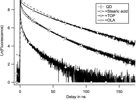
Fluorescence recovery
We have compared the effect of a dilution in toluene with the dilution in the three surfactants in order to indentify which ligand is responsible of the quenching. The fluorescence recovery upon the addition of ligand is summarized on figure 4. To a volume 0.1mL of the 41,5µmol/L of the QD solution, we have added the same volume of toluene, or 0.1mL of either TOP, or 0.1mL of oleylamine OLA or 0.1 mL of a solution of stearic acid SA at a concentration of (0.5mol/L) and we monitored the evolution of the fluorescence decay curves in the different cases. We can see that the effect of the addition of OLA is similar to that of the addition of toluene. OLA is not involved in the quenching. The addition of TOP reduces the quenching whereas the addition of stearic acid increases the quenching amplitude. This indicates that the quenching by dilution is due to the removal of TOP and possibly by its replacement by stearic acid.
Figure 4: Fluorescence decays after addition of solvent or of ligand: “◊” a solution of QDs at a concentration 20µmol/L; “o” same with stearic acid (final concentration of added SA 0.25 mol/L); “∇” same with TOP (1.1 mol/L); “x“ same with oleylamine (OLA) (1.5 mol/L). It can be seen that the presence of OLA has barely any effect on the decay curve. The fluorescence recovers upon the addition of TOP, whereas the addition of stearic acid SA induces a precipitation and an increased quenching. The measured decays are compared with the decays calculated (dotted lines) according to a Perrin model assuming that more quenching sites with the same quenching rate per site are created by the addition of SA. We can see that the addition of SA does increase the number of quenching sites but not the quenching rate per site.
The quenching by a small number of quenchers was first described by Perrin30 for the static part. Infelta31 and
Tachiya32 have treated the quenching dynamics the case of in micelles and recently for FRET quenching of QD15. Blumen
has predicted the transfer of energy of one fluorescent molecule to an ensemble of surrounding sites that are randomly occupied.17 This has been generalized by Klafter as a first passage time problem.33
Here we shall use the formalism of Blumen to describe the quenching by a few quenchers but we assume that the fluorescence decay per quencher in non exponential. This can be due for at least two reasons. First, one can assume that the sample is heterogeneous. The same exciton/quencher pair is supported by different QDs and this same pair reacts with different rates from QD to QD. Or one can assume that the hole part of the exciton is trapped after each excitation in different positions34, 35 and that exciton/quencher pair reacts with different rates depending on the position
of the hole. Each QD would be heterogeneous with respect to the quenching. In both cases the excitons differ by their position i in different QD or in different positions inside a QD. A few quenching sites labeled j∈[0,m] that are randomly occupied quench them.
The decay of one emissive site in position i is given by:
€
I
fiK(t) = I
fiK(0) exp −k
( )
ft
exp −
(
δ
jk
Qijt
)
j =1N
∏
(1)Where kQij is the quenching rate constant of a site in position i by a quencher in position j. δjequales 1 or 0 if the
quenching site j is active or not in the configuration K. kf is the fluorescence rate constant in the absence of
quenching.
The ensemble decay is the sum over all the possible K configurations of quenchers on the QD but also over all the positions i of the emissive site in the QDs.
€
I
f(t) = I
f(0) exp −k
(
ft
)
exp −
(
δ
jk
Qijt
)
j =1 m
∏
j∑
i∑
(2)The average decay of one K configuration of the quenchers over the i possible positions of the emissive site can be described as a time dependent rate coefficient.36
€
I
fK(t) = I
fK(0)exp(−k
ft)
exp(−δ
jk
Qijj =1 m
∏
i∑
t)
= I
fK(0)exp −k
ft − k
QK(u)du
o t∫
'
(
)
*
+
,
(3)For the configurations K with one quencher, we shall assume that the average rate coefficient is the same whatever the position of the quencher on the QD: kQ(t). For n quenchers the rates adds up to n.kQ(t).
€
I
fn(t) = I
fn(0)exp −k
ft − n k
Q(u)du
o t∫
$
%
&
'
(
)
(4)Let us assume that the maximum number of quenching sites is m, the same for all QD. (The case of a binomial distribution of m values is treated in reference 14 for the static quenching). The probability that a site is active for
quenching is p. The number of quenching sites per particle varies from 0 to m, leading to m+1 different populations of fluorescent QDs in proportions that follow the binomial distribution:
€
I
fn(0) = I
f(0)
m nC
p
n(1 − p)
m−n (5)From equation (4) and (5), the fluorescence decay of the total population will be:
€
I
f(t) = I
f(0)
m nC
n=o m∑
p
n(1 − p)
m −nexp −k
ft − n k
Q(u)du
o t∫
⎛
⎝
⎜
⎞
⎠
⎟
(6) Thus applying the binomial theorem, we can write:€
I
f(t)
I
f(0)
exp(k
ft) = 1 + p exp( k
o Q(u)du )
t
∫
−1
⎛
⎝
⎜
⎞
⎠
⎟
⎧
⎨
⎩
⎫
⎬
⎭
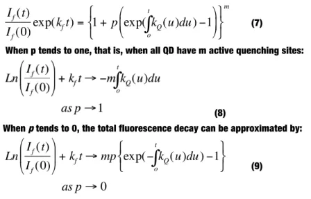
m (7)When p tends to one, that is, when all QD have m active quenching sites:
(8)
When p tends to 0, the total fluorescence decay can be approximated by:
€
Ln
I
f(t)
I
f(0)
⎛
⎝
⎜
⎞
⎠
⎟ + k
ft → mp exp(− k
Q(u)du
o t∫
) −1
⎧
⎨
⎩
⎫
⎬
⎭
as p → 0
(9)which is the formula obtained assuming a Poisson distribution of quenchers.37
We have demonstrated this formula in the case of immobile reactants. We show in the supplementary information that, in some cases, it can be applied to other type of reactions with time dependent rate coefficients such as diffusion limited reactions.
Data treatment
As long as p, the fraction of quenching sites remains low, the logarithm of the fluorescence decays should depend linearly on mp as shown by equation (9). We have applied a Principal Component Analysis to this linear problem19, 38
using the data analysis environment Igor Pro from Wavemetrics.39 The decays are considered as vectors in a space of
4096 dimensions. The algorithm is looking for an orthonormal base on which to express the data. The first component of the base is chosen to be the closest to the data. The data are then projected in the space orthogonal to that first vector and the successive elements of the base are constructed by recurrence. The fraction of the data described by each component is displayed in the inset of figure 5. The inset shows that the first two components are sufficient to properly describe the data. This is confirmed by the shape of the sum of components beyond the two firsts that is shown on figure 5. It is shapeless and contains only noise.
Figure 5: Theory predicts that the logarithm of the fluorescence decay in the case of the quenching by a Poisson distribution of quenchers will be the sum of two components. Indeed in inset are displayed the contributions of the components proposed for the description of the data. Only two have a significant contribution to the data. The sum of the
contribution of the discarded components is plotted as a dotted curve. It contains more noise than kinetics. Components with a physical meaning can be built as linear combinations of the components proposed by the main component analysis. One combination is chosen to be as close as possible to monoexponential decay (lozenge). It represents the fluorescence decay of QD without quencher. The second one is chosen to be flat at long times (square). This component is the decay dynamics of one site. It appears to be highly non-exponential.
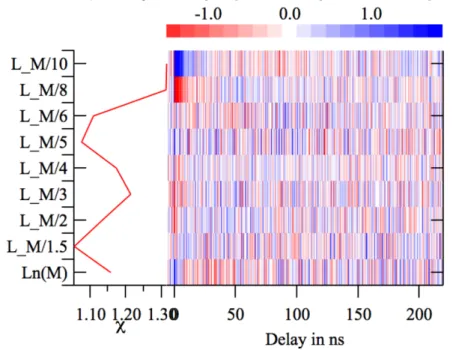
The quality of the description of the data by the two components is depicted by the weighted residuals on figure 6. The map made from the residuals of each curve exhibits a random change in sign. The χ2 of the adjustment of each
curve is close to one, showing that the quality of the description of the data by the two first components is very good.
Figure 6: The quality of the description of the data by the two components is shown. First the weighted difference between the data and their description is plotted in red white blue colour scale. It can be seen that points are randomly red or blue that means that the data are randomly above and below their description. One domain is not well described: the short time of the most diluted sample. The standard deviations of the weighted residuals are represented for each curve. It confirms that the two most diluted decays are less well described by the Poisson model.
We thus show that the logarithm of the decays can be described the sum of two curves: the quenchers add their actions and the decay rate coefficient of n quenchers is n∫kQ where ∫kQ states for ∫kQ(u)du. The next step is to extract the
unquenched component and the quenching component from the data. The two components that have been produced by the principal component analysis are not the two components predicted by the theory, but a linear combination of them. Any linear combination of the two main components will describe the data equally well. Thus we need to make additional hypothesis.
To describe the unquenched component, we have chosen a combination as close as possible to an exponential. We obtain a curve that describes the rise of the fluorescence during the excitation pulse and the exponential decay of the unquenched population with a lifetime of 45 ns that compares with the one measured on concentrated solutions. For the component ∫kQ that describes the quenching, we have chosen a combination that tends to a horizontal slope at long
time. This component represents the quenching rate per one quencher (equation (9)).
The adjustment of the decays on these two components exp(-kft) et ∫kQ(u)du according to equation (9) give us the
value for mp=<n>.
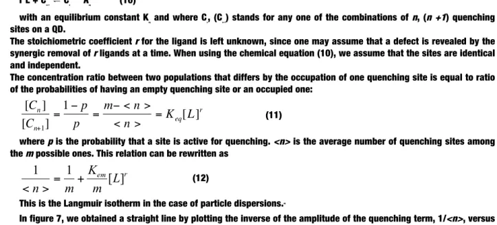
Thermodynamics of the formation of the quenching sites
As described in the previous section and using equation (9), we can extract the average number of quenchers per QD <n>=mp from the dilution analysis. Let us assume that the ligands L=(TOP or, OLA or ST) are in equilibrium between the solution (as free ligands) and the surface of the QDs (as bound ligands).
r L + Cn+1⇌ Cn Keq (10)
with an equilibrium constant Keq and where Cn, (Cn+1) stands for any one of the combinations of n, (n +1) quenching
sites on a QD.
The stoichiometric coefficient r for the ligand is left unknown, since one may assume that a defect is revealed by the synergic removal of r ligands at a time. When using the chemical equation (10), we assume that the sites are identical and independent.
The concentration ratio between two populations that differs by the occupation of one quenching site is equal to ratio of the probabilities of having an empty quenching site or an occupied one:
€
[C
n]
[C
n+1]
=
1 − p
p
=
m− < n >
< n >
= K
eq[L]
r (11)where p is the probability that a site is active for quenching. <n> is the average number of quenching sites among the m possible ones. This relation can be rewritten as
r em
L
m
K
m
n
[
]
1
1
+
=
>
<
(12)This is the Langmuir isotherm in the case of particle dispersions.40
In figure 7, we obtained a straight line by plotting the inverse of the amplitude of the quenching term, 1/<n>, versus the inverse of the dilution factor Vo/V. The free ligand concentration decreases with the dilution. First, we can see that the experimental data points align on a straight line when plotted versus (Vo/V). This indicates that r=1. Thus a quenching defect is due to the removal of one single ligand. Second, the concentration of free ligands follows linearly the dilution. This means that the large majority of ligands are tightly bound to the surface of the QD and do not feed the solution in free ligands during the dilution. Third the intercept of the fitted straight line with the Y-axis gives a value of m=2.97±0.1. Thus up to 3 quenching sites per QD can be rendered active under our experimental conditions. This is 3 out of 13 TOP per QD on average as was measured by NMR.41 This is much less than the 37 quenching sites
measured in the case of CdSe in chloroform.16 This could be only a fraction of the total ligand released, if the other
ligands are released from sites that do not induce a quenching.
Figure 7: The average number of quenching site obtained from the amplitude of the quenching in decays is represented versus the inverse of the dilution factor according to a Langmuir model. The dotted curve is an adjustment with a free stoichiometric parameter r found equal to 0.8±0.1. The straight lime is an adjustment with stoichiometric parameter r=1. The point alignment shows that the creation of one quenching site is due to the removal of one ligand and that the maximal number of quenching sites is 2.97±0.1.
The concentrations of the free ligands have been measured by NMR. They are gathered in table 1. From the slope of the fit in figure 7, we can deduce an average affinity constant of all three ligands of 1600L/mol. This in good agreement with the results obtained by other groups, taking into account that in our case the ligand shell is composed of three different ligands.16
Kinetics of the quenching
From the data treatment part, we get the shape of the time dependant rate ∫kQ of the quenching by one site. When all
the QD present the same, maximum, number of quenching sites, the decay rate of the solution will be m∫kQ. This is
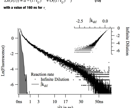
shown by equation (8). Indeed the logarithm of the decay recorded for a solution diluted 100 times in toluene is compared to the decay rate obtained from the analysis of the first steps of the dilution in Figure 8. The scaling factor can be obtained from the plot shown in the inset where the two time functions are plotted one versus the other for all values of the time. We measure for m the maximum number of quenching sites a value of m=2.88±0.02. This confirms the value obtained by the previous thermodynamic analysis. This also validates the assumption made in the data treatment part that ∫kQ is zero at long time.
The two rates are compared after scaling in figure 8. We plot them versus √(time). The figure shows that Ln(I(t)) scales as √t at short times:
€
Ln(I(t)) = a − (t /
τ
Q)
1/ 2+ O((t /
τ
Q)
3 / 2)
(13)with a value of 160 ns for τ Q.
Figure 8: The quenching rate per quenching site ∫kQ obtained from the Poisson distribution analysis can be compared with
the quenching rate at high dilution where all quenching sites are active on all QDs. In inset, the parametric plot of the rates shows that the quenching rate at high dilution is 2.88±0.02 faster than the rate per quenching sites. This perfectly agrees with the number of quenching site deduced from the Langmuir analysis. In the figure the normalized quenching rates have been displayed as a function of √(t) together with the instrument response function (in grey).
We can discard some hypothesis about what is the process that responsible of the fluorescence decay. We have compared the decay obtained in 1.1 mol/L of SA with the decay expected from an increase of the number of quenching sites with the same quenching rate per site (figure 4). We see that the observed decay is not faster than the predicted one. The addition of SA has increased the number of quenching sites but the rate per site remains the same. The
reaction responsible of the quenching cannot be the diffusion of stearic acid molecules from the solution toward a TOP free site, since the rate per site after the addition of stearic acid is not faster.
It should also not be a diffusion of a TOP molecule out of a quenching site induced by the excitation of the nanoparticles since this diffusion would scale as 1/tdim if it diffuses freely into the surfactant layer or toluene.18 The
reaction responsible for the formation of the quenching site thus is not the reaction responsible for the quenching kinetics. The removal of a TOP acts as a tap that opens a deactivation pathway but ligands do not participate to the quenching step.
It cannot be a fast charge trapping, a process by which the electron or hole is transferred from its initial delocalized excitonic state to a state localized on a surface atom occurring at short time followed by a slow (ns) tunnelling. Indeed the deactivation of the trapped exciton would not be faster if more than one surface traps are made available whereas we show that each quenching site adds a new decay channel for the exciton. The Perrin dependence on the number of quencher shows that the surface states add their reactivity. Thus the surface defect is one of the reactants of the reaction responsible of the non radiative decay (recombination).
The √t dependence shows that we have a distribution of quenching rates. This reveals a heterogeneous environment: the rate of reaction of the exciton with the surface defects varies either from QD to QD or inside a QD. The mechanism by which this reaction occurs or the origins of the heterogeneity are beyond the scope of this contribution. Indeed the √t kinetics that we measure could be that of a Brownian diffusion of a mobile quencher42, or an energy
transfer through a dipolar coupling.18
In conclusion, we have been able to decrypt the complexity of the fluorescence decays of CdSe QDs during a dilution experiment thanks to the proportionality between the rate coefficient and the average number of quenchers. We have successfully used a principal component analysis that shows that up to 3 quenching sites appear upon dilution of dispersion of our QDs dispersion. The quenching sites are created by the release of TOP molecules one by one. The number of quenching sites is obtained independently from a Langmuir isotherm and from the kinetics study of the decay curves. In addition to a binomial distribution of the quenchers, we show that the quenching dynamics scales as √t. The nature of the surface defects and the mechanism of the reaction of the quenching sites with the exciton remain unknown.
EXPERIMENTAL METHODS:
Synthesis and characterization of the CdSe QDs. Spherical CdSe QDs (diameter ≈ 4,8 nm) were synthesized using a 2-L reactor according to the procedure described in references 1, 41. In brief, 8 mmol of cadmium stearate
CdSt2, 184 mmol of SA, 0.85 mol (280 mL) of oleylamine (OA) and 186 mL of 1-octadecene (ODE) are introduced in the
2-L reactor which is thereafter degassed for 45 min filled with argon and heated to 250°C. Then 100 mL of a 0.4 M TOP-Se solution are injected within 1s using a peristaltic pump with a strong vortex mixing. The mixture is maintained at 250°C for 15 min and then the heating source (molten salt or graphite flakes bath) is removed. The obtained CdSe QDs are purified by first adding acetone (500 mL) then methanol (200mL) and again 300 mL of acetone. The reactor is maintained overnight at 70°C. This allows keeping the stearic acid in its liquid phase (melting temperature around 70°C) whilst the QDs precipitate at the bottom of the reactor. At the end of this step, the supernatant is removed and the precipitated QDs are recovered and redispersed in hexane. Two further steps of purification by addition of methanol then centrifugation and redispersion are performed before using the QDs. For all the experiments presented in this work, we used colloidal dispersion of QDs in toluene (or toluene-d8 for the NMR analysis, see below) as the
solvent. The QDs are covered by a ligand shell composed of a mixture of trioctylphosphine (TOP), oleylamine(OA) and stearate (SA) whose average composition was analyzed using solution nuclear magnetic resonance spectroscopy (NMR) techniques (vide supra).
The absorption spectrum of the QDs shows an excitonic peak with its maximum at 602 nm which corresponds to a diameter of 4.8 nm using the relation provided in ref.27, see Figure S1. This is in excellent agreement with the average
QD size, as derived from transmission electron microscopy (TEM, data not shown). The size polydispersity as derived from TEM is around 13,3%. The fluorescence spectrum of the QDs peaks at λ = 620 nm with a full-width-at half maximum (FWHM) of 36 nm. Powder X-ray diffraction of the QDs (data not shown) confirms the hexagonal wurtzite structure of the QDs.
High resolution liquid state NMR characterization of the composition of the ligand shell covering the QDs. The composition of the ligand shell was analyzed and quantified using 1H nuclear magnetic resonance
5 mm BBI-xyz-gradient probe. The spectra were recorded in toluene-d8 at 298 K. Typical concentrations of the QD
dispersions used for the NMR analysis are about 10 to 100 µM as determined from the UV-vis absorption spectra27. For
the quantification of the composition of the ligand shell, CH2Br2 was used as an internal concentration standard. We
systematically used a digital integration of the resonance lines of 1H-NMR relaxed spectra (recycling time of 45 s) after
baseline correction with the WIN-NMR software (Bruker Biospin, Wissembourg, France). Based on this quantification and on the concentration of CdSe QDs from the UV-vis spectra, we can estimate the average number of ligands per QD as well the ligand density.
In Pulsed field gradient (PFG) 1H-NMR mode, one can measure the diffusion coefficient D of a species by monitoring
the attenuation of related NMR peaks when applying variable magnetic field gradients 24, 26. The diffusion filtered spectra
were recorded with the standard bipolar LED pulse sequence, δ=2ms and Δ=150 ms. The amplitude of the trapezoidal gradient pulses was varied from 5 to 90% of the maximum amplitude of 50.5 G.cm-1. The attenuation of the peaks
follows the Stejskal-Tanner equation:
(
)
(
)
(
/
3
/
2
)
exp
2 0τ
δ
δ
γ
Δ
−
−
−
=
g
D
I
I
H (14)where D is the self-diffusion coefficient of the species considered, γH is the proton gyromagnetic ratio, g and δ are
the gradient pulse strength and duration, respectively, Δ the diffusion delay and finally τ is the time interval between the bipolar gradient pulses . To calculate the hydrodynamic diameter dH from the diffusion coefficient D, we used the
Stokes-Einstein formula
D
T
k
d
B Hπη
3
=
(15)where kB is the Boltzmann constant and taking η = 0.55 × 10
-3 kg s-1.m-1 for the value of the dynamic viscosity of
toluene at 298 K.
Instrument. The single photon counting set up has been described elsewhere.43 It uses a Tsunami titanium- doped
sapphire laser from Spectra Physics and a multichannel plate photo- multiplier (R3809U Hamamatsu Massy, France). Characterization. UV-vis absorption spectra were acquired on a Carry 5000 spectrophotometer. The photoluminescence spectra were obtained using a Fluorolog III spectrometer. Transmission electron microscopy imaging of the NCs was performed using a Jeol 4000 EX microscope at 400 keV operated in bright field mode.
SUPPORTING INFORMATION:
The UV-Vis absorption and photoluminescence spectra of the CdSe QDs can be found in the supplementary materials. Also included are a binomial analysis of the non quenched population and a discussion about the difference between mobile quenchers and mobile fluorescent sites in the case of Perrin quenching. This material is available free of charge via the Internet at http://pubs.acs.org.
AUTHOR INFORMATION Corresponding Author
* [email protected] Author Contributions
The manuscript was written through contributions of all authors. / All authors have given approval to the final version of the manuscript. / ‡These authors contributed equally. (match statement to author names with a symbol)
Funding Sources
This work was supported by the French National Research Agency ANR through the MYOSOTIS project (grant N°ANR-08-NANO-012-01).
Acknowledgments:
Graphical Table of Content
REFERENCES
1. Protiere, M.; Nerambourg, N.; Renard, O.; Reiss, P., Rational design of the gram-scale synthesis of nearly monodisperse semiconductor nanocrystals. Nanoscale research letters 2011, 6, 472.
2. Rogach, A. L., Semiconductor Nanocrystal Quantum Dots: Synthesis, Assembly, Spectroscopy and Applications. Springer Verlag: Wien, 2008.
3. Mei, B. C.; Wang, J.; Qiu, Q.; Heckler, T.; Petrou, A.; Mountziaris, T. J., Dilution effects on the photoluminescence of ZnSe quantum-dot dispersions. Applied Physics Letters 2008, 93, 083114.
4. Al Salman, A.; Tortschanoff, A.; van der Zwan, G.; van Mourik, F.; Chergui, M., A model for the multi-exponential excited-state decay of CdSe nanocrystals. Chemical Physics 2009, 357, 96-101.
5. Talapin, D. V.; Rogach, A. L.; Kornowski, A.; Haase, M.; Weller, H., Highly Luminescent Monodisperse CdSe and CdSe/ZnS Nanocrystals Synthesized in a Hexadecylamine−Trioctylphosphine Oxide−Trioctylphospine Mixture. Nano Letters 2001, 1, 207-211.
6. Knowles, K. E.; McArthur, E. A.; Weiss, E. A., A Multi-Timescale Map of Radiative and Nonradiative Decay Pathways for Excitons in CdSe Quantum Dots. ACS Nano 2011, 5, 2026-2035.
7. Koposov, A. Y.; Szymanski, P.; Cardolaccia, T.; Meyer, T. J.; Klimov, V. I.; Sykora, M., Electronic Properties and Structure of Assemblies of CdSe Nanocrystal Quantum Dots and Ru-Polypyridine Complexes Probed by Steady State and Time-Resolved Photoluminescence. Advanced Functional Materials 2011, 21, 3159-3168.
8. Loumaigne, M.; Richard, A.; Laverdant, J.; Nutarelli, D.; Débarre, A., Ligand-Induced Anisotropy of the Two-Photon Luminescence of Spherical Gold Particles in Solution Unraveled at the Single Particle Level. Nano Letters 2010, 10, 2817-2824.
9. Jones, M.; Lo, S. S.; Scholes, G. D., Signatures of Exciton Dynamics and Carrier Trapping in the Time-Resolved Photoluminescence of Colloidal CdSe Nanocrystals. J. Phys. Chem. C 2009, 113, 18632-18642.
10. Kern, S. J.; Sahu, K.; Berg, M. A., Heterogeneity of the Electron-Trapping Kinetics in CdSe Nanoparticles. Nano Lett. 2011, 11, 3493-3498.
11. Koole, R.; Schapotschnikow, P.; de Mello Donegá, C.; Vlugt, T. J. H.; Meijerink, A., Time-Dependent Photoluminescence Spectroscopy as a Tool to Measure the Ligand Exchange Kinetics on a Quantum Dot Surface. ACS Nano 2008, 2, 1703-1714.
12. Priyam, A.; Bhattacharya, S. C.; Saha, A., Volatile interface of biological oxidant and luminescent CdTe quantum dots: implications in nanodiagnostics. Physical Chemistry Chemical Physics 2009, 11, 520-527.
13. Bullen, C.; Mulvaney, P., The effects of chemisorption on the luminescence of CdSe quantum dots. Langmuir : the ACS journal of surfaces and colloids 2006, 22, 3007-13.
14. Morris-Cohen, A. J.; Vasilenko, V.; Amin, V. A.; Reuter, M. G.; Weiss, E. A., Model for Adsorption of Ligands to Colloidal Quantum Dots with Concentration-Dependent Surface Structure. ACS Nano 2012, 6, 557–565.
15. Sadhu, S.; Tachiya, M.; Patra, A., A Stochastic Model for Energy Transfer from CdS Quantum Dots/Rods (Donors) to Nile Red Dye (Acceptors). J. Phys. Chem. C 2009, 113, 19488-19492.
16. Morris-Cohen, A. J.; Frederick, M. T.; Cass, L. C.; Weiss, E. A., Simultaneous Determination of the Adsorption Constant and the Photoinduced Electron Transfer Rate for a Cds Quantum Dot-Viologen Complex. Journal of the American Chemical Society 2011, 133, 10146-10154.
17. Blumen, A., Excitation transfer from a donor to acceptors in condensed media: a unified approach. Il Nuovo Cimento B (1971-1996) 1981, 63, 50-58.
19. Ruckebusch, C.; Sliwa, M.; Pernot, P.; de Juan, A.; Tauler, R., Comprehensive data analysis of femtosecond transient absorption spectra: A review. Journal of Photochemistry and Photobiology C: Photochemistry Reviews 2012, 13, 1-27.
20. Green, M., The nature of quantum dots capping ligands. J. Mater. Chem. 2010, 20, 5797-5809.
21. Gomes, R.; Hassinen, A.; Szczygiel, A.; Zhao, Q. A.; Vantomme, A.; Martins, J. C.; Hens, Z., Binding of Phosphonic Acids to CdSe Quantum Dots: A Solution NMR Study. J Phys Chem Lett 2011, 2, 145-152.
22. Hassinen, A.; Moreels, I.; Donega, C. D.; Martins, J. C.; Hens, Z., Nuclear Magnetic Resonance Spectroscopy Demonstrating Dynamic Stabilization of CdSe Quantum Dots by Alkylamines. J Phys Chem Lett 2010, 1, 2577-2581.
23. Fritzinger, B.; Capek, R. K.; Lambert, K.; Martins, J. C.; Hens, Z., Utilizing self-exchange to address the binding of carboxylic acid ligands to CdSe quantum dots. J Am Chem Soc 2010, 132, 10195-201.
24. Moreels, I.; Fritzinger, B.; Martins, J. C.; Hens, Z., Surface chemistry of colloidal PbSe nanocrystals. J Am Chem Soc 2008, 130, 15081-6.
25. Ji, X. H.; Copenhaver, D.; Sichmeller, C.; Peng, X. G., Ligand bonding and dynamics on colloidal nanocrystals at room temperature: The case of alkylamines on CdSe nanocrystals. Journal of the American Chemical Society 2008, 130, 5726-5735.
26. Hens, Z.; Moreels, I.; Martins, J. C., In situ 1H NMR study on the trioctylphosphine oxide capping of colloidal InP nanocrystals. Chemphyschem : a European journal of chemical physics and physical chemistry 2005, 6, 2578-84.
27. Jasieniak, J.; Smith, L.; Embden, J. v.; Mulvaney, P.; Califano, M., Re-examination of the Size-Dependent Absorption Properties of CdSe Quantum Dots. The Journal of Physical Chemistry C 2009, 113, 19468-19474.
28. Knowles, K. E.; Frederick, M. T.; Tice, D. B.; Morris-Cohen, A. J.; Weiss, E. A., Colloidal Quantum Dots: Think Outside the (Particle-in-a-)Box. The Journal of Physical Chemistry Letters 2011, 3, 18-26.
29. Schoutteten, L.; Denjean, P.; Pansu, R. B., Photophysics of "Calcium Green 1" in vitro and in live cells. PCCP 1999, 1, 2463-2469.
30. Perrin, F., quenching de concentration. Comptes rendus de l'académie des sciences 1924, 178, 1978.
31. Infelta, P. P.; Gratzel, M.; Thomas, J. K., Luminescence decay of hydrophobic molecules solubilized in aqueous micellar systems - kinetic-model. Journal of Physical Chemistry 1974, 78, 190-195.
32. Murata, S.; Tachiya, M., Refined Perrin equation for the analysis of fluorescence quenching by electron transfer. Chemical Physics Letters 1992, 194, 347-350.
33. Bénichou, O.; Chevalier, C.; Klafter, J.; Meyer, B.; Voituriez, R., Geometry-controlled kinetics. Nature chemistry 2010, 2, 472-7.
34. Guyot-Sionnest, G.-S., Philippe; Shim, M.; Matranga, C.; Hines, M., Intraband relaxation in CdSe quantum dots. Phys Rev B 1999, 60, R2181-R2184.
35. Klimov, V. I.; McBranch, D. W.; Leatherdale, C. A.; Bawendi, M. G., Electron and hole relaxation pathways in semiconductor quantum dots. Phys Rev B 1999, 60, 13740-13749.
36. Berberan-Santos, M. N.; Bodunov, E. N.; Valeur, B., Mathematical functions for the analysis of luminescence decays with underlying distributions 1. Kohlrausch decay function (stretched exponential). Chemical Physics 2005, 315, 171-182.
37. Bales, B. L.; Almgren, M., Fluorescence quenching of pyrene by copper(II) in sodium dodecyl-sulfate micelles - Effect of micelle size as controlled by surfactant concentration. Journal of Physical Chemistry 1995, 99, 15153-15162.
38. Abdi, H.; Williams, L. J., Principal component analysis. Wiley Interdisciplinary Reviews: Computational Statistics 2010, 2, 433-459.
39. http://www.wavemetrics.com/
40. Atkins, P. W., Physical Chemistry. 4 ed.; Oxford University Press: Oxford, 1992; Vol. 1, p 995.
41. Hartmann, L. Elaboration et étude de matériaux hybrides orientés et nanostructurés d’intérêt pour l’électronique organique. Université de Strasbourg, 2012.
42. Torney, D. C.; McConnell, H. M., Diffusion-Limited Reaction-Rate Theory for Two-Dimensional Systems. P Roy Soc Lond a Mat 1983, 387, 147-170.
43. Schoutteten, L.; Denjean, P.; Joliff-Botrel, G.; Bernard, C.; Pansu, D.; Pansu, R. B., Developement of Measurement of Intracellular Calcium by Time-Resolved Photon Counting Fluorescence. Photochemistry Photobiology 1999, 70, 701-9.
![Figure 1 A: 1 H NMR spectra of a CdSe QD solution ([QDs] = 62,5 µM) and of the free ligands in toluene-d 8](https://thumb-eu.123doks.com/thumbv2/123doknet/13440463.409674/4.918.103.803.567.724/figure-nmr-spectra-cdse-solution-qds-ligands-toluene.webp)