HAL Id: hal-02010328
https://hal.archives-ouvertes.fr/hal-02010328
Submitted on 15 Feb 2019
HAL is a multi-disciplinary open access
archive for the deposit and dissemination of
sci-entific research documents, whether they are
pub-lished or not. The documents may come from
teaching and research institutions in France or
abroad, or from public or private research centers.
L’archive ouverte pluridisciplinaire HAL, est
destinée au dépôt et à la diffusion de documents
scientifiques de niveau recherche, publiés ou non,
émanant des établissements d’enseignement et de
recherche français ou étrangers, des laboratoires
publics ou privés.
A Geometry-aware framework for compressing 3D mesh
textures
Fatemeh Nasiri, Navid Mahmoudian Bidgoli, Frédéric Payan, Thomas Maugey
To cite this version:
Fatemeh Nasiri, Navid Mahmoudian Bidgoli, Frédéric Payan, Thomas Maugey. A Geometry-aware
framework for compressing 3D mesh textures. ICASSP 2019 - IEEE International Conference on
Acoustics, Speech, and Signal Processing, May 2019, Brighton, United Kingdom. pp.4015-4019,
�10.1109/ICASSP.2019.8683258�. �hal-02010328�
A GEOMETRY-AWARE FRAMEWORK FOR COMPRESSING 3D MESH TEXTURES
Fatemeh Nasiri
?Navid Mahmoudian Bidgoli
?Fr´ed´eric Payan
†Thomas Maugey
??
Inria, Univ Rennes, CNRS, IRISA, Rennes, France
†Universit´e Cˆote d’Azur, CNRS, I3S, Sophia Antipolis, France
ABSTRACT
This paper proposes a novel prediction tool for improving the compression performance of texture atlases. This algorithm, called Geometry-Aware (GA) intra coding, takes advantage of the topology of the associated 3D meshes, in order to reduce the redundancies in the texture map. For texture processing, the concept of the conventional intra prediction, used in video compression, has been adapted to consider neighboring infor-mation on the 3D surface. We have also studied how this pre-diction tool can be integrated into a complete coding solution. In particular, a block scanning strategy and a graph-based transform for residual coding have been proposed. Results show that the knowledge of the mesh topology significantly improves the compression efficiency of texture atlases1.
Index Terms— Intra prediction, 3D mesh, texture map
1
Introduction
With the recent development of 3D scanning technologies, 3D models have been finely detailed. This has made the 3D repre-sentation a trending media format for novel applications, such as architectural or historical artifacts presentation, virtual re-ality, etc [1, 2, 3, 4]. As a result, the ability to transmit them easily through networks has attracted great attention in both academia and industry. 3D models commonly consist of a mesh, with geometry information (3D vertices) and its corre-sponding topology (connectivity among elements), as well as optional attribute information such as normals, colors, etc. To make the rendering more realistic, usually, 2D texture maps such as the diffusion, specular and bump maps are applied on mesh surface to present material properties, high frequency details, etc.
The compression of 3D mesh has been widely studied. A survey of such methods can be found in [5]. While the com-pression of textures from the perspective of rendering systems has been thoroughly studied [6, 7], the texture compression from the perspective of transmission or storage is almost over-looked. The former aims at compressing the texture maps to
1This work was partly supported by a GdR-Isis grant and the Cominlabs
excellence laboratory and managed by the National Research Agency in the ”Investing for the Future” program with reference ANR-10-LABX-07-01.
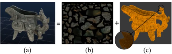
(a) (b) (c) Fig. 1. (a) A realistic 3D model consists of (b) texture infor-mation, mapped onto a (c) triangular mesh.
reduce the memory usage at the run-time and to provide the ability to render directly from the compressed textures loaded in rendering systems. The latter compresses the texture for storage and transmission, i.e. to reduce download or disk size. This paper proposes a new framework to compress the texture maps in order to reduce the storage size more efficiently than the traditional methods.
Traditional still image compression schemes, such as JPEG, are often used for storing texture maps [8]. Although such approaches may provide up to 50:1 compression rate [7], they are still less efficient than the conventional intra coding used in video compression standards [9]. To further exploit spatial redundancies, the conventional intra coding methods partition an image into blocks, and use parts of already coded adjacent blocks as references to predict the current block. Afterward, the residual signal between the original block and the predicted block is represented in the transform domain to remove the remaining correlation. Examples of intra cod-ing algorithm integrated in video compression standards can be found in Advanced Video Coding (AVC) [10] and High Efficiency Video Coding (HEVC) [11].
Adjacent parts of the 3D mesh might not be adjacent in the associated 2D texture maps, even though the texture on the surface of an object seems continuous. An example of 3D model, decomposed into geometry and texture information, is shown in Fig. 1. As can be seen, the texture information can be split into several disconnected patches in a 2D atlas. Con-sequently, blocks on the patch borders have non-informative neighbors (i.e. black areas between the patches). For instance, for block C in Fig. 2, none of the conventional neighboring blocks, namely A and B contains proper texture information for its prediction. Therefore, traditional intra coding methods would result in a poor prediction accuracy.
A
B C
Fig. 2. The blocks A and B around the border block C are non-informative references.
and available at the decoder. So, we exploit it for finding more relevant references for texture prediction. To this end, for the regions where the conventional reference block is non-informative, such as Fig. 2, the texture information of adja-cent areas on the 3D surface is used (Section 2). Due to the fact that the texture consists of several disconnected regions, we also propose a block scanning method based on the knowl-edge of the mesh surface as an alternative to the regular raster scanning (Section 3). Moreover, a graph transformation is proposed to decorrelate the residual signal of blocks on the border of patches (Section 4).
2
Geometry-aware intra prediction
2.1
Conventional intra prediction
From high level point of view, intra prediction is a predefined modeling tool with several internal modes that are adjusted with its parameters. These parameters determine texture pat-tern to be produced by reference pixels from previously coded blocks. Depending on the parameter setting, the selected pat-tern can either be directional or plain. For example, HEVC uses one row and one column of references (i.e. from the left and to the above of a block) to apply a prediction model with 35 internal modes, including the DC, the Planar and 33 angu-lar modes.
In our context, the conventional intra prediction is not able to distinguish between informative and non-informative parts of a texture atlas. Therefore, its use for texture compression produces high energy residual signals on blocks which are po-sitioned on patch borders. This poor prediction performance is due to the inaccuracy of non-informative references. In or-der to address this problem, the topology of the mesh is pro-posed to be utilized for finding more correlated references for intra prediction. However, for the texture modeling step, we adopt the same set of 35 intra modes of HEVC.
2.2
Proposed intra prediction
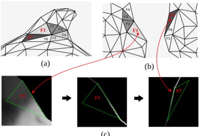
Discrete patches on texture atlas can be mapped to continuous 3D texture using mesh triangles, as shown in Fig. 3-(a). The algorithm proposed in this paper uses this information to fill the empty set of references, when the block is positioned on a patch border (Fig. 3-(b)). For this purpose, first, the neighbors of a border block are detected using the mesh connectivity.
F2 F6 F5 F4 F3 F3 F2 F6 F5 F4 (a) (b) F1 F7 F7 F1 F1 F1 F7 (c)
Fig. 3. Process of copying border references from remote neighbors. A 3D mesh in (a) is mapped into a 2D atlas in (b). According to this mapping, the block F7 can be used as the remote neighbor of F1, hence, its interior border is copied to the exterior border of F1 (c).
Then, if they are already coded, their border pixels are copied to fill the references of the current block. Such neighbors might be remote on the 2D texture atlas, yet, adjacent on the 3D mesh.
Fig. 3-(c) shows how the proposed algorithm copies the inner border of remote triangles on the border of the cur-rent triangle. In some inevitable cases, the proposed refer-ence copying is not possible, since the remote neighbor is not coded yet.
The references that were replaced on the border of the patches with such an approach are irregularly positioned. This is in contrary with the conventional intra prediction algorithm, where the references are regularly placed on the top row and left column. This makes the conventional block prediction challenging. For instance, the block prediction algorithm of HEVC performs a backward projection along with a linear interpolation on the reference pixels in order to produce the prediction values within the block [12]. The formulation of this process requires the reference pixels to be aligned in one row and one column.
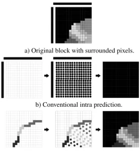
To address the above problem, our algorithm integrates a forward reference projection, instead of the regular backward one. This process is shown in Fig. 4 and consists of two steps: 1) forward projection of reference pixels on non-integer positions within a block, 2) interpolation of integer positions using up to four non-integer neighbors. For comparison, Fig. 4 also shows the resulting prediction with the conventional intra prediction algorithm on a border block.
3
Geometry-aware block scanning
The use of remote references on border blocks makes the reg-ular raster scanning of blocks inefficient. Indeed, the scan-ning may require access to remote references that are not yet coded. As discussed, this problem is inevitable due to
in-a) Original block with surrounded pixels.
c) Proposed intra prediction with irregular references. b) Conventional intra prediction.
Fig. 4. Block prediction of a border block. Left: set of ref-erence samples. Middle: propagation of refref-erence samples (reference projection). Right: intra prediction (interpolation). complete data access on the 2D atlas. However, its frequency of occurrence can significantly be reduced by using a smart block scanning that takes advantage of mesh connectivity.
The proposed scanning algorithm starts from an initial block that contains the geometric centroid of the largest patch on the 2D atlas. Once the initial block is coded, its neighbor-ing blocks are checked to choose the next block to be coded. For this purpose, two rules are applied to prioritize neighbor-ing blocks:
Rule 1: Candidates with higher number of available neigh-boring blocks have a higher priority.
Rule 2: Among candidates with the same number of available references, those with available reference blocks at above and left have higher priority.
Starting from the centroid, all blocks within the first patch (i.e. largest patch) can apply the conventional intra prediction algorithm. The only exception is that sometimes, we may have to use a reference row and a column at bottom and right, respectively. For these blocks, one can simply rotate the block as well as its references, in order to put the reference row and column on their right position. Then, the conventional algorithm can be applied to any block in the first patch. Even the border blocks.
Once all the blocks within the first patch are scanned, the next step is to scan the next patch. To do so, we first detect the triangles positioned on the border of the first patch. Then, their remote neighbor triangles are found in other patches, by using the 3D mesh. In the proposed scanning method, the next patch is selected as the one with the most neighboring pixels on the border.
4
Geometry-aware residual coding with
graph transform
Conventional residual coding methods usually use the Dis-crete Cosine Transform (DCT) to compact the information for transmission. Despite its numerous benefits, applying the DCT on the residual signal of border blocks is not efficient. This is due to the fact that the informative part of border resid-ual blocks is not square, and this would result in a large energy on the coefficients in higher frequencies. To address this prob-lem, our geometry-aware residual coding method utilizes the mesh connectivity and detects border blocks to apply a graph-based transform on their residual, called the Graph Fourier Transform (GFT) [13, 14, 15].
Once a border block with the size of BS× BSis predicted
and its residual signal R is calculated, the GFT is performed with the following steps:
Step 1) Constructing a graph for each border block based on its residual data R. Moreover, a mask M is reconstructed from the geometry information of the block to contain its informative pixels coordinates.
Step 2) Forming an undirected connected graph G = {V, E, A} from the masked residual, which consists of a finite number of vertices corresponding to the residual data at position {i, j}, i, j = 1 . . . BS, such that M (i, j) = 1. The set E of
edges is formed by using four neighbors around each residual value.
Step 3) Constructing an adjacency matrix A from the edges in G.
Step 4) Calculating the degree of each node and construct matrix D as a diagonal degree matrix whose i-th diagonal el-ement is equal to the sum of the weights of all edges incident to node i.
The subtraction of matrix A from D form the Laplacian matrix L:
L = D − A, (1) where L is a symmetric semi-definitive matrix and can be di-agonalized as:
L = UTΛU, (2) where U is the matrix of eigen-vectors and the diagonal ma-trix Λ consists of eigenvalues. The mama-trix U is used to com-pute the unweighted GFT coefficients as:
ˆ
R = UR, (3) and the inverse is computed as:
R = UTR.ˆ (4) One interest of GFT is that its number of coefficients is equal to the number of informative coordinates in the input residual R. These coefficients are normally quantized and coded using a proper arithmetic coding.
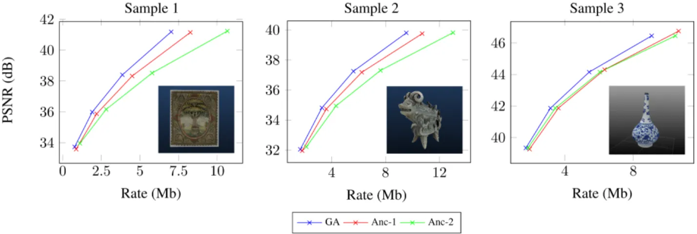
Fig. 5. Rate-PSNR curves of the proposed algorithm (GA) against two configurations of the anchor (Anc) on 3 diffusion maps.
5
Experimental Results
We have implemented all the proposed tools in a complete coding solution. This section presents its compression perfor-mances in different conditions. The input data comes from [16], which consists of three ancient objects with different maps ( normal, diffusion etc.). In this experiments, only the diffusion maps that represents the “natural” texture of object are tested.
The proposed Geometry-Aware (GA) algorithm is com-pared against the conventional intra prediction as the anchor, in terms of Bjontegaard Delta Rate (BD-R) [17]. For this pur-pose, different configurations were considered for the anchor algorithms. The first configuration (Anc-1) uses the raster scanning and the conventional intra prediction, but applies the GFT on border blocks and the Peak Signal-to-Noise Ration (PSNR) has been calculated only on the informative pixels of the atlas. The second anchor (Anc-2) performs similarly to Anc-1, except that it uses the DCT instead of the GFT on the border blocks.
For simplicity and without loss of generality, the perfor-mance evaluation has been carried out under two conditions. First, a united entropy coder based on arithmetic coding has been shared between the proposed and the anchor methods. This entropy coder allows rate calculation of individual syn-tax elements as well as an entire sequence. Second, a fixed block size partitioning has been used in each configuration. In other words, for each comparison, the entire 2D atlas has been coded with a constant block size. However, the results are provided as the average BD-R gain over different block sizes, namely 16×16, 32×32 and 64×64.
Table 1 compares the defined configurations of the pro-posed algorithm GA against the two anchor methods, in terms of BD-R. Each negative value indicates the percent-age of compression gain achieved by the “GA” configuration against the “Anc” configuration of the corresponding column, when applied on the 3D sample of the corresponding row.
Moreover, Fig. 5 demonstrates the rate-distortion curves of different configurations on each test sample. As can be seen, a promising compression gain can be achieved by using the proposed geometry-aware intra coding tools.
Our GA encoding scheme is more complex than the an-chors. However, it is not a problem as free view-point ap-plications support asymmetrical compression-decompression scheme (compress once, decompress many).
Table 1. Performance comparison of the the proposed GA algorithm against, two anchors, in terms of BD-R (%).
Sample Anc-1 Anc-2 Sample-1 -16.1% -29.6% Sample-2 -11.0% -23.2% Sample-3 -17.3% -19.4%
6
Conclusion and future work
In this work, we propose a framework for compressing tex-ture atlases of 3D models. Conventional image compression methods treat atlas of 3D objects simply as 2D signals and do not benefit from their geometry information. In this pa-per, a pixel prediction method with a proper reference selec-tion and block scanning strategy and an alternative residual transformation are integrated in the conventional intra coding algorithm.
As a future work, one can integrate the proposed al-gorithm within existing codecs, such as HEVC test Model (HM), in order to evaluate its coding performances on texture maps. This would require normative changes in all three domains of prediction, scan and residual coding. Such ex-periment provides allows benefiting from highly optimized tools of HEVC, such as Context Adaptive Binary Arithmetic Coding (CABAC), residual coding, flexible block partitioning etc.
7
References
[1] “Open heritage: Google art and culture,” https://artsandculture.google.com, Accessed: 2018-10-29.
[2] Bailin Yang, Xun Wang, Frederick WB Li, Binbo Xie, Xiaohui Liang, and Zhaoyi Jiang, “3D mesh compres-sion and transmiscompres-sion for mobile robotic applications,” International Journal of Advanced Robotic Systems, vol. 13, no. 1, pp. 9, 2016.
[3] Yuan Gao, Yunhui Shi, Shaofan Wang, Wenpeng Ding, Jin Wang, and Baocai Yin, “Realistic 3D mesh com-pression based on predicted angle-normal images,” in Data Compression Conference (DCC), 2016, 2016, pp. 595–595.
[4] Jingliang Peng, Chang-Su Kim, and C-C Jay Kuo, “Technologies for 3D mesh compression: A survey,” Journal of Visual Communication and Image Represen-tation, vol. 16, no. 6, pp. 688–733, 2005.
[5] Adrien Maglo, Guillaume Lavou´e, Florent Dupont, and C´eline Hudelot, “3D mesh compression: Survey, com-parisons, and emerging trends,” ACM Comput. Surv., vol. 47, no. 3, pp. 44:1–44:41, Feb. 2015.
[6] Andrew C. Beers, Maneesh Agrawala, and Navin Chad-dha, “Rendering from compressed textures,” in Pro-ceedings of the 23rd Annual Conference on Computer Graphics and Interactive Techniques, New York, NY, USA, 1996, SIGGRAPH ’96, pp. 373–378, ACM. [7] Pavel Krajcevski, Srihari Pratapa, and Dinesh Manocha,
“GST: GPU-decodable supercompressed textures,” ACM Trans. Graph., vol. 35, no. 6, pp. 230:1–230:10, Nov. 2016.
[8] Gregory K. Wallace, “The JPEG still picture compres-sion standard,” Commun. ACM, vol. 34, no. 4, pp. 30– 44, Apr. 1991.
[9] T. Nguyen and D. Marpe, “Performance analysis of HEVC-based intra coding for still image compression,” in 2012 Picture Coding Symposium, May 2012, pp. 233–236.
[10] M. A. Saleh, H. Hashim, N. M. Tahir, and E. Hisham, “Review for high efficiency video coding (HEVC),” in 2014 IEEE Conference on Systems, Process and Control (ICSPC 2014), Dec 2014, pp. 141–146.
[11] G. J. Sullivan and T. Wiegand, “Video compression -from concepts to the H.264/AVC standard,” Proceed-ings of the IEEE, vol. 93, no. 1, pp. 18–31, Jan 2005. [12] J. Lainema, F. Bossen, W. Han, J. Min, and K. Ugur,
“Intra coding of the HEVC standard,” IEEE Transac-tions on Circuits and Systems for Video Technology, vol. 22, no. 12, pp. 1792–1801, Dec 2012.
[13] D. I. Shuman, S. K. Narang, P. Frossard, A. Ortega, and P. Vandergheynst, “The emerging field of signal processing on graphs: Extending high-dimensional data analysis to networks and other irregular domains,” IEEE Signal Processing Magazine, vol. 30, no. 3, pp. 83–98, May 2013.
[14] M. Rizkallah, X. Su, T. Maugey, and C. Guillemot, “Graph-based transforms for predictive light field com-pression based on super-pixels,” in 2018 IEEE Interna-tional Conference on Acoustics, Speech and Signal Pro-cessing (ICASSP), April 2018, pp. 1718–1722.
[15] Wei Hu, Gene Cheung, Antonio Ortega, and Oscar C Au, “Multiresolution graph fourier transform for com-pression of piecewise smooth images,” IEEE Transac-tions on Image Processing, vol. 24, no. 1, pp. 419–433, 2015.
[16] “Smithsonian institution 3D program,” https://3d.si.edu/, Accessed: 2018-10-29.
[17] Gisle Bjontegaard, “Calculation of average PSNR dif-ferences between RD-curves,” VCEG-M33, 2001.