HAL Id: hal-00734333
https://hal.archives-ouvertes.fr/hal-00734333
Submitted on 21 Sep 2012
HAL is a multi-disciplinary open access
archive for the deposit and dissemination of
sci-entific research documents, whether they are
pub-lished or not. The documents may come from
teaching and research institutions in France or
abroad, or from public or private research centers.
L’archive ouverte pluridisciplinaire HAL, est
destinée au dépôt et à la diffusion de documents
scientifiques de niveau recherche, publiés ou non,
émanant des établissements d’enseignement et de
recherche français ou étrangers, des laboratoires
publics ou privés.
Improving the Radial Dopant Distribution in Silica
Optical Fibres
Fotios Sidiroglou, Wilfried Blanc, M. Kilburn, T. Nguyen, Ann Roberts,
Bernard Dussardier, Gérard Monnom, Gregory Baxter
To cite this version:
Fotios Sidiroglou, Wilfried Blanc, M. Kilburn, T. Nguyen, Ann Roberts, et al.. Improving the Radial
Dopant Distribution in Silica Optical Fibres. 19th Australian Institute of Physics Congress
incorpo-rating the 35th Australian Conference on Optical Fibre Technology (AIP/ACOFT 2010), Dec 2010,
Melbourne, Australia. pp.Session 8D: ACOFT - Novel Devices II. �hal-00734333�
Improving the Radial Dopant Distribution in Silica
Optical Fibres
Fotios Sidiroglou1, Wilfried Blanc2, Matt Kilburn3, Thinh Nguyen1, Ann Roberts4, Bernard Dusardier2, Gérard Monnom2, and Greg W Baxter1
1
CTME, Victoria University, Melbourne, VIC 8001, Australia
2
LPMC, Université de Nice-Sophia Antipolis, Nice, France
3
Centre for Microscopy and Microanalysis, University of Western Australia, Crawley, Western Australia 6009, Australia
4
School of Physics, University of Melbourne, Victoria 3010, Australia
Abstract Summary
A novel approach for controlling and flattening the radial distribution of the erbium ions within an aluminium enriched silica core glass as part of the modified chemical vapour deposition and solution doping techniques is presented.
Keywords-component; Fibre Frabrication; MCVD; Erbium Doped Optical Fibres;
I. INTRODUCTION
Rare-earth (RE) doped optical fibres constitute a key component in the production of optical amplifiers, fibre lasers and sensor devices [1]. Although a number of fabrication techniques have been developed over the past few years (an extensive summary of which can be found in Ref [2]), the majority of fibres are still manufactured with the coupling of the modified chemical vapor deposition (MCVD) [3] and solution doping techniques [4]. This approach is easy to implement and offers great flexibility in doping REs with varying concentrations and in different hosts. However, control of dopant concentration and subsequently dopant distribution within the fabricated preform, which depends on a number of fabrication parameters (i.e., surface adsorption, solution concentration, soot density, etc), is still a major concern in this process. As a result a number of fabrication related issues (clustering, RE concentration depletion dip, etc) are still present, while the technology remains practically unchanged since its introduction.
During the solution doping process and as applied to MCVD, an unsintered layer of the core material is first obtained. The resulting porous tube is then soaked with an alcoholic/aqueous solution containing REs and other dopants, so that the dopants will impregnate into the pores of the core layer. The solution is removed from the tube and the impregnated layer is first dried before the tube is collapsed to form the fibre perform. Additional doped layers can be built up by repeating the aforementioned process prior to the collapse phase. However, after the solution doping step, the silica tube is always dried and collapsed to produce the preform.
In an alternative approach, we report on the fabrication of an erbium (Er3+) doped optical fibre where additional silica
layers were deposited following the sintering phase and prior to the preform collapse stage. Subsequent elemental characterisation has revealed a homogeneous dopant distribution profile that exhibits no signs of any dopant concentration depletion dip around the central core region. Information about the fibre fabrication and characterisation processes is presented in this paper.
II. FIBRE PREFORM FABRICATION
This experimental fibre was manufactured in an attempt to produce a “standards” fibre sample aimed to test the imaging properties of a near field scanning optical microscopic (NSOM) system. The latter had been modified to probe the Er3+ ion distribution in optical fibres [5]. The need for the existence of specific features that could test the ability of this imaging technique led to the fibre design shown in Fig. 1. It can be observed that the objective was to produce a fibre that consisted of two concentric rings containing Er3+, interleaved with silica layers.
Figure 1. Fibre design
Using the MCVD and solution doping technique, the
porous layers of the phosphorous (P) containing outer ring were deposited and later impregnated with an alcoholic solution of ErCl3.6H2O salts (0.01 mol/l in methanol) for 2
hours. The inner ring porous layers were impregnated with an alcoholic solution of ErCl3.6H2O (0.1 mol/l) and AlCl3.6H2O
salts (1 mol/l) for a period of 2 hours as well. Four layers of pure silica were deposited to separate the outer and inner (core) ring layers, while two layers of pure silica were deposited after sintering the inner core region. The tube was then collapsed into a 10 mm-diameter solid preform, out of which the fibre was later drawn.
P, Er P, Er
Al, Er
III. FIBRE PREFORM AND FIBRE CHARACTERISATION
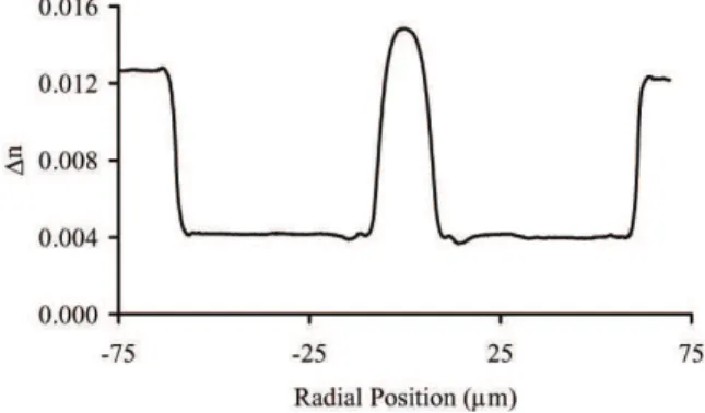
A commercial refractive index (RI) profiler was employed to measure the RI difference (∆n) in the produced fibre (Fig 2). Knowing the correspondence between index increase and oxide concentration in silica glass, the resulting ∆n was used to infer the final incorporated Al2O3 and P2O5 concentrations within the
fibre. Note that the index increase due to Er3+ was neglected due to its relatively low concentration and minor impact in raising the final RI profile around the Al doped region. The Al2O3 and P2O5 concentrations were estimated to be 8.0 mol%
and 0.3 mol% respectively. Information about the Er3+ ion concentration was deduced from the 1.5 µm absorption spectra (Fig 3) and in conjunction with the absorption cross section coefficients reported in Ref 2. Considering an attenuation coefficient of 230 dB/m and an absorption cross-section at 1.53 µm of 5×10-25 m2, the Er3+ ion concentration in the fibre was estimated about 2500 ppm mol Er2O3.
Figure 2. Refractive index difference of Er3+
doped fibre
Additional information regarding the relative Er3+ ion distribution in this fibre was obtained from the investigation of this fibre with the aid of a fluorescence intensity based confocal optical microscopy technique [6]. Two dimensional cross section images (Fig 4) as well as transverse linescans (Fig 5) displaying the relative ion distribution for all elements present in the produced fibre were also obtained from the application of a Nano-secondary ion mass spectroscopy (Nano-SIMS) scheme [7].
IV. RESULTS AND DISCUSSION
As evident from the set of data obtained as part of the characterisation process (Figs 2, 4, 5), this fibre exhibits a uniform elemental distribution in the central core region. In contrast to the conceptualised fibre design, the produced fibre appears to have a homogeneous RI profile with no signs of the interleaved silica regions that were deposited in order to form the two distinct Er3+ containing rings of Fig 1.
Figure 3. Spectral attenuation of Er3+
doped fibre
We believe that this attribute is due to the highly mobile nature of Al in silica, which continued to diffuse within the host glass matrix even after the sintering phase and the subsequent incorporation of the extra silica layers. In a recently published report, Tang et al studied the Al incorporation in sintered glass layers and collapsed preforms during a multiple-solution doping technique in optical fibre fabrication [8, 9]. By measuring and comparing the peak Al content in the fabricated preform cores after sintering and then after the collapse stage, it was found that the peak Al-content in the preform core was on average about 15% less than for the sintered glass layer before preform collapse. They proposed that Al was redistributed during the collapse phase, since calculations showed that the overall Al-content in the preform core was only slightly less than in the overall volume of the sintered layer, indicating that Al was redistributed outwards from the centre of the core. Although the precise mechanisms for why is this happens are uncertain, a similar redistribution of the Al must have taken place during the fabrication of this fibre too. It is quite clear from the distribution profile that Al is redistributed not only outwards from the core centre (i.e., towards the P containing ring), but also inwards, indicating that Al mobility is encouraged during the high temperatures of the extra silica layers deposition and the preform collapse. This is in agreement with previous reported data showing that alumina particles up to 80 µm in size can be dissolved completely in SiO2 within 100 s at 1855 °C [10].
More importantly, it can be observed that the RE ions have also diffused in a similar manner to that of Al. This observation is in agreement with past studies on RE doped silica fibres, where it has been empirically established that Al co-doping can be used for controlling the radial profiles of REs1. As a result, it becomes evident that the proposed fibre fabrication method promotes the redistribution of the Er3+ ions along the central core region. The latter is known to be integral for the successful operation of lasing and amplifying fibre devices.
Another clear benefit from the application of this fibre fabrication approach is related to the production of large mode area fibres. Manufacture of such fibres requires deposition of many supplementary doped layers fabricated with the repeat of the solution doping and sintering stages. This recurring process frequently leads to the formation of undesirable artefacts such as bubbles.
Figure 4. Cross section images of the relative elemental distribution obtained with the application of the NanoSIMS technique7. (a) Al, (b) P and (c) Er.
With the technique proposed here, it is only necessary to create one additional dopant layer. Furthermore, high elemental concentration could be achieved with the implementation of the multiple solution doping technique [8, 9]. Careful pre-selection of the number of additional silica layers to be deposited after the solution soaking and sintering stages can allow further control on the final core to cladding ratio.
Figure 5. Transverse profile through the centre of the fibre showing the relative Al (continuous line), P (dashed line) and Er (dotted line) ion
distributions. Also shown is the RI difference (dashed-dotted line)
V. CONCLCUSIONS
A new fibre fabrication approach as part of the MCVD and solution doping techniques was presented. It was shown that the deposition of additional silica layers subsequent to the solution doping and sintering stages can improve the incorporation of Al and subsequently that of the Er3+ ions.
ACKNOWLEDGMENT
M. Ude and S. Trzesien from LPMC are greatly acknowledged for the preform and fibre fabrication.
REFERENCES
[1] M.J.F.Digonnet, Rare-earth-doped fiber lasers and amplifiers, 2nd ed., New York: Dekker, 2001.
[2] A. Mendez and T. F Morse, Specialty optical fibres handbook, Amsterdam: Academic Press, 2006, pp 195-242.
[3] J. B. MacChesney, P. B. O’Connor, F. V. DiMarcello, J. R. Simpson, and P. D. Lazay, “Preparation of low loss optical fibers using simultaneous vapor phase deposition and fusion,” International Congress of Glass, 6:40–44, 1974.
[4] J. E. Townsend, S. B Poole, and D. N. Payne, “Solution doping technique for fabrication of rare earth doped optical fibers,” Electron. Lett., vol. 23, pp.329–331, March 1987.
[5] F. Sidiroglou, Micro-characterisation of RE doped optical fibres, PhD Thesis, Melbourne University , 2007.
[6] F. Sidiroglou, S. Huntington, A. Roberts, and G. Baxter , “Micro-characterisation of erbium-doped fibers using a Raman confocal microscope,” Opt. Express, vol 13, pp. 5506-5512, July 2005. [7] F. Sidiroglou, S. T. Huntington, A. Roberts, R. Stern, I. R. Fletcher, and
G. W. Baxter , “Simultaneous multidopant investigation of rare-earth-doped optical fibers by an ion microprobe,” Opt. Lett., vol. 31, pp. 3258-3260, October 2006.
[8] F. Z. Tang, P. McNamara, G. W. Barton and S. Ringer, “Multiple solution-doping in optical fibre fabrication I – Aluminium doping,” Journal of Non-Crystalline Solids, vol. 354, pp. 927-937, February 2008 [9] F. Z. Tang, P. McNamara, G. W. Barton and S. Ringer, “Multiple solution-doping in optical fibre fabrication: II - Rare earth and aluminium co-doping,” Journal of Non-Crystalline Solids, vol. 354, pp. 1582-1590, March 2008
[10] S.H. Risbud, V.F. Draper, J.A. Pask, “Dependence of Phase Composition on Nuclei Available in SiO2-A12O3 Mixtures,”J. Am.
Ceram. Soc., vol. 61, pp. 471-472, September 1978.