READ THESE TERMS AND CONDITIONS CAREFULLY BEFORE USING THIS WEBSITE. https://nrc-publications.canada.ca/eng/copyright
Vous avez des questions? Nous pouvons vous aider. Pour communiquer directement avec un auteur, consultez la première page de la revue dans laquelle son article a été publié afin de trouver ses coordonnées. Si vous n’arrivez pas à les repérer, communiquez avec nous à [email protected].
Questions? Contact the NRC Publications Archive team at
[email protected]. If you wish to email the authors directly, please see the first page of the publication for their contact information.
NRC Publications Archive
Archives des publications du CNRC
This publication could be one of several versions: author’s original, accepted manuscript or the publisher’s version. / La version de cette publication peut être l’une des suivantes : la version prépublication de l’auteur, la version acceptée du manuscrit ou la version de l’éditeur.
Access and use of this website and the material on it are subject to the Terms and Conditions set forth at
Hand Tracking for Interactive Pattern-Based Augmented Reality
Malik, S.; McDonald, C.; Roth, Gerhard
https://publications-cnrc.canada.ca/fra/droits
L’accès à ce site Web et l’utilisation de son contenu sont assujettis aux conditions présentées dans le site
LISEZ CES CONDITIONS ATTENTIVEMENT AVANT D’UTILISER CE SITE WEB.
NRC Publications Record / Notice d'Archives des publications de CNRC:
https://nrc-publications.canada.ca/eng/view/object/?id=c8cd1d7f-971f-4237-bca7-f60b8bd22252 https://publications-cnrc.canada.ca/fra/voir/objet/?id=c8cd1d7f-971f-4237-bca7-f60b8bd22252
National Research Council Canada Institute for Information Technology Conseil national de recherches Canada Institut de technologie de l'information
Hand Tracking for Interactive Pattern-Based
Augmented Reality *
Malik, S., McDonald, C., Roth, G.
October 2002
* published in IEEE and ACM International Symposium on Mixed and Augmented Reality 2002, pp. 399-406. Darmstardt, Germany. October 2002. NRC 45858.
Copyright 2002 by
National Research Council of Canada
Permission is granted to quote short excerpts and to reproduce figures and tables from this report, provided that the source of such material is fully acknowledged.
Hand Tracking for Interactive Pattern-based Augmented Reality
Shahzad Malik
Dept. of Computer Science
University of Toronto
Toronto, ON, Canada
[email protected]
Chris McDonald
School of Computer Science
Carleton University
Ottawa, ON, Canada
[email protected]
Gerhard Roth
Computational Video Group
National Research Council
Ottawa, ON, Canada
[email protected]
http://www.cv.iit.nrc.ca/research/ar
Abstract
Pattern-based augmented reality systems are considered the most promising approach for accurately registering virtual objects with real-time video feeds. The problem with existing solutions is the lack of robustness to partial occlusions of the pattern, which is important when attempt-ing natural interactions with the virtual objects.
This paper describes a fast and accurate vision-based pat-tern tracking system that allows for autocalibrated 3D augmentations of virtual objects onto known planar pat-terns. The tracking system is shown to be robust to changes in pattern scale, orientation, and most importantly partial occlusions. A method to detect a hand over top of the pattern is then described, along with a method to ren-der the hand on top of the virtual objects.
1. Introduction
Unlike virtual reality, which encompasses a user in a completely computer-generated environment, augmented reality (AR) is a technology that attempts to enhance a user’s view of the real environment by adding virtual ob-jects, such as text, 2D images, or 3D models, to the display in a realistic manner.
Clearly, the realism that a user will experience in an augmented reality environment is directly related to the stability of the registration between the virtual and real-world objects. Additionally, the method in which the user will interact with the virtual objects should be natural and intuitive; otherwise the effectiveness of the augmentations will be lost.
One of the most promising vision-based augmented re-ality techniques involves tracking a planar pattern in real-time and then augmenting virtual objects on top of the pat-tern based on its pose. In [9, 10], black and white planar patterns are tracked resulting in relatively stable registra-tions, but the tracking algorithms fail to provide any robust-ness to partial pattern occlusions. Specially arranged col-ored blobs are tracked in [11] that can handle partial
occlu-sions for a brief period of time via Kalman filtering, but the blob centroids are less reliable at different scales or plane orientations. Other techniques address robustness and oc-clusion, but only in hybrid configurations involving expen-sive magnetic or inertial trackers and stereo configurations [12, 13, 14].
Hand gesture recognition is considered one of the most natural methods to interact in an augmented reality envi-ronment, so it is not surprising that researchers have been experimenting with this mode of user input. A finger track-ing system for an augmented chess game is described in [1], but the use of a special glove with retroreflective markers is somewhat cumbersome. A correlation-based technique that doesn’t require any special markers to track the fingertip is described in [8], but the system assumes that lighting and orientation are relatively fixed and controlled. The Visual Panel system as described in [2] is most similar to our ap-proach, but the hand tracking system is only described in the context of a user-interface and not in terms of an aug-mented reality system. As a result, the Visual Panel system assumes that all four sides of the pattern will be partially visible, which inhibits the mobility of a user wearing a head-mounted, video see-through display.
In this paper we describe the implementation of a plane-based augmented reality system that tracks planar patterns in real-time, onto which virtual 2D and 3D objects can be augmented. Interaction with the virtual objects is possible via a hand detection system that can generate user-interface events. In comparison to the Visual Panel approach, our system allows the pattern to be significantly occluded or hidden, allowing a user much more interaction freedom while in motion. Additionally, a method to prevent the vir-tual augmentations from visually occluding a user’s hand is described
2. Planar homographies
For pattern-based augmented reality, a planar pattern defines a world coordinate system into which virtual objects will be placed, as depicted in Figure 1. It would be
conven-ient if the planar pattern itself could be used to determine a camera projection matrix that could be directly applied to the coordinates of a virtual object for augmentation pur-poses. This would eliminate the need for a separate calibration procedure, thus simplifying the system for the end-user.
Figure 1 – Coordinate space defined by a planar pattern
If we assume that the planar pattern defines the Z=0 plane in world space, we note the following simplification when projecting a point (xw, yw, zw) on the planar pattern into a point (xs, ys) in image space
= = = 1 1 1 0 34 32 31 24 22 21 14 12 11 34 33 32 31 24 23 22 21 14 13 12 11 w w w w w w s s s y x H y x p p p p p p p p p y x p p p p p p p p p p p p w y x
where pij defines the i,j-th element of the standard 3x4 per-spective projection matrix, and H is a 3x3 2D-to-2D projec-tive transformation known as a homography [3].
Every correspondence between a point in pattern and image space gives the following two linear equations
13 12 11 33 32 31
)
(
h
x
h
y
h
h
x
h
y
h
x
s w+
w+
=
w+
w+
23 22 21 33 32 31)
(
h
x
h
y
h
h
x
h
y
h
y
s w+
w+
=
w+
w+
where hij represents the i,j-th element of H. In matrix form we have 0 h= − − − − − − s w s w s w w s w s w s w w y y y x y y x x y x x x y x 1 0 0 0 0 0 0 1 where h = [h11 h12 h13 h21 h22 h23 h31 h32 h33]T is a 9-element
vector containing the elements of H. Therefore, with at least n ≥ 4 non-collinear point correspondences between world (pattern) space and image space, we repeat the above equation n times to solve for all the elements of h using singular value decomposition [4].
2.1. Camera calibration via homographies
Unfortunately, H alone cannot be directly used to aug-ment virtual 3D objects into the image, since the Z compo-nent from pattern space is assumed to always be zero.
Since H is a simplification of the general perspective projection matrix described earlier (where Z=0), it can be defined as
=
3 32 31 2 22 21 1 12 11t
r
r
t
f
r
f
r
f
t
f
r
f
r
f
H
v v v u u uwhere fu and fv are the focal lengths with aspect ratio taken into account, rij is the i,j-th element of a rotation matrix R, and T=(t1, t2, t3) defines a translation vector. Both R and T are used to align the world and camera coordinate spaces. Based on this simplification, recent work in camera calibra-tion [5, 6, 7] involving planar homographies show that the intrinsic and extrinsic camera parameters can be recovered from H. Therefore the focal length, the aspect ratio, and the elements of R and T can be recovered and used for the aug-mentation of virtual 3D objects.
3. System outline
In our augmentation system, known 2D black and white planar patterns (as depicted in Figure 2) are detected in a live video stream, and predetermined corner features inside of the pattern are tracked in real-time. Patterns con-sist of a thick black border, inside of which a number of white rectangles are distributed. The corners of the white rectangles are stored in a data file that is associated with the pattern upon system startup. Although no strict arrange-ment or number of rectangles is enforced, it is important to generate patterns that are uniquely identifiable with respect to other existing patterns, as well as under 90 degree rota-tions. Additionally, each rectangle should be placed far enough from other rectangles so that the corner features will be easy to distinguish. Black and white patterns are pre-ferred over color ones due to their high contrast.
Figure 2 – Examples of black and white patterns
A homography between the original pattern and the current pattern in image space is computed. It is then used to extract camera parameters and perform autocalibrated augmentations of virtual 2D and 3D objects onto the pat-tern. The homography can also be used to detect and track a user’s hand over top of the pattern, which is useful for intuitive interactions with virtual objects. The entire system is outlined in Figure 3.
Image coordinates
World (pattern) coordinates
Figure 3 – High-level system outline of the pattern and hand tracking system
4. Robust pattern tracking
The following sections cover the 2D pattern tracker in more detail. There are two modes of operation for the tracker, Detection Mode and Tracking Mode, which are depicted in Figure 4.
Figure 4 – Outline of the tracking system
4.1. Detection mode
Before known individual corner features can be tracked from frame to frame, the system must first uniquely identify any valid pattern(s) within the video frame. This is known as Detection Mode, and is the initial state of the augmenta-tion system. Using a method similar to [9], the search pro-ceeds as follows:
Threshold the frame into a binary image. Dynamic thresholding provides the best results, but static thresh-old values are also sufficient in known environments. Find connected regions of black pixels and only accept
regions whose bounding boxes meet size and aspect ra-tio thresholds of our known black-bordered patterns (in order to reject invalid regions).
Find the four strongest black corner pixels of the con-nected region and generate a polygon consisting of these vertices in clockwise order.
Compute a homography from the known boundaries of the original pattern to the polygon corners.
Using this homography, create a new image consisting of unwarped pixels from the video frame.
Find the best matching pattern by comparing the un-warped image with images of the known patterns (via simple binary image subtraction).
Figure 5 shows an example of unwarping the pixels within a connected region, and finding the best matching original pattern. Note that four homographies must be computed for each region, followed by four image comparisons, since there are four potential orientations of the original pattern. As mentioned earlier, the orientation of the original pattern should be unambiguous when viewed at 90, 180, and 270 degrees.
Figure 5 – Example of unwarping a region
4.2. Tracking mode
The previous section outlined a fast approach to self-identifying known planar patterns in a frame of video. Ex-isting methods proposed in [9, 10] consider this to be suffi-cient in order to begin augmenting virtual objects onto the pattern. The advantage of this approach is the simplicity of the system. However, as soon as any portion of the planar region is occluded (by the extents of the screen or by a foreground object, for example), the detection process completely fails. For interactive augmented reality this is unacceptable, since we want to manipulate virtual objects in the augmentation using hand gestures.
This section proposes an efficient corner tracking algo-rithm which allows continued pattern tracking in the pres-ence of significant occlusion. The basic idea involves tracking the known corner features for a detected pattern from frame to frame, and robustly computing the homogra-phy for the planar pattern based on these interior corner features, instead of simply relying on the four outside cor-ners of the black pattern border. Additionally, since local features are tracked from frame-to-frame, an increase in performance can be expected.
4.2.1. Search window computation. The first stage of
Tracking Mode consists of computing a local search
win-dow Wi for each corner xi, inside of which we expect to find
win-dow is found by placing a small rectangular region around the original corner feature in pattern space and then trans-forming it into the current frame using the homography computed in the previous frame. If the system was previ-ously in Detection Mode, this homography is the one used to normalize the planar region. Our current system uses patterns that are 64x64 pixels, and the search regions for each corner are 9x9 pixels (in pattern space). The size of the search region determines how much pattern motion the tracking system can tolerate in screen space. Increasing the search region size would allow for more motion, but this also increases the possibility of ambiguous corner detec-tions when the search window overlaps multiple valid cor-ners.
4.2.2. Corner detection. To find the actual corner
loca-tions, we do the following for each search window Wi: Apply a Harris corner finder [15] with subpixel
accu-racy on each pixel in Wi. Since the search window is an arbitrary four-sided polygon, it must be scan-converted using computer graphics techniques.
Extract the strongest corner within Wi to determine the actual corner position that corresponds to the original corner from the pattern. If no corner is detected, mark the corner’s tracking status as having failed for this frame.
4.2.3. Homography updating. Using the set of subpixel
corner locations found in the current frame, a new set of corner correspondences, {x ↔ x΄}, from the original pattern into image space is computed. Using the well-known RANSAC approach as outlined in [3], a new homography is determined as follows:
Randomly sample four non-collinear x ↔ x΄
corre-spondences.
Compute H from the random sample.
For all correspondences, compute the distance between
x΄ and Hx.
Count the number of pairs for which the distance is below some threshold. A value between 2.0 and 4.0 works well for our system. These correspondences are considered our inliers, and the rest are labeled as out-liers.
Store the H that has the highest number of inliers IH. Refit the homography H using these inliers.
The motivation behind random sampling is to remove inac-curate or mismatched corner locations from the homogra-phy computation. This allows the homograhomogra-phy to be robust to partially occluded features, which is important for subse-quent corner predictions and stable augmentations.
The number of random samples is capped at the maxi-mum number of known corners Imax for the detected pattern. Most of our patterns consist of four to eight white rectan-gles, resulting in 16 to 32 corners. In order to reduce the
number of samples further, random sampling stops if the highest number of inliers IH is above the following thresh-old
max Q
H
T
I
I
≥
where TQ defines a quality measure between 0 (low) and 1 (high). A value above 0.75 provides relatively stable ho-mographies.
The best homography computed after random sampling is then used as the corner predictor in the next frame. Note that random sampling can fail under the following in-stances:
There are less than 4 non-collinear x ↔ x΄
correspon-dences.
The best computed H fails to meet our TQ criterion IH falls below 4, which is the minimum number of
cor-respondences required for computing H in the next frame.
In such cases, the tracking system reports tracker failure and reverts back to Detection Mode.
The basic idea behind updating the homography via random sampling is to increase the robustness of the pattern tracker. With multiple corners being tracked simultane-ously, occlusions of a subset of the feature points should have little or no effect on the corner prediction in the next frame. For example, if a detected pattern consisting of 24 corners is being tracked, the homography should still be able to predict corner positions for the next frame even if approximately 16 corners are currently occluded by a user’s hand. The assumption is that the other 8 corners inter-spersed around the pattern area are sufficient to accurately determine the pattern’s current orientation. In fact, 4 unoc-cluded, non-collinear corners are all that is necessary. The predicted locations for the occluded corners will still be searched in upcoming frames so as soon as the occlusion stops (i.e. the user’s hand is removed from the pattern) all 24 corners will be detected again.
5. Hand detection
5.1. Image subtraction using the homography
5.1.1. Image subtraction. Image subtraction is a
com-monly used technique for detecting changes in a video scene between frames or with respect to a common refer-ence frame. This approach relies on a fixed camera posi-tion relative to the reference scene in order to detect the pixel variation due to foreground changes. This restriction often eliminates image subtraction as a useful tool in a vi-sion-based AR system, due to the potential freedom of the camera motion.
With our system, we note that the pattern space repre-sentation of each frame has a fixed position and orientation regardless of camera or target motion. This is due to the
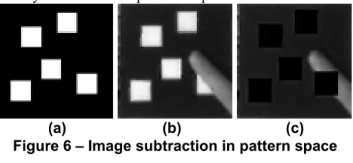
pattern-to-frame space homography being computed for each frame. When the frame is warped using the inverse homography (as in Figure 5), the position and orientation of the camera and target are lost. We can exploit this fact as we did for pattern detection in order to initialize pattern-space image subtraction. Figure 6 shows the three images used by the subtraction phase of a particular video frame.
(a) (b) (c) Figure 6 – Image subtraction in pattern space
Figure 6a shows the original pattern (reference), whereas Figure 6b shows the pattern-space representation of the current frame warped using the inverse homography. Figure 6c (the destination image d) is the result of subtrac-tion using the following equasubtrac-tion relating pixels of the cur-rent (c) image and reference (r) image to the destination (d) image:
pixel
d=
pixel
c−
pixel
r (1) with the constraint that0
)
0
(
pixel
d<
pixel
d=
if
The subtraction equation (1) exploits the fact that the pattern has only black and white pixels. The intensity of the white regions of the target can be greatly influenced by lighting conditions and shadows (under significant target and camera motion) which make them difficult to distin-guish from the hand regions. For this reason, the white regions are ignored in favor of those that differ significantly from the black pattern space. Image thresholding is applied to the destination image in order to separate the occluding regions from the pattern.
5.1.2. Image thresholding. Another benefit to this
subtrac-tion heuristic is its simplificasubtrac-tion of the thresholding proc-ess. The subtraction leaves a destination image that con-tains only hand pixel intensity and near-black pixel inten-sity, as shown in Figure 7b. Figure 7a shows the target be-ing partially occluded by a hand region and Figure 7b shows the pattern-space representation after image subtrac-tion.
(a) (b)
Figure 7 – Histogram source for thresholding
The threshold value is determined by analyzing the his-togram of the pattern-space destination image. The histo-gram shown in Figure 8 is capturing the intensity frequen-cies of the image shown in Figure 7b.
Figure 8 – Histogram of subtracted image
The two distinct peaks in the histogram represent the black region (left) and hand region (right). The threshold value is chosen to be the local minimum between these two maximums. After the thresholding is applied, the range and average intensity of the hand is found by accumulating pix-els in the video frame that correspond to white pixpix-els in the destination image after thresholding. With this colour in-formation, a flood-fill algorithm is applied to find the hand regions. Figure 9 shows the binary representation of the hand colored pixels that were visited during the flood-fill algorithm. All large blobs of connected hand pixels are stored in the form of pixel sets which are used as a repre-sentation of the hand in the AR system.
Figure 9 – Binary image of hand color locations
5.1.3. Finger detection via blob finding. The fingers of
the hand are detected by scanning the binary image for pix-els of full intensity. Each time such a pixel is found a sub-routine is called to perform a neighborhood flood-fill opera-tion to collect all neighboring pixels. This routine is stack-based, where found pixels are pushed onto a stack until such time as their neighbors can be examined. At that point, all favored neighbors are then pushed onto the stack and the process continues. To avoid re-visiting a candidate pixel, an image-sized integer array is maintained to record visited pixel locations. A blob has been defined when its corresponding pixel stack is empty. When this occurs, the blob can be examined to rule out obvious non-finger pixel sets. In our current implementation, a minimum pixel count of 60 is used to eliminate small blob regions caused by camera noise (assuming pattern space is 64x64 pixels).
Figure 10 – Binary image of finger blob location
Figure 10 shows the result of running the blob detection algorithm on the binary image shown in Figure 9. With this step, the hand pixel set has been captured (a single finger blob in this case).
5.2. Improving the augmentation
With this hand detection mechanism in place, im-provements to the visual and functional aspects of the aug-mentation system can be made.
5.2.1. Visual correction using the stencil buffer. The
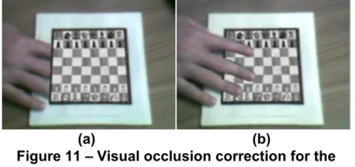
standard procedure used by this system to augment a video sequence with virtual objects in real-time is to render the virtual objects over each captured frame (ignoring the true occlusion relationship between real and virtual objects). As a result, the hand is part of the captured frame and it thus becomes occluded by any virtual objects that are rendered on top (as shown in Figure 11a). The immersive illusion that is created when augmenting a video scene is dimin-ished when obvious occlusion inaccuracies exist.
Using the point-set representation of the hand, the con-vex hull of each blob set is computed in order to have a clockwise contour of each hand component. This represen-tation of the hand lends itself to the standard polygon draw-ing facilities of OpenGL. Durdraw-ing a render cycle each poly-gon, defined by the convex hull of a hand region, is dered to the stencil buffer. When the virtual object is ren-dered, a stencil test is performed to omit pixels that overlap the polygons in the stencil buffer. This facility produces augmentations as shown in Figure 11b. As the camera or target position change, the hand regions that occlude the pattern are robustly detected.
(a) (b)
Figure 11 – Visual occlusion correction for the hand using the stencil buffer
It is worth pointing out that the occlusion relationship is only visually correct for augmentations located on the pattern plane (Z=0). For augmentations of 3D objects that rise up from the surface of the pattern, the hand pixels will (incorrectly) be rendered over top of the virtual object as well since we do not know how far above the pattern the hand actually is. However, for interaction purposes, it is desirable to have the hand visible over top of the augmenta-tions rather than being completely occluded.
5.2.2. Search box invalidation. Another aspect of the
augmentation system that can be improved with this occlu-sion information is the corner tracking integrity. When the hand occludes a corner’s search box, the result from the corner finder can be inaccurate due to the hand or hand shadow intensity. A quick collision scan can be performed to test the containment of any hand pixels in the search boxes. This test can immediately invalidate any search boxes that contain hand pixels so those corners will be ig-nored during the tracking phase.
Figure 12 shows valid search boxes (yellow) and those that are invalidated due to hand occlusion (red). This in-validation process significantly improves the overall stabil-ity of the augmentation when occlusion is occurring.
Figure 12 – Search box invalidation
6. Hand gesture recognition
The goal for interaction in this implementation was the abil-ity to recognize point and select gestures on the two-dimensional plane defined by the target. The information gathered by the hand detection phase simplifies the recogni-tion process for simple gestures. The fingertip locarecogni-tion is calculated to simulate the pointing action, and the finger blob count is used for the select action.
6.1. Fingertip location
To determine the location of the user’s point and select ac-tions a pointer location must be computed from the hand point set. To simplify the process, a number of assumptions were made. The first assumption deals with the amount of target occlusion. The tracking system requires that ap-proximately half of the target corners be visible. Given the
size of the physical target, only a small portion of a hand can occlude the target at any given time during tracking. Therefore it is reasonable that only fingers shall occlude the target. From this we get:
Assumption 1: Separated fingers will be detected as
sepa-rate blobs in the detection phase.
Due to the simplicity of the desired interaction, a fur-ther assumption was made:
Assumption 2: Fingers will remain extended and relatively
parallel to each other.
Pointing with one or more extended fingers is a natural human gesture, so this is a reasonable assumption. The third constraint used to simplify the process is the following obvious fact:
Assumption 3: Any hand pixel set will contain at least one
pixel on the border of the pattern-space representation of the current frame.
By making use of these assumptions the process begins by selecting the largest detected finger blob. The blob used for illustration purposes is shown as a contour in Figure 13, and is the same finger blob shown in Figure 10. Using the blob’s point set, the orientation of the principal axis (the line cutting the finger blob in Figure 13) can be calculated using the central moments of the blob. The axis line is then defined by forcing it through the blob centroid. The next step involves finding the root point on the principal axis, which represents an approximation of where the finger joins the hand. This is possible because of Assumption 2. Using Assumption 3, a border pixel, rb, is chosen from the blob
and its closest principal axis point, rp, is chosen as the root.
The fingertip (tb) is the farthest point in the blob from the
root point, and is used as the pointer location.
Figure 13 – Fingertip location using orientation
6.2. Simple gesture capture
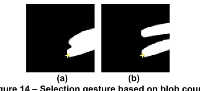
The basis of the mechanism to capture the gesture of selec-tion is the number of detected finger blobs, which is justi-fied by Assumption 1 of Section 6.1. A single detected finger blob represents the gesture of pointing, whereas mul-tiple detected finger blobs represent the gesture of selecting. This interaction can be performed, for example, by showing one finger for pointing and introducing a second finger over the target for selecting. Figure 14a shows a binary
repre-sentation of an alternative example of a point gesture and Figure 14b shows the select gesture, with the crosshair de-noting the corresponding pointer location.
(a) (b)
Figure 14 – Selection gesture based on blob count
At all times, the fingertip (selector) location is determined based on the largest detected blob. In Figure 14a, the larg-est blob is the combination of the index and middle finger. The fingertip position would be chosen at the tip of the middle finger due to its length dominance relative to the root point. In Figure 14b the largest blob is the middle fin-ger blob, which results in a similar position for the pointer. With this pointing and selection mechanism based on the fingers of the hand it is possible to interact with augmented virtual objects.
7. Results
7.1. Performance
One of the major design goals of our augmented reality system is real-time performance on standard PCs using off-the-shelf USB camera hardware. The current implementa-tion of our tracking system uses OpenGL to augment simple 2D textures and 3D objects onto the planar patterns at 20Hz on an Intel Pentium 3 800MHz PC equipped with an ATI Rage 128 Video card and an Intel CS110 USB camera (capturing 320x240 images).
In order to obtain an accurate estimate of the Detection
Mode time, we modified the implementation to always
re-main in Detection Mode and to use the computed homogra-phy to perform augmentation.
The current breakdown of average processing time per frame when viewing a static planar pattern consisting of 24 corners and a 2D augmentation is as follows:
Detection Mode: 29.1ms Tracking Mode: 10.7ms Hand Detection: 8.6ms Augmentation Time: 2.1ms
Clearly, the global search method is significantly slower than tracking 24 localized corner features. The sys-tem is usually in Tracking Mode, however, where the
per-formance is linearly proportional to the number of corners being tracked.
7.2. Scale invariance
One of the major advantages in using corners for track-ing is that corners are invariant to scale. The corner tracker can thus continue to track patterns at a large range of dis-tances from the camera. The use of a transformed search window for corner detection facilitates this process, since the search windows become smaller as the area occupied by the corner features in a particular pattern begins to shrink. Table 1 shows the range of scale allowed for the set of test patterns shown in Figure 15. Patterns differ in the number and/or arrangement of corner features. Scale is measured by computing the percentage of screen area covered by the bounding box around the tracked corners. Each pattern was first recognized in Detection Mode and then placed such that it covered approximately 50% of the view in a front-facing position. The pattern was then slowly moved away from the camera until tracking failure, after which the minimum percentage of occupied screen space during track-ing was computed. The process was repeated again for maximum scale by slowly moving the pattern closer to the camera instead of away from it.
Table 1 – Distance (scale) tracking tolerance for test patterns
Pattern Corners Min % of Screen Max % of Screen
Pattern A 7 1.4 102 Pattern B 17 1.3 190 Pattern C 20 1.6 257 Pattern D 20 1.6 236 Pattern E 22 1.3 275 Pattern F 24 1.2 218 Pattern G 40 1.5 370 A B C D E F G Figure 15 – Test patterns for tracking experiments
As Table 1 shows, all the patterns allowed tracking to continue when the pattern occupied less than 2% of the screen area. At such small scales, however, any significant movement of the pattern causes tracking failure since the corner search windows are extremely small. Experiments involving pattern movement at large distances showed that patterns occupying at least 10% still allow significant pat-tern movement. The number of corners in a patpat-tern does affect performance, as can be seen in Table 1. Pattern A, with only 7 corners, only allows the pattern to cover 102% of the screen area, while Pattern G, with 40 corners, allows
the pattern to cover 370% of the screen since more corners continue to be visible at this scale. When viewing a pattern close to the camera, extra corner features are beneficial since the majority of the pattern is outside the visible areas of the captured image. Increasing the number of corners does not appear to provide any significant improvement when viewing patterns far from the camera.
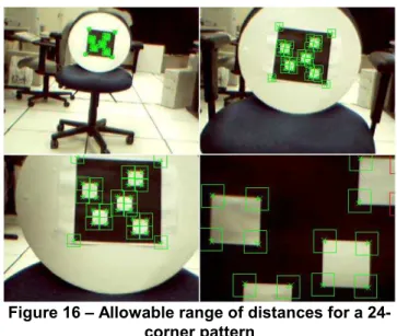
Currently, patterns must be visible in at least 25% of the view, with no occlusions, in order for Detection Mode to lock onto the pattern. This can be adjusted based on size and aspect ratio thresholds. Figure 16 shows the range of distances in which a front-facing pattern with 24 corners can be tracked successfully. Note the dynamically changing size of the search windows.
Figure 16 – Allowable range of distances for a 24-corner pattern
7.3. Orientation robustness
Due to perspective distortion, a square on the original pattern does not necessarily remain square when viewed at a sharp angle and projected into image space. Thus, cor-ners will change their shape which affects the corner finder’s detection ability. However, this is not a problem since the corner finder our system uses relies on finding intensity changes in two directions [15], which are still evi-dent even at severe orientations.
Figure 17 shows a 24-corner pattern undergoing a gradual rotation of 90 degrees. As can be seen, the corner detection begins to deteriorate when corners enter search boxes for other corners. However, as Figure 17 shows, the tracking continues up to almost 75-80 degrees, which is quite robust for many types of augmentations.
Figure 17 – Tracking under severe rotation
7.4. Occlusion robustness
One of the main advantages of our tracking approach is the ability to handle significant amounts of occlusion. Fig-ure 18 shows a 20-corner pattern experiencing approxi-mately 30% occlusion. The tracker can still detect enough corners so that a virtual 3D pyramid can be correctly aug-mented onto the plane.
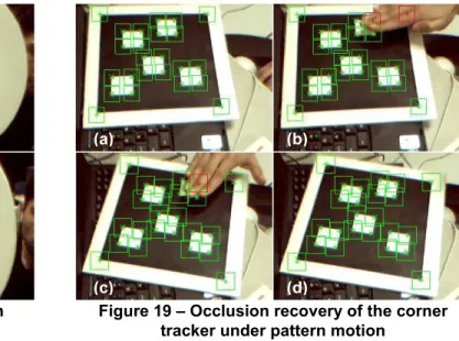
Even under motion, the prediction scheme allows cor-ners to be correctly recovered after temporary occlusions. Figure 19a shows a pattern with all of its 20 corners being tracked successfully (indicated by green corner search boxes). Figure 19b then shows a hand occluding two of the corners, with red boxes denoting the predicted locations. While occluded, the pattern is rotated slightly such that one of the occluded corners becomes visible again. The non-occluded corner is then recovered, as depicted in Figure 19c. Note that the other corner is still being occluded, but the predicted location has changed after rotation. After removing the hand from the scene, the predicted location allows the remaining corner to be recovered as well, as de-picted in Figure 19d.
Figure 18 – Occlusion robustness
Figure 19 – Occlusion recovery of the corner tracker under pattern motion
Occlusion robustness is directly related to the number of corner features available for tracking; the more corners a pattern has, the more tolerant it is of partial occlusions. In our experiments, Pattern G (with 40 corners) allows for the most occlusion. This was also evident in our scale experi-ments, since a larger number of corners allowed the patterns to be viewed at close range (when many corners were oc-cluded by the edges of the visible screen area).
It is worth mentioning that occlusion robustness cur-rently only occurs during Tracking Mode. In other words, if the corner tracker fails and the system reverts back to
Detection Mode, the pattern will only be detected
success-fully if it is completely visible and not occluded in any way.
7.5. Lighting robustness
Another favorable property of the corner feature for tracking purposes is its robustness to lighting. Since inten-sity changes in two directions form the basis of corner find-ing, no special considerations need to be taken into account from the tracker’s perspective in order to handle significant lighting changes or shadows. The corner tracker continues to compute an accurate homography, even under dramatic changes in lighting. This is important for robustness to hand shadows that occur when interacting with the aug-mented virtual objects.
8. Conclusion
In this paper we described a robust solution for vision-based augmented reality tracking that identifies and tracks, in real-time, known planar patterns consisting of a set of corners. The advantage of tracking corners is their robust-ness at a large range of distances, reliability under severe planar orientations, and tolerance of significant lighting
(a) (b)
changes or shadows. Due to their robustness to occlusion, a method to track a user’s hand in real-time was described which allows natural interactions with virtual objects on the pattern plane. Occlusion robustness is achieved by ran-domly sampling the set of corner correspondences, as well as by invalidating corner search regions that are determined to contain hand pixels.
Using the corner correspondences computed between the stored pattern and its projection in the image, it is pos-sible to compute a 2D homography H between the two. With this computed homography we can perform uncali-brated 2D augmentations by placing any 2D picture in place of the pattern in the image. Additionally, the homography can be computed even when some of the corners are oc-cluded.
From this computed homography it is possible to de-termine both the intrinsic and extrinsic parameters of the camera by an autocalibration process. This enables us to compute the full perspective camera projection matrix and to perform augmentations of not just 2D objects, but also of perspective-correct 3D objects. Therefore, the augmenta-tion system can automatically adjust to different types of cameras without having to go through a formal calibration step, as well as being able to handle zoom lenses.
The design of the system was described, and experi-ments demonstrated the feasibility and reliability of the system under various situations, most significantly under partial pattern occlusion. This robustness, combined with the unique approach of using a homography to continuously calibrate the camera as well as track a user’s hand, should bring augmented reality one step closer to becoming a mass-market technology.
9. References
[1] K. Dorfmuller-Ulhaas, D. Schmalstieg. “Finger Track-ing for Interaction in Augmented Environments”. Pro-ceedings of IEEE and ACM Symposium on Aug-mented Reality, 2001. pp. 55-64.
[2] Z. Zhang, Y. Wu, Y. Shan, and S. Shafer. “Visual Panel: Virtual Mouse, Keyboard and 3D Controller with an Ordinary Piece of Paper”. Proceedings of ACM Workshop on Perceptive User Interfaces (PUI) 2001.
[3] A. Zisserman, R. Hartley. Multiple View Geometry. Cambridge University Press, 2000.
[4] E. Trucco, A. Verri. Introductory Techniques for 3D
Computer Vision. Prentice-Hall, 1998.
[5] I. Shimizu, Z. Zhang, S. Akamatsu, K. Deguchi. “Head Pose Determination from One Image Using a Generic Model”. Proceedings IEEE Third International Con-ference on Automatic Face and Gesture Recognition, April 1998. pp. 100-105.
[6] Z. Zhang. “A Flexible New Technique for Camera Calibration”. IEEE Transactions on Pattern Analysis and Machine Intelligence. Vol. 22, No. 11, November 2000. pp. 1330-1334.
[7] P. Sturm. “Algorithms for Plane-based Pose Estima-tion”. Proceedings of IEEE International Conference on Computer Vision and Pattern Recognition (CVPR) 2000. pp. 706-711.
[8] J. Crowley, F. Berard, J. Coutaz. “Finger Tracking as an Input Device for Augmented Reality”. Proceedings of International Workshop on Automatic Face and Ges-ture Recognition, Zurich, 1995. pp. 195-200.
[9] J. Rekimoto. “Matrix: A Realtime Object Identifica-tion and RegistraIdentifica-tion Method for Augmented Reality”. Proceedings of 3rd Asia Pacific Computer Human In-teraction (APCHI) Conference, 1998. pp. 63-68. [10] H. Kato, M. Billinghurst. “Marker Tracking and HMD
Calibration for a Video-based Augmented Reality Conferencing System”. Proceedings of 2nd IEEE and ACM International Workshop on Augmented Reality (IWAR) 1999. pp. 85-94.
[11] J. Molineros, R. Sharma. “Real-Time Tracking of Multiple Objects Using Fiducials for Augmented Real-ity”. Real-Time Imaging 7, 2001. pp. 495-506. [12] T. Auer, A. Pinz. “The Integration of Optical and
Magnetic Tracking for Multi-User Augmented Real-ity”. Computer & Graphics 23, 1999. pp. 805-808. [13] R. Azuma, U. Neumann, S. You. “Hybrid Inertial and
Vision Tracking for Augmented Reality Registration”. Proceedings of IEEE Virtual Reality, 1999. pp. 260-267.
[14] A. State, G. Hirota, D. Chen, W. Garrett, M. Living-ston. “Superior Augmented Reality Registration by In-tegrating Landmark Tracking and Magnetic Tracking”. Proceedings of ACM SIGGRAPH 1996. pp. 429-438. [15] C. Harris, M. Stephens. “A Combined Corner and
Edge Detector”. Proceedings of 4th Alvey Vision Con-ference, 1988. pp. 147-151.