READ THESE TERMS AND CONDITIONS CAREFULLY BEFORE USING THIS WEBSITE.
https://nrc-publications.canada.ca/eng/copyright
Vous avez des questions? Nous pouvons vous aider. Pour communiquer directement avec un auteur, consultez la
première page de la revue dans laquelle son article a été publié afin de trouver ses coordonnées. Si vous n’arrivez pas à les repérer, communiquez avec nous à [email protected].
Questions? Contact the NRC Publications Archive team at
[email protected]. If you wish to email the authors directly, please see the first page of the publication for their contact information.
NRC Publications Archive
Archives des publications du CNRC
This publication could be one of several versions: author’s original, accepted manuscript or the publisher’s version. / La version de cette publication peut être l’une des suivantes : la version prépublication de l’auteur, la version acceptée du manuscrit ou la version de l’éditeur.
Access and use of this website and the material on it are subject to the Terms and Conditions set forth at Discrete element method for sand-structure interaction
Zeghal, M.; Edil, T. B.; Plesha, M. E.
https://publications-cnrc.canada.ca/fra/droits
L’accès à ce site Web et l’utilisation de son contenu sont assujettis aux conditions présentées dans le site
LISEZ CES CONDITIONS ATTENTIVEMENT AVANT D’UTILISER CE SITE WEB.
NRC Publications Record / Notice d'Archives des publications de CNRC: https://nrc-publications.canada.ca/eng/view/object/?id=9a67fc86-0f15-4fff-814e-e9d28c1fba39 https://publications-cnrc.canada.ca/fra/voir/objet/?id=9a67fc86-0f15-4fff-814e-e9d28c1fba39
Discrete element method for sand-structure interaction
Zeghal, M.; Edil, T.B.; Plesha, M.E.
NRCC-45680
A version of this document is published in / Une version de ce document se trouve dans :
3rd International Conference on Discrete Element Methods, Santa Fe, New Mexico, Sept. 23-25, 2002, pp. 317-322
1
DISCRETE ELEMENT METHOD FOR SAND-STRUCTURE INTERACTION
Morched Zeghal 1, Tuncer B. Edil 2, and Michael E. Plesha3 INTRODUCTION
Many experimental studies have been undertaken to investigate the mechanics of the interface between granular materials and structural surfaces. The direct shear and shaft pullout tests are the most common (Brummud and Leonards, 1973; ElSakhawy and Edil, 1996; Sengara, 1991). A variety of scales, configurations and boundary and loading conditions were used in these tests to capture the elements of the behavior. However, the majority of these investigations rely on measurements taken outside of the structure-medium interface to infer behavior at the interface. Effort has been made to correlate the macro-mechanical response of structure-medium systems to the microstructural characteristics of the interface. Uesugi and Kishida (1986) studied interface grain displacement using a reflex camera through a glass window of a simple shear device. Later, Boulon (1989), working with a modified plane direct shear test and using stereophotogrammetic analysis technique, was able to track the movement of particles. Obtaining microstructural information using laboratory testing techniques is an inherently difficult, tedious and time-consuming task. The use of the discrete element method (DEM) to study and delineate phenomena dictating the behavior of the interface provides a valuable alternative since it takes into account the discrete nature of materials and gives detailed information at the particle level where interface behavior occurs. This paper presents some parametric studies on the effect of modeling parameters on formation of shear zones in structure-medium interfaces.
DEM MODEL
The model used in this research is based on the early work of Cundall and Strack (1978, 1979) wherein a medium is modeled in two dimensions as an assembly of rigid circular discs, or elements. Each element is characterised by its radius, the position of its center and the rotation about its center. Contact between two elements is characterized by a point of contact and a direction that passes through the centers of the two elements. Relative displacements of elements result in a change of normal and tangential contact forces that are determined by the application of a linear elastic
1 Research Officer, National Research Council-Canada, Institute for Research in Construction Urban Infrastructure Rehabilitation Program, Building M-20, Ottawa, Ontario Canada K1A 0R6; phone: (613) 991-6273; email: [email protected]
2 Professor, Department of Civil & Environmental Engineering, University of Wisconsin-Madison, Madison, WI 53706; phone: (608) 262-3225; email: [email protected]
3 Professor , Department of Engineering Physics, University of Wisconsin-Madison, Madison, WI
force-displacement law at the contact. Further, the contact obeys an elastic perfectly plastic law (Coulomb’s friction law). Contact stiffnesses can be interpreted as penalty numbers that enforce the constraints of impenetrability and presiliding stick as they become larger. Newton’s law describes the motion of particles due to the forces acting on them.
SOIL-STRUCTURE SIMULATIONS: A PARAMETRIC STUDY
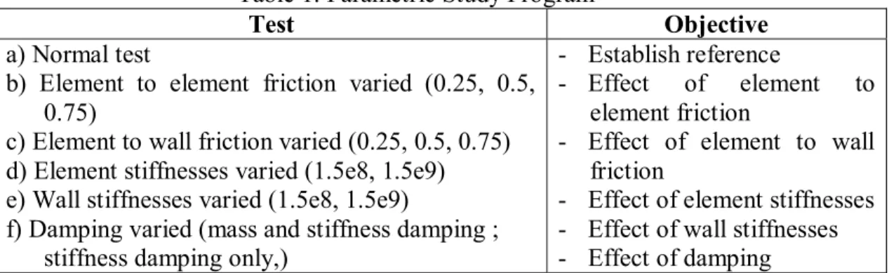
An assembly of 1000 particles was used. The boundaries of the assembly were rigid. The bottom surface is used to simulate a structure for which roughness was idealized by a saw tooth shape (Figure 4). The equilibrium state, resulting from compaction, was saved and served as the initial conditions for the parametric study. One parameter at a time was varied to determine the influence of that specific parameter on the behavior of the assembly. Table 1 summarises the simulations performed and their objectives.
Table 1. Parametric Study Program
Test Objective
a) Normal test
b) Element to element friction varied (0.25, 0.5, 0.75)
c) Element to wall friction varied (0.25, 0.5, 0.75) d) Element stiffnesses varied (1.5e8, 1.5e9) e) Wall stiffnesses varied (1.5e8, 1.5e9)
f) Damping varied (mass and stiffness damping ; stiffness damping only,)
- Establish reference
- Effect of element to
element friction
- Effect of element to wall friction
- Effect of element stiffnesses - Effect of wall stiffnesses - Effect of damping
Summary of Results
Based on the numerical simulations performed, it was concluded that the choice of parameters has almost no influence on the general trend of the results. More specifically:
• Element to element friction has a minor effect on the interface behavior. The normal force on the top wall increases with increasing friction.
• Boundary friction has almost no effect on the response.
• Element stiffnesses have no major changes in the outcome of the simulation. • Boundary stiffnesses: as expected, the normal force on the top boundary
increases when the boundary stiffnesses are raised, but no major changes, in the displacement or rotation fields at the contact, are detected.
• The shear band seems to spread a few particles from the rough boundary simulating the structure. In average, the interface thickness was about 5-8 particle diameters. This is in accordance with the value reported by Hoteit (1990) in his experimental measurements.
3
EFFECT OF STRUCTURE ROUGHNESS ON THE INTERFACE
In order to study the effect of structure roughness on the formation of a possible shear band, 1000 particles were used in the same set up as above. The assembly grain size distribution was the same. The slope of the saw teeth was used as a measure of the degree of the structure surface roughness, and four values were considered (2o, 10o, 20o, and 30o) but results for only two are reported below.
Low Roughness (2o Case)
This simulation was performed to replicate the case of a nearly smooth surface, and results are presented in Figures 1 through 3. The force network displays a more or less uniform force distribution through the sample. The displacement vectors suggest that the shear band is very narrow where the process zone is limited mainly to particles in immediate contact with the surface. Grain displacements and rotations are present primarily in a thin layer not exceeding 2 particle diameters in thickness. Furthermore, the slip zone is straight with no significant undulations.
Figure 1. Interparticle Forces for 2o Roughness
Figure 2. Displacement of Particles for 2o Roughness
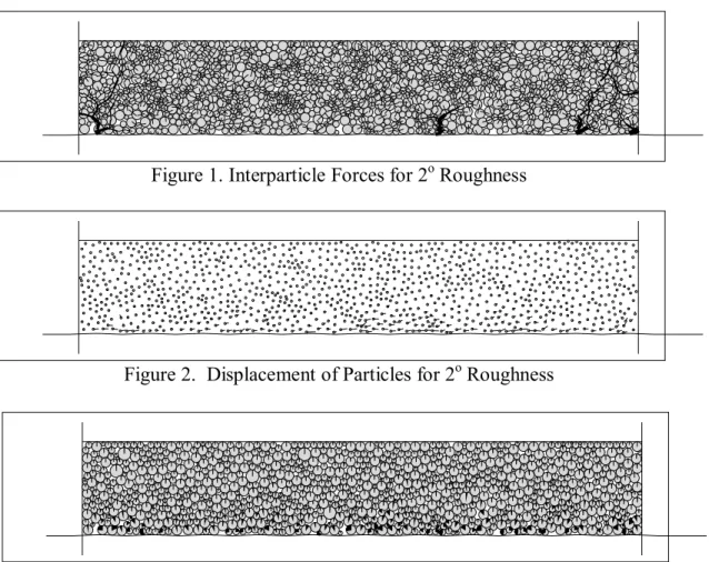
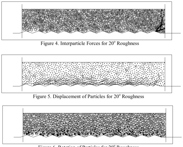
Rough Surface (20o Case)
Based on the results of the 2o and 10o cases, it was clear that the degree of roughness has an effect on the shear band formation, extent, and characteristics. It can be deduced from Figures 4 through 6, giving the results of the simulation done with the third level of roughness (20o slope), that the undulations in the shape of the shear zone become more important and more particles are involved in the shear process. The interface extends about 4 to 6 particle diameters from the structure.
Figure 4. Interparticle Forces for 20o Roughness
Figure 5. Displacement of Particles for 20o Roughness
Figure 6. Rotation of Particles for 20o Roughness
CONCLUSIONS
A parametric study showed qualitatively that element and element-to-boundary friction, element and element-to-boundary stiffnesses and damping, if not too heavy, have little or no effect on the behavior at the structure-medium. The investigation of surface roughness showed that the shear band is very thin in the case of very low degree of roughness which was used to model a relatively smooth surface. Furthermore, it appears that the shear zone thickness increases as the surface
5
roughness increases. The shear zone, in general, is a thin layer not exceeding 8 particle diameters. Further, the shape of the shear zone shows greater curvature and undulations with the increase in degree of structure surface roughness.
This information, at the microstructural level, was used to develop a new constitutive law for the interface that takes into account its microstructural features. The slip surface was idealized by a sinusoidal curve.
REFERENCES
Boulon, M. (1989). "Basic Features of Soil Structure Interface Behavior", Computer and Geotechnics, No. 7, pp 115-131.
Brummud, W. G. and Leonards, G. A. (1973). “Experimental Study of Static and Dynamic Friction between Sand and Typical construction Materials”, Journal of Testing and Evaluation, ASTM, No 12, Mar., pp. 162-165.
Cundall, P. A. and Strack, O. D. L. (1978). “The distinct Element Method as a Tool for Research in Granular Media”, Report to the National Science Foundation Concerning NSF Grant ENG76-20711, Part I.
Cundall, P. A. and Strack, O. D. L. (1979). “The distinct Element Method as a Tool for Research in Granular Media”, Report to the National Science Foundation Concerning NSF Grant ENG76-20711, Part II.
Cundall, P. A. and Strack, O. D. L. (1979). “A Discrete Numerical Model for Granular Assemblies”, Geotechnique, Vol. 29, No 1, pp 47-65.
ElSakhawy, N. R. and Edil T. B. (1996). "Behavior of Shaft-Sand Interface from Local Measurements", Transportation Research Record, No 1548, Washington, DC, pp. 74-80.
Hoteit, N. (1990). "Contribution à l’Étude du Comportement d'Interface Sable-Inclusion et Application au Frottement Apparent", Doctorate Thesis, Institut National Polytechnique de Grenoble, France.
Sengara, I. W. (1991). "Finite Element and Experimental Study of Soil-Structure Interfaces", Ph.D. thesis, University of Wisconsin-Madison, Department of Civil and Environmental Engineering.
Uesingu, M. and Kishida, H. (1986). “ Influential Factors of Friction between Steel and Dry Sands”, Soils and Foundations, Vol 26, No 2, pp. 33-46.