Publisher’s version / Version de l'éditeur:
Vous avez des questions? Nous pouvons vous aider. Pour communiquer directement avec un auteur, consultez la première page de la revue dans laquelle son article a été publié afin de trouver ses coordonnées. Si vous n’arrivez pas à les repérer, communiquez avec nous à [email protected].
Questions? Contact the NRC Publications Archive team at
[email protected]. If you wish to email the authors directly, please see the first page of the publication for their contact information.
https://publications-cnrc.canada.ca/fra/droits
L’accès à ce site Web et l’utilisation de son contenu sont assujettis aux conditions présentées dans le site LISEZ CES CONDITIONS ATTENTIVEMENT AVANT D’UTILISER CE SITE WEB.
Advances in Materials Science and Engineering, 2020, 2020-06-08
READ THESE TERMS AND CONDITIONS CAREFULLY BEFORE USING THIS WEBSITE. https://nrc-publications.canada.ca/eng/copyright
NRC Publications Archive Record / Notice des Archives des publications du CNRC :
https://nrc-publications.canada.ca/eng/view/object/?id=8faf6483-9a52-4562-bae7-15bd4c18ba92
https://publications-cnrc.canada.ca/fra/voir/objet/?id=8faf6483-9a52-4562-bae7-15bd4c18ba92
Archives des publications du CNRC
This publication could be one of several versions: author’s original, accepted manuscript or the publisher’s version. / La version de cette publication peut être l’une des suivantes : la version prépublication de l’auteur, la version acceptée du manuscrit ou la version de l’éditeur.
For the publisher’s version, please access the DOI link below./ Pour consulter la version de l’éditeur, utilisez le lien DOI ci-dessous.
https://doi.org/10.1155/2020/1902567
Access and use of this website and the material on it are subject to the Terms and Conditions set forth at
High frequency vibration fatigue behavior of Ti6Al4V fabricated by
wire-fed electron beam additive manufacturing technology
Wanjara, P.; Gholipour, J.; Watanabe, E.; Watanabe, K.; Sugino, T.; Patnaik,
P.; Sikan, F.; Brochu, M.
Research Article
High Frequency Vibration Fatigue Behavior of Ti6Al4V
Fabricated by Wire-Fed Electron Beam Additive
Manufacturing Technology
P. Wanjara ,
1J. Gholipour,
1E. Watanabe,
2K. Watanabe,
2T. Sugino,
2P. Patnaik,
1F. Sikan,
1,3and M. Brochu
31National Research Council Canada, Montreal, QC, Canada
2IHI Corporation, Yokohama-shi, Yokohama, Kanagawa, Japan
3McGill University, Montreal, QC, Canada
Correspondence should be addressed to P. Wanjara; [email protected] Received 13 March 2020; Accepted 27 April 2020; Published 8 June 2020
Academic Editor: Jose Cesar de Sa
Copyright © 2020 National Research Council of Canada. This is an open access article distributed under the Creative Commons Attribution License, which permits unrestricted use, distribution, and reproduction in any medium, provided the original work is properly cited.
Following foreign object damage (FOD), a decision to repair components using novel additive manufacturing (AM) technologies has good potential to enable cost-effective and efficient solutions for aircraft gas turbine engine maintenance. To implement any new technology in the gas turbine remanufacturing world, the performance of the repair must be developed and understood through careful consideration of the impact of service life-limiting factors on the structural integrity of the component. In modern gas turbine engines, high cycle fatigue (HCF) is one of the greatest causes of component failure. However, conventional uniaxial fatigue data is inadequate in representing the predominant HCF failure mode of gas turbine components that is caused by vibration. In this study, the vibratory fatigue behavior of Ti6Al4V deposited using wire-fed electron beam additive manufacturing (EBAM) was examined with the motivation of developing an advanced repair solution for fatigue critical cold-section parts, such as blades and vanes, in gas turbine engine applications. High cycle fatigue data, generated using a combination of step-testing procedure and vibration (resonance) fatigue testing, was analyzed through Dixon–Mood statistics to calculate the endurance limits and standard deviations of the EBAM and wrought Ti6Al4V materials. Also plots of stress (S) against the number of cycles to failure (N) were obtained for both materials. The average fatigue endurance limit of the EBAM Ti6Al4V was determined to be greater than the wrought counterpart. But the lower limit (95% reliability) of 426 MPa for the EBAM Ti6Al4V was lower than the value of 497 MPa determined for wrought Ti6Al4V and was attributed to the slightly higher data scatter–as reflected by the higher standard deviation–of the former material.
1. Introduction
In airfoil design for aeroengine gas turbines, soft- and hard-body impact is one of the greatest concerns for flight safety, especially during the takeoff and landing stages. For in-stance, in turbofan engines of most modern aircraft, the fan stage can generate up to 90% of the thrust. Foreign object impact on the leading edges of fan blades can trigger not only losses in thrust, but also changes in the vibration charac-teristics of the engine that can result in cumulative structural damage through fatigue at high cycles and stress levels [1–3].
To assure flight safety, the aviation industry has developed maintenance protocols to inspect, maintain, and refurbish/ replace blades having FOD. The refurbishing scheme de-pends on the severity of impact and can involve only blade blending for minor damage to complex repairs, using welding and machining operations, for moderate to severe damage [4]. A commonly applied repair scheme to refurbish extensively eroded first stage titanium alloy fan blades in-volves preparing a repair patch–by stamping, rolling, or forging–followed by welding and machining [5]. The recent developments in AM offer new repair opportunities to
Volume 2020, Article ID 1902567, 14 pages https://doi.org/10.1155/2020/1902567
restore FOD on metallic blades more cost-effectively through process automation, quicker cycle times, and re-ductions in high-value material waste [6–8]. A wide variety of AM platforms have been considered for repair based on DED technologies that involve melting of powder and/or wire feed using a laser or EB energy source so as to add material layer by layer to refurbish damaged parts [9]. Over the last 20 years, different DED technologies have been matured considerably for dimensional restoration, but fa-tigue critical repairs continue to remain at the development or qualifying level due mostly to the limited performance data and low confidence scatterplots [10]. Furthermore, to consider advanced repair with additive design for structural parts subjected to high frequency vibrations, such as the rotating gas turbine engine blades, conventional uniaxial fatigue data (from low to high cycle regimes) at a R > 0 are inadequate in representing HCF failures caused by blade resonance conditions [11, 12].
High-speed rotor blades in turbines and compressors experience different excitation sources and, of concern to aeroengine design, are excitations that cause resonance at or close to the blade’s natural frequency, as these have potential to escalate into large dynamic stresses and deformations, which can lead to blade failure [13, 14]. Unsurprisingly, for additive manufactured or additively repaired materials intended for fatigue critical cold-section parts of aeroen-gines, there is avid interest to understand the vibration fatigue behavior, which is known to closely represent gas turbine blade conditions (high frequency, short wavelength stress states, and mixed-mode loading) [15].
Previously, some research on the vibration fatigue per-formance of Ti6Al4V fabricated by laser PBF, DMLS or SLM [11, 16], and laser DED [17] processes have been reported and compared against the wrought equivalent alloy. As these different laser-based AM technologies have inherently dif-ferent processing history, the resulting material (micro-structural) dissimilarities led to different vibration fatigue properties. For instance, Ti6Al4V fabricated with the laser PBF process showed large variations in the fatigue life relative to the wrought alloy [11]. By contrast, for laser DED Ti6Al4V, the vibration fatigue behavior was described as isotropic and equivalent to the wrought material [17] due to the primary failure mechanisms being the α structure. In comparison, laser PBF Ti6Al4V exhibited anisotropic behavior and lower fatigue properties due to remnant porosity in the micro-structure that impacted performance [16]. From these dif-ferent findings, it is clear that the characteristics of the microstructure (e.g., defects, phase constituents, α and β phase fractions, and α plate size) play an important role on the vibration fatigue properties of Ti6Al4V fabricated by AM. Also, to the best knowledge of the authors there has been no reported work to understand the vibration fatigue behavior of Ti6Al4V fabricated by wire-fed EBAM that inherently has different α and β phase characteristics [8, 18, 19].
To address the use of AM for gas turbine engine cold-section applications, the present study investigates the vi-bration fatigue behavior of Ti6Al4V deposited by EBAM, a technology which has also been referred to as solid freeform fabrication [20], electron beam freeform fabrication [21–23],
and electron beam direct manufacturing [24, 25]. The present work is a continuation of a previous study [8] that involved comprehensive investigation of the microstructural and mechanical property characteristics of Ti6Al4V repaired by wire-fed EBAM that indicated promising static and uniaxial fatigue performance. In the present study, the HCF failure results for the EBAM and wrought Ti6Al4V materials were obtained using a vibration-based testing methodology. Considerations for this testing methodology as well as the Dixon–Mood [26] staircase (step) method applied to analyze the ensuing results are described. The HCF failure results of the EBAM Ti6Al4V (repair) material are compared against the wrought (substrate) equivalent alloy (AMS 4911P).
2. Experimental Procedure
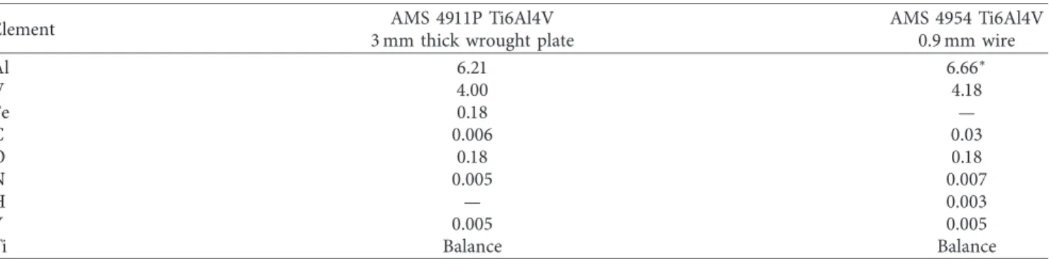
As defined by the design specifications for aeroengine turbine manufacturing, the material conditions (alloy, heat treatment, etc.) selected in this study consisted of using hot rolled and annealed TIMETAL
®
Ti6Al4V (AMS 4911P) wrought plate that had a composition, as given in Table 1. The substrate coupons for deposition were machined to dimensions of 120 mm in width, 55 mm in height, and 3 mm in thickness from the wrought Ti6Al4V plate. The height of the substrate coupon was oriented parallel to the RD of the Ti6Al4V plate (Figure 1(a)). The deposition surface on the substrate coupon was lightly sanded and cleaned with alcohol prior to clamping within the cooling platens mounted on the EBAM work-table. Weld beads were additively deposited on the substrate coupons using AMS 4954 Ti6Al4V filler wire with a diameter of 0.9 mm and a composition as listed in Table 1. The additive repair (emulating a blade product form) was conducted using a 42 kW Sciaky EBAM and/or welding system at the National Research Council of Canada that comprises an EB gun with an accelerating voltage of 60 kV, a wire feeding system, and positioning mechanisms (gantry and work-table) that are all housed within a chamber, roughly 1.7 m × 1.7 m × 2.1 m. EBAM was conducted in a vacuum environment with a pressure lower than 6.7 × 10⁻³Pa. The wire feed from a spool was directed axially into the focal point of the EB located on the deposited surface. Both the EB gun and wire feeding system were mounted onto an overhead positioning gantry that was capable of vertical-z displacement (0.76 m), translation along the y-axis (1.25 m), and tilting (−10°–90°). The substrate was placed within cooling platensclamped onto a T-slotted work-table capable of rotating (360°), tilting (−10–90°), and traversing along the x-axis
(0.76 m). Operating the EBAM system with real-time com-puter control, the process parameters, including the voltage, current, wire feed rate, and translation in the X- and Z-di-rections, were programmed to deposit the Ti6Al4V wire as a single bead onto the Ti6Al4V substrate so as to build layer by layer a straight wall to target minimum dimensions of 7 mm in height, 110 mm in width, and 3 mm in thickness (Figure 1(a)). To reach this build height, 20 layers of single beads were deposited (Figure 1(b)) at a linear heat input of 90 J/mm and wire deposition rate of 25 mm3/s. In total, 9 build coupons were fabricated (Figure 1). For each successive layer, the DD was reversed, as indicated in Figure 1(a). The
selected coordinate system designates the DD as “X,” the direction of the wall thickness as “Y,” and the direction of the wall height as “Z.”
After deposition, non-destructive testing of each build coupon was conducted according to the procedure described in [8, 25], using an XTek HMXST 225 X-ray CT system with Table 1: Composition of the Ti6Al4V materials (wt. %).
Element 3 mm thick wrought plateAMS 4911P Ti6Al4V AMS 4954 Ti6Al4V0.9 mm wire
Al 6.21 6.66∗ V 4.00 4.18 Fe 0.18 — C 0.006 0.03 O 0.18 0.18 N 0.005 0.007 H — 0.003 Y 0.005 0.005 Ti Balance Balance
∗Selected composition to compensate for evaporation of alloying elements during EBAM, especially aluminum.
3.0 mm 55.0 mm Electron beam Ti6Al4V wire Rolling direction (RD) 7.0 mm 110.0 mm 120.0 mm Deposition direction (DD) X Z Y (a) (b) Substrate Deposit Substrate Deposit Substrate Deposit Z (RD) X (DD) Y (T) DZ PMZ 55.0 mm 32.0 mm 1.0 mm 50.0 mm (c) (d)
Figure 1: (a) Coupon geometry, (b) deposited coupon showing columnar β across the layers, and (c) the vibration fatigue test specimens extracted from the Ti6Al4V deposit and substrate with their (d) geometry. It is noteworthy that the PM vibratory fatigue specimens were extracted from SRed Ti6Al4V plates (without deposition) and their depiction in (c) is to show the sample orientation only.
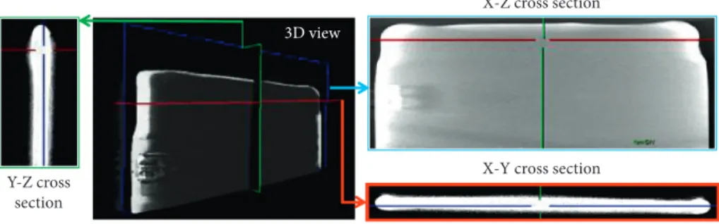
a voxel size of 6 µm and defect size detectability of ≥16 µm3 for visualization, to check that the Ti6Al4V deposited ma-terial had no interface or interlayer bonding concerns. Figure 2, a three-dimensional X-ray micro-CT scan of a representative Ti6Al4V deposited coupon, reveals that no indications were present in the various planes (X-Z, Y-Z, and X-Y). The high integrity of the EBAM deposits was also confirmed by destructive analysis through metallography that indicated the absence of defects.
A SR heat treatment was then applied to reduce the internal stresses, as well as distortion in the deposited Ti6Al4V wall builds and the substrate. The SR treatment consisted of heating the EBAM coupons to 700°C in a
vacuum furnace and soaking them at this temperature for 2 hours followed by argon gas (high purity grade, 99.999%) quenching to room temperature. It is noteworthy that the SR treatment was selected based on a standard industrial repair practice for aeroengine parts. The chemistry of the Ti6Al4V wall build in the as-deposited and SR conditions was 6.0% Al, 4.1% V, and the remainder Ti.
The Ti6Al4V build coupon was sectioned perpendicular to the deposition direction for metallographic investigation. Sample preparation involved automated grinding and pol-ishing techniques, as described in [8] for EBSD analysis with a Hitachi FEG-SEM using a voltage of 20 keV.
Vibration testing followed the methodology developed in [15] to closely represent the operational clamping and loading conditions on turbine engine blades. The method involved a piezoelectric shaker (Figure 3(a)) to provide a base excitation to a cantilevered plate so as to generate a high frequency resonant mode. FEM of a cantilevered plate, clamped and excited, along one edge (fixed-free-free-free1(fixed boundary condition in the clamping region and free boundary conditions for the remaining edges) boundary condition), was used to design and optimize the fatigue specimen geometry that would allow the common deformed shape of a two-stripe (4th harmonic) mode–hereafter re-ferred to as mode 4–with distinctive stripes of zero dis-placement at resonance; Figure 3(b) gives the normalized out-of-plane displacements, calculated by adjusting the modal mass to 1 in ANSYS with typical AMS 4911 data with due consideration of similar properties of EBAM Ti6Al4-V2(it is noteworthy that these FEM results were meant to reduce experimentation for estimating the frequency re-quirement for vibration in mode 4 and, as fulfillment of this requirement is verified during vibration testing, deviations between the predicted and actual frequencies for mode 4–from, for example, the assumption of similar properties for EBAM and wrought Ti6Al4V–simply impact the number of trial-and-error iterations needed), as reported in [8]. For this mode, the associated normalized von Mises stress contours (Figure 3(c)) show a high stress region at the midpoint of the free edge that is greater than the maximum stress along the clamped edge. This high stress region is usually denoted as the “fatigue zone,” as failure for this geometry is predicted to occur in this location for vibration in mode 4. This occurrence of the maximum stress state along a free edge is a prerequisite for achieving a mixed mode of a uniaxial stress state under fully reversed bending
[15], which is one of the main failure modes of blades [27]. These FEM results were generated for a 1 mm thick Ti6Al4V plate–32.0 mm wide by 50.0 mm long–and the resulting natural frequency was computed to be 6128 Hz.
To experimentally validate the FEM results, 27 vibra-tory fatigue specimens were extracted from the build coupons (Figure 1(b)) with this selected geometry, as depicted in Figure 1(c). Before vibration testing, the fatigue specimen faces and free edge were polished to a surface finish of 5 µm. A non-contact scanning laser vibrometer was used to measure the out-of-plane displacement at 206 predefined points (Figure 3(d)) on the fatigue specimen surface during excitation from frequencies of 2500 to 8000 Hz. At a frequency of 6320 Hz, the out-of-plane displacement map on the Ti6Al4V fatigue specimen re-sembled the FEM predictions (Figure (4)). Using the Dixon–Mood staircase method, the EBAM and wrought Ti6Al4V specimens were vibration tested sequentially at around 6320 Hz with a laser vibrometer measuring dis-placement to control the stress amplitude. It is noteworthy that calibration of the vibratory stress versus displacement was performed using instrumented specimens (a series of 5 gages, as shown in Figure 5) while resonating the fatigue specimen to define the relationship between the strain in the fatigue region and the velocity or displacement of the calibrated laser position, as illustrated in Figure 6. In doing so, precise measurement and control of the strain vibration amplitude or fatigue stress in the fatigue specimen was possible during vibration testing.
The first specimen was tested at a predefined strain vi-bration amplitude or stress level based on experience. The specimen was tested until it either failed or reached a life over 107cycles–the lifetime of interest selected in this study. During each test, cracking was confirmed using FPI and Figure 5 gives a representative image of this analysis.
Depending on whether the first specimen survived or failed, the stress level for the next specimen was, respectively, increased or decreased by a specific increment/step, Sd. This process was repeated until all specimens allocated for the testing were used. To analytically determine the mean (µ) and standard deviation (σ) based on staircase test data, Dixon–Mood [26] defined the following equations using maximum likelihood estimation and assuming a normal distribution: define: A � imax i�0 mi; B � imax i�0 i × mi; C � imax i�0 i2× mi, (1) μ � S0+ Sd× B A± 0.5 , (2) σ � 1.62 × Sd× A × C − B2 A2 +0.29 ifA × C − B 2 A2 ≥ 0.3 , (3) orσ � 0.53 × Sd if A × C − B2 A2 < 0.3 . (4)
Use of these equations for statistical analysis of the fa-tigue endurance limit data is exemplified in Figure 7 and Table 2 for the EBAM Ti6Al4V specimens that included 8 failures and 8 run-outs (survivals). In these equations, i is an integer that denotes the stress level and imaxcorresponds to
the highest level in the staircase. The equally spaced levels are sorted and numbered starting from the lowest stress level, S0. At level i, miis the number of specimens that either fail or
survive, depending upon which of these is the less frequent event (failure/run-out). Thus, if the majority of specimens
X-Z cross section
X-Y cross section Y-Z cross
section
3D view
Figure 2: X-ray micro-CT 3D scan of the Ti6Al4V deposited coupons showing no indications in X-Y, X-Z, and Y-Z planes.
Tip amplitude
measuring point Cantileveredplate sample
(a) Normal solution 1419 1168 918 668 418 168 –82 –332 –582 –832 STEP = 1 SUB = 5 FREQ = 6127.79 UY RSYS = 0 DMX = 1422.26 SEPC = 10.5936 SMN = –832.302 SMX = –1418.99 Fixed edge Ti-64 TP (W = 32 mm, L = 55 mm, T = 1.00 mm) X YZ (b) 0.144E + 7 0.128E + 7 0.112E + 7 0.963E + 6 0.802E + 6 0.642E + 6 0.481E + 6 0.321E + 6 0.160E + 6 0.139E – 4 X YZ Normal solution STEP = 1 SUB = 5 FREQ = 6127.79 SEQV (AVG) RSYS = 0 DMX = 1422.26 SMN = 0.130E – 04 SMX = 0.144E + 07
SMXB = 0.148E + 07 Fixed edge
Fatigue zone
Ti-64 TP (W = 32mm, L = 55mm, T = 1.00mm)
(c) (d)
Figure 3: (a) Piezoelectric shaker with clamped square cantilever plate, (b) out-of-plane displacements from the FEM calculations, (c) von Mises stress from the FEM calculations, and (d) measurement points with laser vibrometer.
fail, then the i � 0 level corresponds to the lowest stress level at which a specimen survives/run outs and micorresponds to the number of specimens that survive each stress level. By contrast, if the majority of specimens survive/run out at 107 cycles, then the i � 0 level corresponds to the lowest stress level at which a failure occurs and mi corresponds to the number of specimens that failed at each stress level. In (2), the plus sign is used when survivals are the less frequent event, while the minus sign is used if failures are the less frequent event. For the case of the EBAM Ti6Al4V data (Table 2) where the numbers of failure and survival events are equivalent, the analysis is possible using the specimens that either fail or survive. In the analysis illustrated in Ta-ble 2, EBAM Ti6Al4V data was treated as if the majority of specimens failed. For statistical analysis, three parameters, A, B, and C in (1) were then calculated as given in Table 2.
After vibration fatigue testing, select specimens that exhibited cracking, as confirmed by FPI, were prepared for metallographic examination, so as to microscopically ob-serve the crack initiation and propagation behavior in the EBAM Ti6Al4V and the Ti6Al4V plate.
3. Results and Discussion
3.1. Microstructure. Ti6Al4V is an allotropic alloy with two
dominant phases: HCP α and BCC β. Above the β transus temperature (typically above 950°C), the alloy transforms
fully to the single-phase β-field. Hence, heating the Ti6Al4V wire during EBAM to the melting temperature (∼1660°C)
generates a molten weld bead layer that solidifies first in the β
–125 –110 –95 –80 –65 –50 2500 3500 4500 5500 6500 7500 M agni tude (dB) Frequency (Hz) Color contour level
Mode 4 _ 0 + Fixed edge Fixed edge Fixed edge
Figure 4: Frequency response function during vibration fatigue testing of EBAM Ti6Al4V with related characteristic out-of-plane displacement maps measured with a scanning laser vibrometer that verify a mode 4 shape at ∼6320 Hz.
S/N Front side S/N 11 Front side P1 L1 P2 L2 Back side D at um A 5 strain gauges Crack initiation site
Figure 5: FPI image and method used to measure crack position (P1/P2) and length (L1/L2) in cracked HCF specimens.
y = 9728.2x R2 = 0.9975 y = 8684.3x R2 = 0.9954 y = 9172.9x R2 = 0.9977 0 500 1000 1500 2000 2500 3000 0.00 0.05 0.10 0.15 0.20 0.25 0.30 St ra in ( µp-p ) Laser displacement (mmp-p) Dataset 1 Dataset 2 Dataset 3
Figure 6: Strain versus laser displacement of the tip for three experimental datasets used for calibration.
500 550 600 650 700 1 2 3 4 5 6 7 8 9 10 11 12 13 14 15 16 St res s a m p li tude (MP a) Sample number Run-out Failure
Figure 7: Staircase diagram of fatigue stress data for EBAM Ti6Al4V specimens to show the applied Dixon–Mood method.
Table 2: Summations in Dixon–Mood method for the EBAM Ti6Al4V specimens. Level Stress (MPa) Failure Run-out, mi i·mi i 2·m i i � 3 (S3) 671 3 0 0 0 i � 2 (S2) 629 3 3 6 12 i � 1 (S1) 587 2 3 3 3 i � 0 (S0) 545 0 2 0 0 Sd�Si–Si-1�42 Sum A � 8 B � 9 C � 15
phase field. Below the β transus temperature, reversible transformation of the β phase occurs and the first α phase forms as an allotriomorph at the prior-β grain boundaries. The β phase fraction retained at room temperature and the α phase characteristics depend on the cooling rate experienced from the single-phase β-field. Typically, cooling rates above 410°C s−1 result in displacive (diffusionless) transformation of the β phase to a martensitic microstructure. At slower cooling rates, this transformation gradually changes and diffusion controlled Widmanst¨atten (basketweave) α forms between 20 and 410°C s−1 or lamellar (colony) α below 20 °C s−1.
As evidenced in Figure 1(b), as well as the room temperature EBSD microstructures in Figure 8, during the early stages (first few layers) of Ti6Al4V deposition with the wire-fed EBAM process, the prior-β grain formation characteristics evolve from fine and equiaxed to large and columnar. Figure 8(a) shows the very fine bimodal microstructure and rolled texture of the Ti6Al4V substrate that correlates well with its rolled and annealed state. In comparison, the first deposited layer consisted of fine equiaxed prior-β grains close to the Ti6Al4V PM interface (Figure 8(b)). In subsequent layers (Figure 8(c)) of the build, the equiaxed prior-β grain structure (∼85 µm in size) coarsened and was gradually replaced by columnar prior-β grain (∼830 µm in width) formation (Figure 8(d)). Within the prior-β grains (both fine equiaxed and columnar), α lamellae (∼1.31 ± 0.36 µm in size) formed as so-called colonies and resulted in a complex α/β lamellar microstructure and texture; in the interlamellar regions, the average β fraction was 9.6 % ± 0.9 %. This microstructure is typical for Ti6Al4V deposited using EB processes that experience slower cooling rates (than laser AM processes) during solidi-fication from the single-phase β-field and/or martensitic phase decomposition into lamellar α/β due to thermal cycling effects [8, 28].
3.2. High Cycle Fatigue. As HCF is characterized by elastic
deformation and is usually without macroscopic plastic deformation, the range of applied stress selected for fatigue testing is determined in its upper limit by the yield strength of the material. The lower bound of the stress range for fatigue testing is typically defined by the desired run-out time that allows finishing the test within a reasonable (short) time. In this present study, the selected stress range of 545 to 671 MPa was targeted for the (high cycle) lifetime regime of interest (up to 107cycles). It is noteworthy that the average yield strength in the z-direction for the wire-fed EBAM Ti6Al4V material was previously reported as 849 ± 13 MPa by the authors in [8].
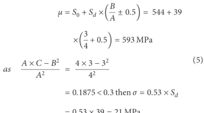
Figure 9 presents the HCF results under the vibration mode 4 obtained in this study. The first observation concerns the wrought Ti6Al4V plate specimens. Based on the Dix-on–Mood analysis, the staircase test data of the fatigue endurance limit for the wrought Ti6Al4V specimens was analyzed using (1)-(4), to calculate the mean and standard deviation as follows: μ � S0+ Sd× B A± 0.5 � 544 + 39 × 3 4+0.5 �593 MPa as A × C − B 2 A2 � 4 × 3 − 32 42 �0.1875 < 0.3 then σ � 0.53 × Sd �0.53 × 39 � 21 MPa. (5)
Thus, for the wrought Ti6Al4V specimens the estimated average fatigue limit was 593 MPa, the standard deviation was 21 MPa, and the lower fatigue limit (95% reliability) was 497 MPa (using an approved life limit factor of the engine manufacturer). These data point to a higher crack resistance than the reported value of about 500 MPa for the same AMS alloy under conventional fully reversed axial loading for 107 cycles [29] and roughly 510 MPa for vibration bending at 107 cycles that was extrapolated at 1800 Hz from [11]. This difference is believed to be due to the sensitivity in the loading condition exhibited by Ti6Al4V for tensile [30] and fatigue [31, 32] behaviors.
A second point to note is specific to the wire-fed EBAM Ti6Al4V, where the fatigue limit is more difficult to deter-mine as the data exhibited higher scattering in the life to failure. Using the staircase method (Figure 7 and Table 2) and (1)-(4), the mean and standard deviation were deter-mined as follows: μ � S0+ Sd× B A± 0.5 � 545 + 42 × 9 8+0.5 �613 MPa as A × C − B 2 A2 � 8 × 15 − 92 82 � 0.61 ≥ 0.3; then σ �1.62 × Sd× A × C − B2 A2 +0.29 σ � 1.62 × 42 ×(0.61 + 0.29) � 61 MPa. (6) Thus, the estimated average fatigue limit for the EBAM Ti6Al4V was 613 MPa, the standard deviation was 61 MPa, and the lower fatigue limit (95% reliability) was 426 MPa (using the engine manufacturer’s approved life limit factor). Presently, for Ti6Al4V fabricated by AM, the fatigue test data in open literature is limited in comparison to static tensile test data; needless to say, the overall data for beam/wire combinations is even less than powder-based processing. Some key insights are however emerging. A key factor is the build orientation. Brandl et al. [33] and Baufeld et al. [34] investigated uniaxial HCF strength of laser/wire specimens and reported different fatigue limits (at 107cycles) depending on the build orientation relative to mechanical
loading at a frequency of 100 Hz. Specifically, Baufield et al. [34] reported that the fatigue limit of X-built specimens was above 840 MPa, while Z-built specimens had a lower fatigue
limit (750 MPa) with a significant number of early failures (down to 3 × 10⁶). These fatigue tests were undertaken on specimens heat treated at 843°C, with a reported lamella width A1 A2 1120 max = 7.971 5.640 3.990 2.823 1.998 1.413 1.000 0.708 Titanium (alpha) 1010 100μm 0001 2110 (a) A1 A2 1120 Titanium (alpha) 1010 0001 2110 max = 4.824 3.711 2.855 2.196 1.690 1.300 1.000 0.769 100μm (b) A1 A2 1120 max = 4.753 3.665 2.827 2.180 1.681 1.297 1.000 0.771 Titanium (alpha) 1010 0001 2110 100μm (c) A1 A2 1120 max = 8.377 5.878 4.125 2.894 2.031 1.425 1.000 0.702 Titanium (alpha) 1010 0001 2110 100μm (d)
Figure 8: EBSD orientation maps of the α phase (with the respective color scheme) taken from the frontal XZ-plane of a Ti6Al4V build coupon and the corresponding (112̅0) contour pole figures: (a) wrought Ti6Al4V plate (substrate), (b) 1st layer next to the substrate with equiaxed prior-β grains, (c) 3rd layer with coarse equiaxed prior-β grains, and (d) 5th layer with columnar prior-β grains.
of 1 µm [33, 34]. However, as their uniaxial fatigue testing conditions remained at relatively low frequencies, the fatigue limits determined by Baufield et al. [34] are not representative of conditions experienced in gas turbine engine cold-section applications (high frequency, short wavelength stress states, and mixed-mode loading). Moreover, the reported fatigue limits in [34] for wire-fed laser deposited Ti6Al4V are in-dividual values rather than a mean endurance limit with a standard deviation, as obtained in the present work through statistical analysis of HCF dataset under vibration loading.
Ellyson et al. [17] carried out vibration fatigue testing of Ti6Al4V polished specimens fabricated by laser wire de-position in mode 1 at a frequency of 800 Hz and showed that, for a fine basketweave microstructure (high-speed laser wire deposition followed by heat treatment), there was no sig-nificant difference in fatigue limit at 107cycles between the two build orientations (i.e., X and Z). The microstructure was composed of prior-β grains of 1.3 mm ± 0.7 mm in width with an average α plate thickness of 0.5 μm ± 0.1 μm [35]. However, as their reported HCF results were normalized, no absolute comparison of the fatigue limit is possible with the current work.
To understand fatigue resistance in titanium alloys, a hierarchic structure of 3 possible factors: defects,
microstructure, and residual stresses3(the residual stresses in the as-built and SR conditions of the wire-fed EBAM Ti6Al4V material were previously identified by the authors in [8] to be quite low (<2% of the yield strength of the alloy); thus, in the present study, their role would not significantly factor into shaping the fatigue mechanisms. As such, the role of residual stresses on the fatigue behavior was not specif-ically differentiated in the present work) has been proposed and weighted based on their relative severity/impact on initiation and development of fatigue cracks. The domi-nating mechanism is fabrication defects, most commonly pores, but also this might include any cracks, lack of fusion, and/or inclusions. In the present work, all the wire-fed EBAM samples were scanned using X-ray CT (Figure 2) and identified not to have any of the porosity, cracks, or in-clusions that are possible under non-optimized process conditions [36]. Generally, low porosity is one of the ad-vantages of the wire deposition AM technology over PBF methods. Under this context (i.e., absence of fabrication defects), the next process-specific factor influencing the fatigue failure mechanisms and resistance is the micro-structural features in the AM material that encompass the various phase constituents and their heterogeneity. In ti-tanium alloys, microstructural features such as prior-β
450 500 550 600 650 700 750
1.0E + 04 1.0E + 05 1.0E + 06 1.0E + 07
F atigue s tr en gt h (MP a) Cycles to failure Run-out (wrought) Run-out (EBAM) Failure (wrought) Failure (EBAM)
Figure 9: Comparison of experimental fatigue data for EBAM Ti6Al4V with wrought equivalent Ti6Al4V.
Table 3: Crack position (mm) and length measurements (mm) from cracked EBAM HCF specimens (see Figure 5).
S/N Front side Back side
P1 L1 P2 L2 1 16.82 2.00 — — 2 15.52 2.02 — — 5 — — 16.26 1.68 6 — — 15.76 2.48 10 17.30 1.78 — — 11 — — 15.1 1.69 14 15.41 1.94 — — 16 16.56 4.12 — —
grains, α-colony size, and α platelet width can be competing variables responsible for crack initiation and propagation. As mentioned, the EBAM Ti6Al4V material consisted of a heterogeneous microstructure composed of columnar
prior-β grains (Figure 1(b)) within which colonies of α lamellae
were present (Figures 8(b)–8(d)). By examining the crack path in the EBAM Ti6Al4V specimens that cracked during vibration fatigue testing, the competing microstructure features responsible for crack initiation and propagation were studied. First, the location of the crack with respect to the position of the datum A (Figure 5) was examined for the specimens that cracked in fewer than 107cycles. Table 3 lists the measurements for crack position (P1/P2) and length (L1/ L2) for the different specimens. The values of P1/P2 indicate the position where the crack initiated close to the midpoint location of 16 mm in the fatigue zone (Figure 2(c)). The measured crack length (L1/L2) ranged between 1.7 and 4.1 mm in length inside the deposited region. These were then mounted, polished, and etched to examine the crack
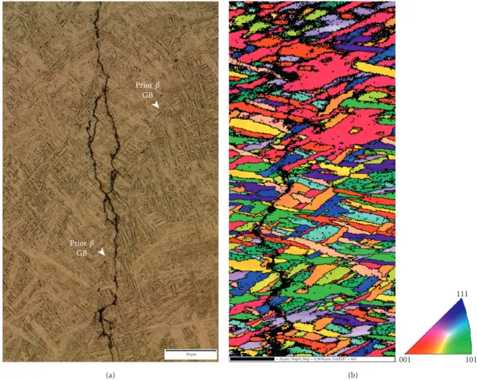
path through the microstructure of the EBAM Ti6Al4V. Figure 10(a) shows a representative stitched micrograph of the entire fatigue crack propagation region, while Figure 10(b) shows the corresponding HCF crack initiation site in EBAM Ti6Al4V. The crack initiates at the α-colonies on the surface of the fatigue specimen (in the fatigue zone) and propagates progressively through this α-colony struc-ture. The resulting crack path exhibits evidence of orienting towards prior-β grain boundaries–as the distance between the crack and the boundary can be seen to decrease from 200 µm at the initiation point on the specimen surface (Figure 10(b)) to ∼50 µm (Figure 10(c)). The fatigue crack path can also traverse prior-β grain boundaries, as shown in Figure 11(a). Thus, the fatigue crack path in EBAM Ti6Al4V is predominantly dependent on the α-colony structure, as can be reasoned clearly by examining the tortuous and deflecting cracking trajectories (Figure 11(b)). Specifically, when the axes of the α lamellae plates are oriented per-pendicular to the loading direction, the fatigue crack
Prior-β GB Prior-β GB 200 μm HCF crack (a) 20 μm
Surface crack initiation (b)
Prior-β GB
(c)
20 μm
Figure 10: Microphotographs showing (a) the fatigue crack path in a representative wire-fed EBAM Ti6Al4V specimen from (b) initiation on the surface in the region of the fatigue zone at α-colonies to progression by growth and propagation along the α-colony boundaries and through the α-colonies of lamellae, which manifested as (c) a deviating crack exhibiting high tortuosity.
propagates along the boundaries of α-colonies. By contrast, when the axes of the α lamellae plates are parallel to the loading direction, the fatigue crack propagates through the
α-colonies of lamellae (i.e., along interlamellar boundaries).
Similar observations of fatigue crack propagation at
α-colonies were reported for laser powder-fed [37] and laser
wire-fed [17] DED specimens, but with a relatively finer colony size ∼10–20 µm reported in [17]. As α-colonies form by means of similarly aligned fine lamellae/platelets, there is a significant misorientation present between the colonies. Thus intersections of α-colonies are preferred initiation sites stemming from their short distance for crack propagation. By contrast, the fatigue crack in the bimodal micro-structure of the Ti6Al4V wrought plate showed practically no deviation or tortuosity (Figure 12). The crack was ob-served to preferentially initiate at interconnected primary α grain boundaries, which is reasonable considering that nucleation and growth are controlled by strain accumulation at the tips of the longest slip band [38]. The fatigue crack then continued to propagate along the primary α bound-aries, particularly along interconnected primary α grains. In the present work, the bimodal structure of PM appeared to consist of a high percentage of interconnected primary α,
which would have resulted in a large effective slip length and contributed to lowering the fatigue limit. This finding agrees with reported studies on titanium alloys that have recog-nised the role of similarly oriented primary α phase grains on increasing the slip length and contributing as microstruc-tural weak links that drive fatigue initiation and propagation behavior [39–41].
Interestingly, in the microstructure-properties rela-tionship paradigm for Ti6Al4V, it is well accepted that a finer microstructure will provide improved strength and ductility. Thus, it is also well accepted that all microstructural features that contribute to increasing the yield strength and/or re-ducing the dislocation slip length should also improve HCF strength [42], considering its key role to restrain the dis-location motion [43, 44]. According to [44], the most im-portant factor for increasing the HCF strength is to reduce the maximum dislocation slip length and thus the α lath size. The microstructure obtained in the current work is com-posed of prior-β grains with a width of ∼830 µm and α laths of ∼1.31 ± 0.36 µm in size. In comparison, the microstructure of laser wire-fed DED consisted of α laths varying between 0.5 and 0.8 µm [17], roughly half the size of the wire-fed EBAM Ti6Al4V. Despite such a large difference in the α plate
Prior-β GB Prior-β GB 50 μm (a)
= 20μm; Map4; Step = 0,3636μm; Grid207 × 441 001 101
111
(b)
Figure 11: Fatigue crack path in another representative wire-fed EBAM Ti6Al4V specimen that traversed both along the α-colony boundaries and through the α-colonies of lamellae, irrespective of the presence of a prior-β GB: (a) optical image and (b) EBSD image.
size, which fosters important tensile mechanical properties differences, the size and the orientation mismatch between the colonies remains the preferred crack propagation path in HCF for the EBAM Ti6Al4V.
4. Conclusions
The results of this study were targeted to develop an ad-vanced repair solution for fatigue critical cold-section gas turbine parts by understanding the vibratory fatigue be-havior of Ti6Al4V deposited using wire-fed EBAM. The following conclusions can be drawn from this work.
(1) Wire-fed EBAM Ti6Al4V deposits exhibited a co-lumnar prior-β grain structure with a lamellar mi-crostructure consisting of colonies of α lamellae, averaging 1.31 ± 0.36 µm in size.
(2) The HCF results determined through vibration testing indicated a higher average fatigue endurance limit and standard deviation for the EBAM Ti6Al4V (613 MPa and 61 MPa) compared to the wrought counterpart (593 MPa and 21 MPa).
(3) The lower fatigue limit (95% reliability) for the EBAM Ti6Al4V was 426 MPa, which was lower than
the value of 497 MPa determined for wrought Ti6Al4V and was attributed to the slightly higher data scatter of the former material.
(4) In the absence of manufacturing defects in the EBAM Ti6Al4V, the fatigue mechanisms were de-pendent on process-specific microstructural fea-tures, predominantly the α-colony structure. By contrast, the crack path in the bimodal micro-structure of the wrought Ti6Al4V plate was along the primary α boundaries, particularly along inter-connected primary α grains.
(5) Analysis of the deflected and tortuous fatigue crack path in cracked EBAM Ti6Al4V showed evidence of propagation both along α-colony boundaries and through α-colonies of lamellae depending on the orientation (perpendicular versus parallel) of the lamellae relative to the loading axes.
Abbreviations
AM: Additive manufacturing BCC: Body-centered cubic CT: Computerized tomography 200 μm HCF crack (a) (c) Primary α Primary α 20 μm (b) Interconnected primary α 20 μm
Figure 12: Microphotographs showing the fatigue crack path in the PM that traverses along the primary α boundaries in the bimodal microstructure of the wrought Ti6Al4V plate: (a) stitched image of crack, (b) crack initiation region, and (c) relatively straight crack path without deflections.
DD: Deposition direction DED: Direct energy deposition DMLS: Direct metal laser sintering EB: Electron beam
EBAM: Electron beam additive manufacturing EBSD: Electron backscatter diffraction
FEG-SEM:
Field emission gun scanning electron microscope
FEM: Finite element modelling FOD: Foreign object damage
FPI: Fluorescent penetrant indication GB: Grain boundary
HCF: High cycle fatigue HCP: Hexagonal closely packed L1/L2: Crack length (front/back) N: Number of cycles to failure P1/P2: Crack position (front/back) PBF: Powder bed fusion
PM: Parent material p-p: Peak-to-peak RD: Rolling direction S: Stress
S0: Lowest stress level Sd: Stress increment/step SLM: Selective laser melting SR: Stress relief
α: Alpha
β: Beta
µ: Mean fatigue endurance limit
σ: Standard deviation.
Data Availability
The data used to support the findings of this study are in-cluded within the article.
Conflicts of Interest
The authors declare that there are no conflicts of interest regarding the publication of this paper.
Acknowledgments
This work was supported by the Defence Technologies and Sustainment Program of the National Research Council of Canada (NRC) and the Annual Research Program of IHI Corporation. The authors are grateful to X. Pelletier and X. Lin at NRC for supporting the EBAM trials and metallography of the fatigue cracks, as well as C. Bescond for supporting the X-ray micro-CT measurements. The authors are also grateful to N. Yoshino of IHI Corporation for supporting the vibration fatigue testing. Finally, the authors are grateful to C. de Formanoir and S. Godet (Universit´e Libre de Bruxelles) for the EBSD images of the build coupon.
References
[1] J. O. Peters and R. O. Ritchie, “Foreign-object damage and high-cycle fatigue of Ti-6Al-4V,” Materials Science and
En-gineering: A, vol. 319-321, pp. 597–601, 2001.
[2] J. O. Peters and R. O. Ritchie, “Foreign-object damage and high-cycle fatigue: role of microstructure in Ti–6Al–4V,”
International Journal of Fatigue, vol. 23, pp. S413–S421, 2001.
[3] J. O. Peters, B. L. Boyce, A. W. Thompson, R. O. Ritchie, and O. Roder, “Role of foreign-object damage on thresholds for high-cycle fatigue in Ti-6Al-4V,” Metallurgical and Materials
Transactions A, vol. 31, no. 6, pp. 1571–1583, 2000.
[4] P. C. Patnaik, M. R. Pishva, J. E. Elder, W. Doswell, and R. Thamburaj, “Repair and life extension of titanium alloy fan blades in aircraft gas turbines,” in Proceedings of the ASME
1989 International Gas Turbine and Aeroengine Congress and Exposition, ASME, Toronto, Canada, June 1989.
[5] P. Azar, P. Li, P. C. Patnaik, R. Thamburaj, and J.-P. Immarigeon, “Electron beam weld repair and qualifi-cation of titanium fan blades for military gas turbine engines,” in Proceedings of the NATO-RTO-MP-69 Specialists’ Meeting
on Cost Effective Application of Titanium Alloys in Military Platforms, pp. 18–21, Loen, Norway, 2001.
[6] L. Portol´es, O. Jord´a, L. Jord´a, A. Uriondo, M. Esperon-Miguez, and S. Perinpanayagam, “A qualification procedure to manufacture and repair aerospace parts with electron beam melting,” Journal of Manufacturing Systems, vol. 41, pp. 65– 75, 2016.
[7] N. K. Dey, F. W. Liou, and C. Nedic, “Additive manufacturing laser deposition of Ti-6Al-4V for aerospace repair applica-tions,” in Proceedings of the Solid freeform fabrication, pp. 853–858, Austin, TX, USA, 2013.
[8] P. Wanjara, K. Watanabe, C. de Formanoir et al., “Titanium alloy repair with wire-feed electron beam additive manufacturing technology,” Advances in Materials Science
and Engineering, vol. 2019, Article ID 3979471, 23 pages, 2019.
[9] W. E. Frazier, “Metal additive manufacturing: a review,”
Journal of Materials Engineering and Performance, vol. 23,
no. 6, pp. 1917–1928, 2014.
[10] A. Uriondo, M. Esperon-Miguez, and S. Perinpanayagam, “The present and future of additive manufacturing in the aerospace sector: a review of important aspects,” Proceedings
of the Institution of Mechanical Engineers, Part G: Journal of Aerospace Engineering, vol. 229, no. 11, pp. 2132–2147, 2015.
[11] O. Scott-Emuakpor, C. Holycross, T. George, K. Knapp, and J. Beck, “Fatigue and strength studies of titanium 6Al–4V fabricated by direct metal laser sintering,” ASME Journal of
Engineering for Gas Turbines and Power, vol. 138, no. 2, Article
ID 022101, 2016.
[12] C. M. Holycross, R. Srinivasan, T. J. George, S. Tamirisakandala, and S. M. Russ, “High frequency vibration based fatigue testing of developmental alloys,” in Fatigue of
Materials II: Advances and Emergences in Understanding,
T. S. Srivatsan, M. A. Imam, and R. Srinivasan, Eds., pp. 39–46, Springer, Cham, Switzerland, 2012.
[13] B. A. Cowles, “High cycle fatigue in aircraft gas turbines-an industry perspective,” International Journal of Fracture, vol. 80, no. 2-3, pp. 147–163, 1996.
[14] S. Madhavan, R. Jain, C. Sujatha, and A. S. Sekhar, “Vibration based damage detection of rotor blades in a gas turbine en-gine,” Engineering Failure Analysis, vol. 46, pp. 26–39, 2014. [15] T. George, J. Seidt, M.-H. H. Shen, T. Nicholas, and C. J. Cross, “Development of a novel vibration-based fatigue
testing methodology,” International Journal of Fatigue, vol. 26, no. 5, pp. 477–486, 2004.
[16] B. Ellyson, M. Brochu, and M. Brochu, “Characterization of bending vibration fatigue of SLM fabricated Ti-6Al-4V,”
International Journal of Fatigue, vol. 99, pp. 25–34, 2017.
[17] B. Ellyson, N. Chekir, and M. Brochu, “Characterization of bending vibration fatigue of WBD fabricated Ti-6Al-4V,”
International Journal of Fatigue, vol. 101, pp. 36–44, 2017.
[18] J. Gockel, J. Beuth, and K. Taminger, “Integrated control of solidification microstructure and melt pool dimensions in electron beam wire feed additive manufacturing of Ti-6Al-4V,” Additive Manufacturing, vol. 1–4, pp. 119–126, 2014. [19] J. Gockel, J. Fox, J. Beuth, and R. Hafley, “Integrated melt pool
and microstructure control for Ti-6Al-4V thin wall additive manufacturing,” Materials Science and Technology, vol. 31, no. 8, pp. 912–916, 2015.
[20] K. M. B. Taminger, R. A. Hafley, and D. L. Dicus, “Solid freeform fabrication: an enabling technology for future space missions,” in Proceedings of International Conference on Metal
Powder Deposition for Rapid Manufacturing, pp. 51–60, San
Antonio, TX, USA, 2002.
[21] P. Wanjara, M. Brochu, and M. Jahazi, “Electron beam freeform fabrication on stainless steel,” Thermec 2006, vol. 539–543, pp. 4938–4943, 2007.
[22] P. Wanjara, M. Brochu, and M. Jahazi, “Electron beam freeforming of stainless steel using solid wire feed,” Materials
& Design, vol. 28, no. 8, pp. 2278–2286, 2007.
[23] P. Wanjara, M. Brochu, S. Girard, and M. Jahazi, “Electron beam freeforming on type 321 stainless steel using BNi-2 brazing paste,” Materials Science and Technology, vol. 21, no. 5, pp. 613–618, 2005.
[24] S. Stecker, K. W. Lachenberg, H. Wang, and R. C. Salo, “Advanced electron beam free form fabrication methods and technology,” in Proceedings of FABTECH and AWS Welding
Show, pp. 35–46, Atlanta, GA, USA, 2006.
[25] P. Wanjara, J. Gholipour, C. Bescond, K. Watanabe, and K. Nezaki, “Characteristics of Ti6Al4V repair using electron beam additive manufacturing,” in Proceedings of the
NATO-STO-AVT-258 Specialists’ Meeting on Additive Manufacturing for Military Hardware, pp. 16–21, Tallinn, Estonia, 2016.
[26] W. J. Dixon and A. M. Mood, “A method for obtaining and analyzing sensitivity data,” Journal of the American Statistical
Association, vol. 43, no. 241, pp. 109–126, 1948.
[27] L. Guokang, W. Weidong, W. Fuxian, and Z. Hongjian, “Vibration fatigue probabilistic life prediction model and method for blade,” Transactions of Nanjing University of
Aeronautics and Astronautics, vol. 35, no. 3, pp. 494–506,
2018.
[28] M. Simonelli, Y. Y. Tse, and C. Tuck, “On the texture for-mation of selective laser melted Ti-6Al-4V,” Metallurgical and
Materials Transactions A, vol. 45, no. 6, pp. 2863–2872, 2014.
[29] ASM Handbook, Fatigue and Fracture, ASM International, Materials Park, OH, USA, 1996.
[30] T. Nicholas, “Tensile testing of materials at high rates of strain,” Experimental Mechanics, vol. 21, no. 5, pp. 177–185, 1981.
[31] R. Morrissey, D. McDowell, and T. Nicholas, “Frequency and stress ratio effects in high cycle fatigue of Ti-6Al-4V,”
In-ternational Journal of Fatigue, vol. 21, no. 7, pp. 679–685,
1999.
[32] E. Takeuchi, Y. Furuya, N. Nagashima, and S. Matsuoka, “The effect of frequency on the giga-cycle fatigue properties of a Ti-6Al-4V alloy,” Fatigue & Fracture of Engineering Materials &
Structures, vol. 31, no. 7, pp. 599–605, 2008.
[33] E. Brandl, B. Baufeld, C. Leyens, and R. Gault, “Additive manufactured Ti-6Al-4V using welding wire: comparison of laser and arc beam deposition and evaluation with respect to aerospace material specifications,” Physics Procedia, vol. 5, pp. 595–606, 2010.
[34] B. Baufeld, E. Brandl, and O. van der Biest, “Wire based additive layer manufacturing: comparison of microstructure and mechanical properties of Ti-6Al-4V components fabri-cated by laser-beam deposition and shaped metal deposition,”
Journal of Materials Processing Technology, vol. 211, no. 6,
pp. 1146–1158, 2011.
[35] N. Chekir, Y. Tian, R. Gauvin, N. Brodusch, J. J. Sixsmith, and M. Brochu, “Effect of travel speed and stress relief on thin Ti-6Al-4V laser wire deposits,” Materials Science and
Engi-neering: A, vol. 724, pp. 335–347, 2018.
[36] D. L´evesque, C. Bescond, M. Lord, X. Cao, P. Wanjara, and J.-P. Monchalin, “Inspection of additive manufactured parts using laser ultrasonics,” in Proceedings of the AIP Conference
Proceedings, Atlanta, Georgia, vol. 1706, pp. 130003–130009,
July 2016, doi: 10.1063/1.4940606.
[37] A. J. Sterling, B. Torries, N. Shamsaei, S. M. Thompson, and D. W. Seely, “Fatigue behavior and failure mechanisms of direct laser deposited Ti–6Al–4V,” Materials Science and
Engineering A, vol. 655, pp. 100–112, 2016.
[38] R. K. Nalla, R. O. Ritchie, B. L. Boyce, J. P. Campbell, and J. O. Peters, “Influence of microstructure on high-cycle fatigue of Ti-6Al-4V: bimodal vs. lamellar structures,” Metallurgical
and Materials Transactions A, vol. 33, no. 3, pp. 899–918,
2002.
[39] A. L. Pilchak, J. Shank, J. C. Tucker, S. Srivatsa, P. N. Fagin, and S. L. Semiatin, “A dataset for the development, verifi-cation, and validation of microstructure-sensitive process models for near-alpha titanium alloys,” Integrating Materials
and Manufacturing Innovation, vol. 5, no. 1, pp. 259–276,
2016.
[40] A. W. Bowen, “The influence of crystallographic orientation on fatigue crack growth in strongly textured Ti-6A1-4V,” Acta
Metallurgica, vol. 23, no. 11, pp. 1401–1409, 1975.
[41] W. Evans, J. Jones, and M. Whittaker, “Texture effects under tension and torsion loading conditions in titanium alloys,”
International Journal of Fatigue, vol. 27, no. 10-12,
pp. 1244–1250, 2005.
[42] R. Boyer, E. W. Collings, and G. Welsch, Materials Properties
Handbook: Titanium Alloys, ASM International, Materials
Park, OH, USA, 2nd ed. edition, 1998.
[43] G. L¨utjering and J. C. Williams, Titanium, Springer, Berlin, Germany, 2003.
[44] J. C. Williams and G. L¨utjering, Titanium’80 Science and