)
The Alewife Secondary Storage Subsystem
byWilson John Chan
Submitted to the Department of Electrical Engineering and Com-puter Science in partial fulfillment of the requirements for the
degrees of
BACHELOR OF SCIENCE and
MASTER OF SCIENCE at the
MASSACHUSETTS INSTITUTE OF TECHNOLOGY August 28, 1994
© Massachusetts Institute of Technology, 1994. All Rights Reserved.
Author ... _ ... .
.
...Wilson John Chan August 28, 1994
Certified by ...
Certified .. Professor Anant Agarwal Thesis Supervisor Department erfTEectrical Engineering and Computer Science
Accepted by ...
| - }JJ Professor F.R. Morgenthaler
\
Chair, Depatment Committee on Graduate Students Department of Electrical Engineering and Computer ScienceThe Alewife Secondary Storage Subsystem
by
Wilson John Chan
Submitted to the Department of Electrical Engineering and Com-puter Science on August 26, 1994, in partial fulfillment of the requirements for the degrees of Bachelor of Science and Master of
Science
Abstract
The Alewife Secondary Storage Subsystem is a high-performance, scalable, parallel file-system implemented on the Alewife Multiprocessor. The Unix-like filefile-system uses the cli-ent-server model and is distributed on all computation nodes to achieve maximum
parallelism. Disk Block Servers, implemented on the SCSI interface node, serves disk blocks to the computation nodes. Data is automatically striped across all available disks to enhance performance.
Thesis Supervisor: Anant Agarwal
Table of Contents
1 Introduction ... 6
1.1 Organization of this thesis ... 6
2 Overview . ...7
2.1 The Alewife Multiprocessor ... 7
2.2 Parallel Disk Systems ... 7
2.2.1 Single-Server Network File System (NFS) ...8
2.2.2 Redundant Arrays of Inexpensive Disks (RAID) ... 10
2.2.3 TickerTAIP ... ... ... ... 12
2.2.4 Zebra and RAID-II ... 12
2.3 Summary ... 14
3 Software ... ... 15
3.1 Overview of the Alewife Filesystem ... ... ... 16
3.2 Application Interface ... 19
3.3 The Filesystem Layer ... 21
3.3.1 The Generic Filesystem ... 21
3.4 The Alewife Filesystem ... 21
3.4.2 Locating Files ... 21
3.4.3 Allocating and Freeing Space ... 23
3.4.4 Communicating with the Disk Block Servers ...23
3.4.5 Startup Initialization ... 25
3.5 Disk Block Server . ... ... 26
3.5.6 IPI Message-In Handler ... 6
3.5.7 Cache Module ... ...28
3.5.8 SCSI Driver ...29
3.5.9 IPI Message-Out Handler ... 29
3.6 Summary ... ... ... .. ... 29
4 Hardware ... ... ... ... ... ...30
4.1 Disk Interface Board ... ... ... 31
Table of Contents
4.1.2 SCSI Controller Chip ... 32
4.2 D isk Drives ... 33
5 Perform ance and Conclusion ... 35
5.1 Single Client Results ... 35
5.2 Tw o-Client Results ... .... ... 40
5.3 Conclusion ...40
List of Figures
Figure 2.1: Block diagram of a single-server Network File System ...9
Figure 2.2: Implementing NFS on the Alewife Multiprocessor ...10
Figure 2.3: Basic RAID architecture ... 10
Figure 2.4: Implementing RAID on the Alewife Multiprocessor ... 11
Figure 2.5: TickerTAIP array architecture ... 13
Figure 2.6: Zebra network filesystem ... 13
Figure 2.7: Implementing RAID-II and Zebra on Alewife ...14
Figure 3.1: Block diagram of the Alewife Filesystem ... 16
Figure 3.2: Software organization of the Alewife Filesystem ... 17
Figure 3.3: Logical Interfaces of the Alewife Filesystem ... 18
Figure 3.4: Example layout of the file /usr/bin ... 22
Figure 3.5: Format of a relative IPI packet ... 24
Figure 3.6: Basic format of Disk Request Packets ... ... 25
Figure 3.8: Internal data flow of the Disk Block Server ... 27
Figure 4.1: Hardware Organization of Alewife ... 30
Figure 4.2: Block diagram of the Alewife Disk Interface Board ... 32
Figure 5.1: Setup of the Storage Subsystem for experimentation ...35
Figure 5.2: Single-processor cached-read results ... 36
Figure 5.3: Improving cached-read performance ... 36
Figure 5.4: Single-processor write results ... 37
Figure 5.5: Single-processor uncached-read results ... 37
Figure 5.6: Improving uncached-read performance ... 38
Figure 5.7: Cycle breakdown by operations ... 38
Figure 5.8: Cycle breakdown with seek ... 39
Chapter 1: Introduction
The processing power of microprocessors is doubling every two years but the speed of disk storage is failing to keep up. As a result, the secondary storage system has become the bottleneck in computing. The most promising solution is the Redundant Arrays of Inex-pensive Disks (RAID)[16] and its variants. Instead of accessing a single disk drive at a time, a computer with RAID accesses many disks simultaneously, effectively multiplying the bandwidth. A great deal of research is being done on parallel disk architecture and on filesystem organization to increase reliability and performance[3][7] [10][11][14].
This thesis project implements a high-performance, scalable disk storage subsystem for the Alewife Multiprocessor[2]. Scalability has been the main design goal for Alewife. With the Alewife Secondary Storage Subsystem, disks can be added to increase both capacity and performance. This thesis also shows that the Alewife Multiprocessor, with its unique set of features, is an ideal platform for storage architecture research.
1.1 Organization of this thesis
This thesis is divided into five chapters. A survey of existing parallel storage architectures is given in "Overview". In addition, examples showing how these architectures can be implemented on Alewife are given. The "Software" chapter describes, in detail, the file-system that has been implemented in this thesis project. The "Hardware" chapter describes the implementation of the disk controller. Last but not least, some performance numbers are presented in the "Performance and Conclusion" chapter.
Chapter 2: Overview
A great deal of research effort is being focused on disk storage systems. The advent of multimedia applications has placed more demand on the capacity and bandwidth of stor-age systems. Capacity on the order terabytes (1012) and bandwidth of several gigabytes/s (109) are needed to support the next generation of applications such as movie-on-demand and multimedia databases. This chapter gives an overview of parallel disk systems which are aimed at increasing the performance of storage systems. In addition, several examples showing how these systems can be implemented on the Alewife Multiprocessor are given. With its flexibility and scalability, Alewife is an ideal platform for storage architecture research.
2.1 The Alewife Multiprocessor
The Alewife Multiprocessor is a scalable, mesh-network based, cache-coherent, distrib-uted shared-memory parallel computer[2]. Alewife can have up to 512 processors working in parallel. These processors communicate with each other over a low-latency (1004ns), high-speed (up to 100MB/s) mesh network. Each processor has access to both local and globally-shared memory. The most unique feature is that the globally-shared memory is distributed throughout the machine. Access to the shared memory is controlled by the Cache Memory Management Unit (CMMU). Essentially, the CMMU translates a shared-memory access into a message to the processor node that contains the data. Coherency of shared data is maintained in the CMMU and in software using the LimitLESS protocol[4]. The message-passing paradigm is also supported at the user and operating-system levels.
2.2 Parallel Disk Systems
can be divided, conceptually, into three layers. The low-level software, or driver, controls the storage device directly. The mid-level software implements caching to speed storage transactions. With caching, frequently used information is stored in high-speed memory to minimize disk accesses. The high-level filesystem software structures the raw data on the storage device into files and directories. This high-level software can further be divided into two components; one deals with the metadata-the extra data needed to locate a file-and the other deals with the actual file data. By distributing file-and replicating these software layers and the physical storage devices, parallel disk systems of different characteristics can be constructed.
The following subsections discuss some commercial and experimental parallel disk systems which are implemented with a combination of custom hardware and commodity workstations. Using Alewife and the Storage Subsystem, these and other storage architec-tures can be implemented and tested more cost-effectively.
2.2.1 Single-Server Network File System (NFS)
The simplest type of network-based filesystem is the single-server Network File Sys-tem, or NFS, from SUN Microsystems[18]. Figure 2.1 shows a diagram of single-server NFS, in terms of the three software layers discussed above, connected to several clients over a network. In the single-server NFS, all three layers reside on the same computer. When a client workstation wants to access a file, it sends a request to the NFS server. The request contains the name of the file, access mode, and information necessary to perform file protection. The server searches the metadata-the extra data needed to locate a file-for the location of the file and sends the file data back to the client.
There are advantages and disadvantages in using a centralized network server. First, administration is simplified. If more capacity is needed, for instance, disks can be added to the server. If files get corrupted, only the server needs to be checked. Second, a
single-Figure 2.1: Block diagram of a single-server Network File System.
server filesystem has smaller overhead than a filesystem with multiple servers. Since all the filesystem software runs on one machine, communication overhead is kept at a mini-mum because intermediate data needed to access files is stored locally. On the other hand, if the server fails, all its clients will not have access to the files. More importantly, with the NFS server being the bottleneck, the performance degrades quickly as the load goes up. NFS can be made into a parallel disk system by physically adding more file servers onto the network. These servers are addressed by the user applications. In other words,
parallel-ism is managed explicitly by the user.
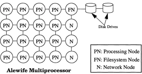
Implementing NFS on the Alewife Multiprocessor is trivial. Figure 2.2 shows such a NFS setup on a 16-node Alewife machine. In this configuration, all filesystem requests are sent directly to the Filesystem Node, FN, which executes the top-, middle- and low-level software. The Processing Nodes, PN, correspond to the clients in Figure 2.1. All the nodes are connected in a mesh network. The Network Nodes, N, merely routes data from their corresponding row to the Filesystem Node. They are needed because Alewife uses a fixed X-Y routing scheme to avoid deadlock; data sent over the network has to travel in the hor-izontal direction first and then in the vertical direction.
Alewife Multiprocessor
Figure 2.2: Implementing NFS on the Alewife Multiprocessor.
In this configuration, file requests from the Processing Nodes are routed to the Filesys-tem Node. The FilesysFilesys-tem Node looks up where the file is on the disk drives, and then sends the data back to the requester.
2.2.2 Redundant Arrays of Inexpensive Disks (RAID)
RAID increases storage subsystem speed by performing accesses to multiple disk drives simultaneously[16]. The system in Figure 2.3 increases the throughput by a maximum of N times over a single-server filesystem. In reality, the speedup is less than N due to house-keeping overhead. The overhead includes parity calculation, partial-write update, and con-troller bottleneck.
Parity is used to enhance the fault tolerance of the system. A system with N disk drives has a theoretical mean-time-between-failure (MTBF) N times greater than that with a
sin-high-speed,
,.
disk drives
network interface
-I 0 Total of N
Io H D- Wdisk drives
Figure 2.3: Basic RAID architecture.
sing Node stem Node N' Nptxunrl Nnrl
PN: Processing Node
Alewife Multiprocessor
Figure 2.4: Implementing RAID on the Alewife Multiprocessor.
gle disk drive. With MTBF of a disk drive averaging about 200,000 hours, a system with hundreds of disk drives clearly has an unacceptable reliability. Furthermore, all the data is rendered useless once a disk fails. To reduce the failure rate, a checksum, or parity, is cal-culated and stored on the disk subsystem at every write access. In case of a failure of a sin-gle disk, data can be recovered using this parity. The downside is that every write access incurs some overhead in both space and time.
Small writes incur a great deal of overhead. The basic unit of data in a RAID system, called a stripe, is normally spread across all N disk drives. When the filesystem rewrites data that is less than a stripe in length, the RAID controller must retrieve the old data, modify it with the new data, and recalculate the parity for that stripe. This partial-write update effectively reduces the write performance by more than 50%.
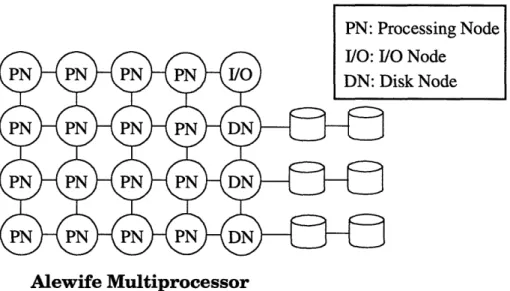
RAID can be implemented on Alewife using the configuration shown in Figure 2.4. File requests are made to the I/O Node in this configuration. By reading the metadata on the disks, the I/O Node determines where the file is stored. The file data is then sent to the requester. Bear in mind that the metadata and file data are striped across the three disks to
/O Node )isk Node
boost bandwidth. This configuration has two advantages over the Berkeley implementa-tion of RAID. First, the Alewife implementaimplementa-tion has more network connecimplementa-tions than the Berkeley RAID. A single network connection quickly becomes the bottleneck of the sys-tem as the load goes up[5]; having multiple-network connections improve both read and write performance compared to the Berkeley RAID. Second, each Alewife Disk Node contains a RISC microprocessor which allows parity calculation-the bottleneck of
writes-to be performed in parallel across the Disk Nodes.
Management of metadata is still a bottleneck in both the Alewife and Berkeley imple-mentations of RAID, and, of course, in NFS. Opening, closing and locating files require the intervention of the central server. RAID-II and Zebra, discussed below, reduce this contention by distributing the storage of metadata onto multiple file servers.
2.2.3 TickerTAIP
TickerTAIP extends the traditional, or centralized, RAID architecture by incorporating an array controller into every string of disks[3] (Figure 2.5). The array controllers, communi-cate through a small area network, perform parity calculation and fault recovery in a dis-tributed fashion. Communication with the host computer, where the filesystem resides, is through one or more network links. TickerTAIP improves the robustness of the storage system by exploiting physical redundancy. In terms of performance, TickerTAIP improves the response time of large file writes by distributing the parity computation among several processors. The TickerTAIP architecture does not specify the higher-level filesystem run-ning on top of the RAID layer.
2.2.4 Zebra and RAID-II
Zebra[7] and RAID-II[14] improves the performance of the basic RAID architecture by distributing the storage of file data and metadata, and more significantly, by using a
log-Figure 2.5: TickerTAIP array architecture.
structured filesystem (LFS). In Zebra and RAID-II, file data is stored in storage servers and metadata is stored in the file manager (Figure 2.6). By decoupling metadata and file data storage, the file servers can be optimized for each type of access pattern. Metadata accesses tend to be small and random; file data accesses tend to be sequential and large. By distributing their storage onto different servers, caching- and layout-policies can be tai-lored to their access patterns. Each type of server can be further partitioned into RAID to boost performance. Moreover, the separation of the storage of metadata and file data allows the filesystem to be scalable. If it turns out that more bandwidth is needed for file data, mostly as a result of frequent large file accesses, more data servers can be added. If it turns out that the metadata servers are overutilized-a result of frequent small, random file accesses-more metadata servers can be added[[14]. LFS further increases write
perfor-,aner
Server
mance by eliminating partial-write updates. When the filesystem overwrites data that occupies less than a stripe, it has to read the old data in the stripe, modify it with the new data, and write back the stripe. LFS eliminates this time-consuming process by bundling many small writes together and writing them to a new stripe. The stripes with old data are periodically deleted by the strip cleaner.
Figure 2.7 shows how RAID-II and Zebra can be implemented using the Alewife Mul-tiprocessor. File "open" and "close" requests are sent to the Metadata Server (called File Server in RAID-II and File Manager in Zebra). The Metadata Server searches for the loca-tion of the file and sends back the informaloca-tion to the requester. When the requester wants to read or write the previously-opened file, it passes this location information to the Data Server to obtain the file data. In comparison, read and write accesses in both RAID-II and Zebra have to go through the metadata servers to obtain the storage location.
2.3 Summary
The Alewife Multiprocessor, with its versatility and scalability, is an ideal platform for storage architecture research. The following chapters describes the high-performance, scalable storage subsystem that has been implemented on Alewife.
Alewife Multiprocessor
Figure 2.7: Implementing RAID-II and Zebra on Alewife.
PN: Processing Node Srd Metadata Server
Chapter 3: Software
There are three main goals in the design of the Alewife Filesystem: * to create a storage subsystem for parallel computing;
* to investigate issues in distributed filesystem;
* to demonstrate the versatility of Alewife as a platform for storage architecture research.
One of the project goals is to provide the Alewife Multiprocessor with a reconfigurable and scalable storage framework. Using this framework, storage architectures can be implemented to match the operating environment. Scientific applications, for example, tend to perform frequent accesses to large files. Database applications, however, tend to access mostly small files in a random fashion. In each of these cases, the Alewife Second-ary Storage Subsystem can be configured to take advantage of the access pattern. Further-more, as the workload increases, more Processing Nodes, I/O Nodes and Disk Nodes can be added to boost performance. Scalability has been the main objective of the Alewife Multiprocessor; the same objective has been carried over to the design of the Storage Sub-system.
A typical filesystem consists of three layers of software. The top layer, typically called the filesystem layer, organizes the raw data on the disk drive, or other storage devices, into files and directories. The middle layer provides a device-independent interface to the top layer. Optimizations, such as caching and access-reordering, are typically implemented in this layer. The bottom layer, usually called the device driver, interacts with the storage device directly. It translates access requests from the higher layers into commands and sig-nals that the device understands. In addition, the top layer can be divided into two parts. One controls the metadata-the extra data needed to keep track of where the files and direc-tories are-and the other deals with the actual file data.
Alewife Multiprocessor
Figure 3.1: Block diagram of the Alewife Filesystem.
Most modern network-based filesystem architectures are based on the aforementioned software layers. Different workloads can be optimized for by varying where the layers reside in the system. The following describes the filesystem that has been implemented for this thesis project.
3.1 Overview of the Alewife Filesystem
The Alewife Filesystem, in addition to combining some of the ideas from TickerTAIP, RAID-II and Zebra, has some unique features to take advantage of the Alewife Multipro-cessor. Like TickerTAIP, the Alewife Filesystem has multiple network connections to its clients. And like RAID-II and Zebra, the filesystem is distributed across many processors to increase scalability and performance. To take advantage of the low-latency, high-band-width network on Alewife, Secondary Storage Subsystem has the concept of a "Disk Block Server". The Disk Block Server, implemented physically on a Disk Node, transfers blocks of data between the disk drive and the Processing Nodes. It insulates the filesystem nodes from the low-level interactions with the disk drive. On other systems, the network connections are too slow to make block-size transfers cost-effective. Figure 3.1 shows the physical organization Alewife Filesystem. The filesystem runs on all the Processing
PNf Processing Node w/Filesystem DN: Disk Node
Ir - - - -I I T.%- - _ _ _. _ __ -r I I I I I rrocessing
Node
m"~ost Interface
Disk Request Packets (IPI Messages)
I Disk
Cache
i
Node
SCSI Driver
L
_
_ _ _ _ _
J
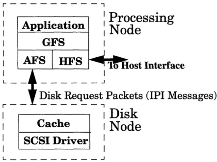
Figure 3.2: Software organization of the Alewife Filesystem.
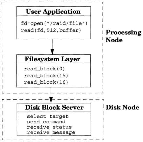
Nodes, PNf. They communicate with the Disk Nodes, DN's, to access blocks of data on the disk drives. Users interact with Alewife through the host interface. Figure 3.2 shows the software structure of the Filesystem. The Filesystem is divided into three parts: the Generic Filesystem, the Alewife Filesystem, and the Host Filesystem. When the user application requests a file operation, the Generic Filesystem (GFS) determines whether the file resides on the disk nodes or on the host computer and passes the request to the appropriate filesystem. The Host Filesystem (HFS) handles files that reside on the host workstation. The Alewife Filesystem (AFS) handles files that reside on the Disk Nodes. These components are described in more detail below. Figure 3.3 shows the logical inter-faces among the user application, the filesystem and the Disk Block Server. When an application running on a Processing Node wants to open a file for read, it makes a call to the filesystem on that node. The filesystem, knowing the high-level layout of the disk, sends a request to the appropriate Disk Block Server for the root directory. Using informa-tion in this directory, the filesystem locates lower-level directories and, eventually, the file
Application
GFS
AFS
.
|HF
I
HFS
I I I Lr - - - -- - - - -- I Processing
I T
I
IN oue I iltI Disk Node
IFigure 3.3: Logical Interfaces of the Alewife Filesystem.
that the application has requested. The i-node, or information-node, of the file is read from the disk and stored locally in memory. It contains information such as length, creation time, permissions, where the file data is located, etc. The filesystem then allocates a "file descriptor" for this file and returns it to the application for later references. Similar steps occur when a file is opened for write; the only difference is that space on the disk is allo-cated for a new directory entry and an i-node. Allocation is done with a remote call to the Disk Block Server where the low-level layout and geometry of the disk is kept.
When the application wants to read data from an already opened file, it again makes a system call to the operating system. The filesystem, using the location information in the i-node of that file, sends read requests to the Disk Block Servers for the file data.
User Application
fd=open("/raid/file") read(fd, 512,buffer)Filesystem Layer
read_block(O) read_block(15) read_block(16)Disk Block Server
select target send command receive status receive message I I I I I I I I I I I I I I I I I I L - - - -I I I I I
The following chapters give detail description of the internal organization and pro-gramming interface of the Alewife Filesystem.
3.2 Application Interface
The user application interface is borrowed largely from Unix. The current implementation supports the following system calls:
* open - open or create a file for reading or writing * close - close a file
* read - read data from disk * write - write data to disk
* fstat - get information on a file or directory * fsync - flush cached data to disk
When a file is opened, the filesystem returns a "file descriptor". This descriptor is later used to identify the file when performing read, write, or close operation. All the above system calls, except write, are blocking. Synopses and descriptions of the functions are given below.
int open(path, flags[ , mode] )
char *path; int flags;
int modes;
open() opens the named file for reading or writing, as specified by the flags argument,
and returns the file descriptor, fd. Path points to the pathname of a file. The flags argument may indicate the file is to be created if it does not already exist (by specifying the O_CREAT flag), in which case the file is created with mode mode for permissions. Other valid flags are O_RDONLY and O_WRONLY for read and write access, respectively. If the O_TRUNC flag is specified with a write operation, the file is truncated to zero length upon opening.
int close(fd)
close deletes the file descriptor, fd. It returns 0 if the operation succeeds. int read(fd, buf, nbyte)
int fd; char *buf;
int nbyte;
read reads nbyte bytes of data from the file and puts it in buf. It returns the number of
bytes actually read from the Disk Nodes. int write(fd, buf, nbyte)
int fd;
char *buf; int nbyte;
write writes nbyte bytes of data from buf to the file. It return the number of bytes
actu-ally written to the Disk Nodes. int fstat(fd, buf)
int fd;
struct stat *buf;
fstat obtains information on a file or directory. It returns the following structure: typedef struct st { int mode; int owner; int last_changed; int size; I stat;
The definition for mode is given in "Locating Files" below. Owner indicates the cre-ator of the file. Last_changed is the most recent date when the file was modified. The for-mat of the data is system-dependent. Size is the length of the file in bytes.
void fsync()
fsync flushes all dirty cache blocks on he Disk Nodes onto the disk drives.
File related library-calls, such as fopen, fread, fwrite, fclose, make use of the system-calls.
3.3 The Filesystem Layer
The Alewife Filesystem is divided into three parts (see Figure 3.2). The Generic Filesys-tem determines whether the file is located on the host or on the Disk Nodes. If the file is located on the host, the Host Filesystem (HFS) takes over. The HFS will not be described in this thesis. If the file resides on the Disk Nodes, control is passed over to the Alewife Filesystem.
3.3.1 The Generic Filesystem
The current implementation is straightforward. Files that are inside the /raid directory are located on the Disk Nodes; all other files are assumed to be on the host.
3.4 The Alewife Filesystem
The filesystem layer of the storage subsystem organizes the raw data on the disks into files and directories. It uses metadata, primarily the i-node, to structure disk information. Free blocks are managed, like the Logical Disk System[10], on the Disk Block Servers. Raw data is transferred in multiples of the transfer size between the filesystem and the Block Servers using Disk Request Packets. The transfer size for this implementation is 1KB.
3.4.2 Locating Files
The Alewife Filesystem uses two metadata items to locate files; they are i-node and directory. An i-node, or information-node, contains a map of where (in what block) the file data is on. Data is always accessed in units of disk block. Blocks are striped across all available disk, when a storage request is large, to increase throughput. Striping is accom-plished by taking the remainder of the block number divided by the number of disks avail-able. Directory structures contain the name of files and lower-level directories. Figure 3.4 shows a sample layout of the file lusr/bin. Since the root (/) i-node is located at a fixed
/usr directory uoot inoae Permissionm Date, etc. page[O] -Root Directory I var usr
Figure 3.4: Example layout of the file /usr/bin.
location on the disk, the Filesystem can use that as the starting point to locate any file within the hierarchy.
Every file (directory included) has an information node, or i-node, which contains the layout, size, permissions, etc. of the file. The following is the type definition for an i-node:
typedef struct inode_entry {
int mode; int owner; int last_changed; int last_accessed; int size; int page_ptr; int n_disks int inode_num; #define NUM_DATA_PAGES 1016 int page[NUM_DATA_PAGES]; } inode_t;
The mode field specifies the type and the permissions for the file. Permissions, like in Unix, exist for the user, the group, and other people. A file can be a data file, a directory, or a symbolic link. The size fields specifies the length of the file in number of bytes. The
Date, etc. page[O]
rr · r r
I--pageptr field specifies how many pages the file occupies and can be derived from size.
Finally, the page array contains pointers to where the actual data of the file is stored. The
n_disk field specifies the number of disks that the file is striped across.
The type definition for a directory entry is given below: typedef struct dir_entry {
unsigned int inode; char filename[124];
} dir_t;
Frequently-used directory paths are cached at the Name Server to speed accesses. The Name Server is the Filesystem Node on the lower left-hand corner of the grid.
3.4.3 Allocating and Freeing Space
A bitmap located on every Disk Server to keep track of the empty blocks. Using the bitmap, the Server allocates free space for the Filesystem when it issues an allocate request. Similarly, a list of blocks is freed by using the free request. Bitmaps are periodi-cally written back to the disks to ensure consistency.
At startup time, the bitmaps are read into main memory. They are written back to disk if the following two conditions are met:
1) it has been ten seconds since the bitmap was last written; 2) the bitmap is dirty.
3.4.4 Communicating with the Disk Block Servers
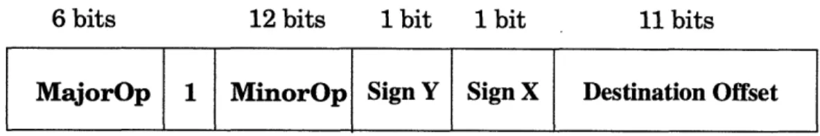
Communications between the Alewife Filesystem and the Disk Block Servers are accomplished using Disk Request Packets. Disk Request Packets are a subset of the Inter-process Interrupt (IPI) packets[13]. On Alewife, the operating system on a node can send an IPI message to another node by using the ipilaunch instruction. When the packet arrives at the remote node, its processor is interrupted and one of many "trap handlers" is dispatched, according to the MajorOp field in packet, to deal with the information. Figure
MajorOp 1 MinorOp Sign Y Sign X Destination Offset
Figure 3.5: Format of a relative IPI packet.
3.5 shows the basic format of a relative IPI packet header. The header is the first word (32 bits) of the packet. The Signs and Destination Offset fields combined specifies the destina-tion relative to the sending node. Absolute addressing cannot be used because the Disk Nodes are on the fifth column (see Figure 3.1) and currently there is a software constraint on where absolute addressing applies. The Alewife Filesystem uses the MinorOp field to specify the operation to be performed at the Block Servers. These operations are:
* read - read a disk block * write - write a disk block
* allocate - allocate blocks for writing * free - free blocks
* get_info - get information about the disk drive
The rest of the packet contains the modifier, the target number, the sequence number, the destination ID, the task number, the block number, and data. Figure 3.6 shows the basic format for Disk Request Packets. The modifier occupies the top byte of the second word. It has the following properties:
Name Description Applies to
Uncache do not cache data Read, Write
Lock exclusive access Read, Write
Table 3.7: Properties of the Modifier field.
The Uncache property reduces cache interference when data is accessed only infrequently. The Lock property is used when the Filesystem on a particular node wants exclusive
M = Modifier
T = Target
I S = Sequence
Write Data
l_ . .
Figure 3.6: Basic format of Disk Request Packets.
access to some data. This is useful when updating metadata. When there are multiple SCSI devices connected to the Disk Node, the Target field indicates which device to operate on. The Sequence field specifies the sub-block number of the write data due to the fact that it takes four packets to fill one block. The Destination ID field specifies the node to which the Disk Response Packet should be sent. When the destination node is not the same as the request node, the request packet is called a proxy request. The thread in the Task field will be woken up after the disk operation is finished. The Block field is the logical block on the disk to be read or written. It also indicates the number of blocks to be allocated for the
allocate request. The Request ID field is used to keep track of out-of-order requests.
3.4.5 Startup Initialization
At startup time, the master Disk Block Server-the Server on the lower left-hand corner of the grid, if it exists, or the one on the upper right-hand corner-detects how many disks are present by broadcasting requests to all the Disk Nodes. It then communicates this data
Header
M T S
DestID
Task
Block
Request ID
to the Filesystem Nodes. The Filesystem Nodes, using this information, compute headers for communicating with the Disk Block Servers.
The free bitmaps are also read into memory at startup time for storage allocation oper-ations. These bitmaps are located at the beginning to the disk; each bit in the bitmap repre-sents a 4K block on the disk. For a 1 GB disk, only 32 KB of space is needed for the bitmap.
3.5 Disk Block Server
The Disk Block Server, or Disk Node, presents the filesystem-layer a device-indepen-dent interface to the storage device. The Server program executes on the Disk Interface Board (see "Hardware") and accepts requests from the Filesystem Nodes over the net-work. It performs all low-level interactions with the disk drive and caches data to improve performance. In terms of the filesystem hierarchy described in the "Overview" chapter, the Disk Node contains the device-driver and the middle-layer. Figure 3.8 shows the inter-nal components and data flow of the Disk Block Server. The IPI Message-In Handler is an interrupt-driven routine that accepts disk block requests from the Filesystem Nodes over the network. The Cache Module stores frequently-used data to improve performance. The SCSI Driver interfaces with the disk drive. In the where the requested data is cached, pro-gram execution bypasses the SCSI Driver and the data is sent back to the requester imme-diately. The IPI Message-Out Handler sends acknowledgments and data back to the requesters. The following subsections describe these components in greater detail.
3.5.6 IPI Message-In Handler
The Message-In Handler accepts messages from the Filesystem Nodes and queues up the requests onto the job queue for later processing. If the data requested is in the cache, it
Network In
Network Out
* t
Figure 3.8: Internal data flow of the Disk Block Server.
is immediately sent back to the requester. When a disk block request comes in, an I/O Request (IOR) structure is allocated to store the message. The IOR type definition is:
typedef struct io_req { struct io_req *next; int opcode; int modifier; int dest_id; int task; int block; int sequence; int io_count; cache_block_t *buffer; unsigned char status; unsigned char target;
void (*continuation)(struct io_req *) io_req_t;
The opcode, modifier, dest_id, target, sequence, task and block are copied from the Disk Request Packet when it is received. Buffer points to an entry in the cache where the disk block is. When there are multiple requests pending on a cache location, next points to the next waiting IOR. Since the block size is four times that of the transfer size, four separate
IPI Message-In
Handler
IIPI Message-Out
Handler
Cache IModule
SCSI
Driver
- · I ·IC I l ! | 0 i I 1 -... a _-G t:l ~~ CI·~~owDisk Block Requests (and IOR) are needed to complete a write. The following paragraphs describe the program flow after requests have been accepted.
After an IOR has been constructed for a read request, the cache is searched for the block. If the data happens to reside in the cache, the IOR, together with the cache block, is forwarded to the IPI Message-Out Handler. If the cache block does not exist, a new cache block is allocated and, together with the IOR, is queued up for processing at the SCSI Driver. The queue uses the "Elevator Algorithm" where blocks are sorted in ascending order to minimize seek time. If the cache block exists but is being written to, the IOR is queued up as a waiter for the block; data will be sent out as soon as the write completes. Read requests has higher priority over writes. The following paragraph describes the pro-gram flow for a write request.
After an IOR has been constructed for a write request, the cache is searched for the block. A new cache entry is allocated for the block if it does not exist already. Write data from the packet is stored into one of four segments in the cache block. Read access to a block with write pending is queued up. The result of a write operation during a pending-read is unpredictable.
3.5.7 Cache Module
The Cache Module speeds accesses by storing frequently-used data in memory. The block size of the cache is 4 KB, the total cache size is 2.5 MB, and the replacement strat-egy is Least-Recently-Used (LRU).
When a read request comes in, the cache is first searched for the block. If it exists in the cache, data is forwarded directly to the IPI Message-Out Handler without going through the disk driver. When a write request comes in, the data is stored directly into the cache and the request is queued for processing at low priority.
3.5.8 SCSI Driver
The SCSI Driver controls the hard disk connected to the Disk Interface Board by translating read and requests into the low-level SCSI protocol. The Driver is interrupt-driven; it is executed when the job queue, managed by the IPI Message-In Handler, is full. The low-level SCSI protocol is described in the "SCSI Controller Chip" subsection in the "Hardware" chapter.
3.5.9 IPI Message-Out Handler
The IPI Message-Out Handler is responsible for sending acknowledgments and read data back to the requesters. In the case of multiple pending reads, the handler follows the list of waiters in the cache block and sends the data out sequentially.
3.6 Summary
The Alewife Secondary Storage Subsystem software implements a Unix-like filesystem. The execution of the Alewife Filesystem is distributed throughout the machine to enhance performance and scalability. Made possible by the low-latency network, the Storage Sub-system uses a fine-grain client-server model. The Alewife FileSub-system is responsible for locating files and directories on the disks. The Disk Block Servers control the disk drives and transfer blocks of data between the disk and the Filesystem.
Chapter 4: Hardware
This chapter describes the hardware portion of the Alewife Secondary Storage Subsystem. The hardware subsystem consists of one or more Disk Nodes and zero or more I/O Nodes. Each Disk Node consists of a disk drive interface board and one or more hard disk drives (see Figure 4.1). The Disk Node transfers data between the disk drives and the rest of the Alewife system. The I/O Nodes controls the layout and organization of the filesystem stored on the disk drives. As discussed in the previous chapter, the I/O nodes are normal Processing Nodes executing the filesystem software. The implementation in this thesis integrates the I/O Node with the Processing Node to reduce latency. The whole system is connected by a high-speed mesh network with transfer rate of up to 100MB/s per chan-nel[2].
The two most important design considerations for the Alewife Storage Subsystem are flexibility and scalability. To support the idea of a framework for storage architecture research, the hardware must be flexible enough to allow reconfiguration. For the same
rea-Disk Interface Board
-, / Disk Drives DN
J
IN-...
~~
. . . I-, ,* * *A Disk NodePN
P(~~
...
-Q~
'
PN:
Processing
Node
Alewife Multiprocessor DN: Disk Node I/O: I/O Node
son, the hardware must be scalable to allow experiments of realistic size to be performed. Based on these two criteria, the Disk Interface Board has been built on top of the existing Alewife Processing Node to allow the use of the scalable multiprocessing capability inher-ent in the system. More importantly, Alewife is the only multiprocessor that supports both the distributed shared-memory and the message-passing paradigms. Storage architectures based on these two paradigms together have not been previously studied.
The Disk Interface Board communicates with the disk drives using the Small Com-puter Systems Interface, or SCSI[1]. Virtually all workstations now have SCSI disk drives, tape drives, etc. Using a widely accepted industry standard guarantees ample and inexpen-sive supply of disk drives from multiple vendors. More importantly, it makes the system expandable; the Disk Node can communicate with a plethora of storage devices that com-ply with the SCSI standard.
The following sections describes the disk interface board hardware in detail.
4.1 Disk Interface Board
The design is a modification of the original Alewife Processing Node. The interface board contains all the components of the original node board with the exception of the Floating-Point Unit. The FPU was removed to make room for the disk controller circuitry. Through extensive use of surface-mount technology, the disk interface board achieves the same form-factor as the Processing Node. Figure 4.2 shows the block diagram of the disk inter-face board. The components outside the dotted box represent additions to the Processing Node. The DMA FIFO (Direct Memory Access First-In-First-Out) buffers data between the SCSI controller chip and the central processing unit, SPARCLE. It also contains inter-face circuitry to communicate with the controller chip. The SCSI controller chip imple-ments some of the interface specification in hardware and thus free SPARCLE from
r
I I I I I I I I I I I L - - - JFigure 4.2: Block diagram of the Alewife Disk Interface Board.
performing low-level control of the disk drives.
4.1.1 DMA FIFO
The DMA FIFO, IDT 72520[8], serves as a buffer and an interface between the SCSI controller chip and SPARCLE. Data is temporarily stored in the DMA FIFO to reduce the load on SPARCLE. More significantly, the FIFO makes up for the lack of DMA circuitry in the current version of the Alewife Cache Memory Management Unit (CMMU)[13]. Using direct memory access approximately speeds data transfer by a factor of five. Another important feature of the FIFO is the "bypass" path; it allows direct communica-tion between the SPARCLE processor and the SCSI controller chip. This feature is utilized when accessing the control registers on the SCSI chip.
4.1.2 SCSI Controller Chip
The SCSI Controller Chip, NCR53CF94-2[15], implements some of the interface specification in hardware to reduce the workload on SPARCLE. The SCSI protocol speci-fies seven phases of operation-Bus Free, Arbitration, Selection, Command, Data Transfer, Message, and Status. A SCSI transaction is composed of several of these phases. For example, when the Disk Interface Board (called the initiator in SCSI terminology) wants
to communicate with the disk drive (called the target), it first listens to the bus to make sure that the bus is free. Then it arbitrates for the SCSI bus by asserting its ID on the bus. If more than one device arbitrate for the bus at the same time, the one with higher ID num-ber wins. After the initiator has won arbitration, it transfers a Command Description Block (CDB) over to the target during Command phase. The CDB is usually six, ten, or twelve bytes long and contains the operation that the initiator wants to be performed. If data trans-ferred is needed to complete the transaction, the target goes to Data In or Data Out phase, depending on the direction of the transfer. Data is transferred over the SCSI bus and the target changes to Status phase. If the command has been successfully executed, the target sends the "Command Complete" status to the initiator; otherwise, the "Check Condition" is sent. Finally, the target sends a "Disconnect" during the Message phase and disconnects from the bus. The bus returns to Bus Free phase.
4.2 Disk Drives
Each Disk Interface Board is connected to an IBM 0662 disk drive. Table 4.1 gives a sum-mary of the technical specifications[9]. The IBM disk has a formatted capacity of 1.05 gigabytes and an average seek time of 8.8 ms. The seek time is based on weighted average of 4 reads and 1 write. A similar drive, the Seagate ST32100N, was also considered. The IBM drive was chosen for its superior reliability and performance. It has a Mean-Time-Between-Failure (MTBF) of 800,000 hours, compared to 500,000 hours for Seagate. More importantly, even though the Seagate drive has, on paper, similar seek time and transfer rate, the IBM drive performs better in actual tests.
Capacity 1,052,175,360 Bytes
Average Seek Time 8.8 ms Media Transfer Rate 5-6 MB/s
Capacity 1,052,175,360 Bytes
Buffer Size 512 KB
Power Consumption 10.55 W
MTBF 800,000 hours
Chapter 5: Performance and Conclusion
This chapter presents some experimental and analytical results of the Alewife Secondary Storage Subsystem. The experiments are performed on a four-node Alewife Multiproces-sor (see Figure 5.1).
Figure 5.1: Setup of the Storage Subsystem for experimentation.
The Alewife Filesystem System software has not been optimized for speed. The cur-rent implementation sacrifices some performance for flexibility. With the Alewife Filesys-tem, there is no limitation on the number of Disk Nodes; the filesystem configures itself at startup time. Furthermore, data is striped, automatically, across all available disks to enhance performance.
5.1 Single Client Results
In these experiments, one processor node makes read and write requests to the Disk Block Servers. Figure 5.2 shows the results for cached-read. The maximum throughput is about 4.5MB/s. The latency can be estimated from the data points for 1000-, 2000-, and 4000-byte reads since they all read a minimum block size of 4096 4000-bytes. After the overhead has been accounted for, the estimated latency for a cached-read is 25,000 cycles. With a pro-cessor speed of 20 MHz, the latency comes out to be about 1.25ms. The routine that copies data from the I/O buffer to the user buffer, bcopy, turns out to be a significant overhead. Each byte takes about 2 cycles to be copied. If data were copied directly into the user
One-Processor Cached-Read Performance
0- I-1 I I I I I 2 4 5 10 50Block Size (Thousands of Bytes)
Figure 5.2: Single-processor cached-read results.
buffer, the cached-read bandwidth would have been 8 MB/s (see Figure 5.3). In the current implementation, data is not copied directly into the user-space due to the fact that the des-tination locations can be globally-shared; using the CMMU to copy into global memory is very complicated.
Figure 5.4 shows the results for write throughput versus block size. All writes are buff-ered at the cache and are non-blocking. The peak throughput is 5.3 MB/s at a block size of 2000 bytes. This higher-than-expected result can be attributed to the non-blocking nature
Figure 5.3: Improving cached-read performance
Improving Cached-Read PerformanceI
v
.-0)
-1 Z 4 5 10 50 100 200 400 500 1000 Block Size (Thousands of Bytes)
II- -1
III 1 1 iii iiiiiiiiiiiiiiiiiiililill
Baseline El No Copy 100 200
One-Processor Write Performance
-T 5-M 4-a 3-c, 2- 2-- 1-r I I __ 2 4 5 10 50Block Size (Thousands of Bytes)
100 200
Figure 5.4: Single-processor write results.
of writes. The sustained maximum throughput is 4.3 MB/s. Again, bcopy incurs signifi-cant overhead. If data were sent directly from the user buffer, the throughput would have been 7.6 MB/s.
Figure 5.5 shows the results for uncached-reads versus block size. The experiment mainly shows the efficiency of the SCSI Device Driver. The sustained peak performance is about 1.3 MB/s. The dip at 5000 byes is due to the fact that transfers are always done in blocks of 4096 bytes; a 5000-byte request requires the overhead of fetching a second
One-Processor
Uncached-Read
Performance
4r E 1-Co 0. M 0.5-0 - i--i I I I I 2 4 5 10 50
Block Size (Thousands of Bytes)
100 200
1 00 200
Figure 5.5: Single-processor uncached-read results.
1 400 c 1 1 400 l .. r I -El ·
Improving Uncached-Read Performance
=~~~~~~~~~~~~~~~~~~~--
---i" 2 I-1 4 10 100 400 1000 2 5 50 200 500
Block Size (Thousands of Bytes)
I
Baseline
1El No Copy El CMMU DMAFigure 5.6: Improving uncached-read performance.
block. Again, if data were copied directly into the user buffer and if the CMMU could DMA directly from the disk to the cache, the throughput would have been 1.7 MB/s (see Figure 5.6). The estimated latency for an uncached-read is 67000 cycles. With a processor speed of 20 MHz, the latency is about 3.4 ms. This estimate does not include seek time of the disk drive.
Figure 5.7: Cycle breakdown by operations.
Cycle Breakdown
Of%~ ou 70 60 Cb 50 , , 40 - 30 20 10 0Uncached Read Cached Read
Access Type
[-7 Cache
A Disk Transfer
[IIIII Disk Support
* Launch El Filesystem
Figure 5.7 is a breakdown, by operations, of the cycles spent during cached- and uncached reads of a 1000-byte block. Disk cache operations (labeled Cache in the graph), such as allocating and searching for entries, take 1% or less of the total cycle time and are not visible in the graph. Data transfer from the SCSI disk to the cache (Disk Transfer), uses 49%of the uncached-read cycle time. Setting up the disk transfer (Disk Support) uses 14% of the cycle time. Launching the data for uncached- and cached-reads take 2% and 5%, respectively, of the cycle time. The filesystem on the client-side takes 45% and 97% of the cycle time for, respectively, uncached- and cached-reads. Figure 5.8 shows the cycle breakdown of a read access that requires a half-stroke seek in addition to the operations shown in Figure 5.7. The seek, going from outermost track to the middle of the disk, takes 11.5 ms, or 83% of the server time, to finish. This result is consistent with the specification of the drive..
Figure 5.8: Cycle breakdown with seek.
300
o
0'0
0 :1000
Uncached Read Seek Cached Read Access Type L. Cl Cache I Disk Transfer E Disk Seek * Disk Support * Launch L Filesystem
Cycle Breakdown with See
F
Figure 5.9: Two-processor cached-read results.
5.2 Two-Client Results
In this experiment, two processors request reads from the same file from the Disk Block Servers. Figure 5.9 shows the results. These are almost identical to the single-processor results. This indicates that the Disk Block Server are still far from saturation when two processors are requesting cached data at the same time.
5.3 Conclusion
A complete secondary storage subsystem, including both hardware and software, has been constructed for the Alewife Multiprocessor. The Alewife Filesystem-a filesystem imple-mentation using the Alewife Secondary Storage Subsystem-combines several ideas from existing parallel disk systems. It uses block-servers, RAID-like striping, distributed file-system, and multiple network connections to enhance performance and scalability. The Filesystem also demonstrates the versatility and performance of the Alewife Multiproces-sor. With the capabilities and flexibility inherent in the architecture, the Alewife Second-ary Storage Subsystem is an ideal platform for storage system research.
Two-Processor Cached-Read Performance
5- 4-2
0 5
1 2 4Block 5 10 50 Bytes) 10 20 400of Block Size (Thousands of Bytes)
Bibliography
[1] American National Standard, Small Computer System Interface (SCSI), American National Standard, New York, New York, 1986.
[2] Anant Agarwal, David Chaiken, Godfrey D'Souza, Kirk Johnson, David Kranz, John Kubiatowicz, Kiyoshi Kurihara, Beng-Hong Lim, Gino Maa, Dan Nussbaum, Mike Parkin and Donald Yeung, "The MIT Alewife Machine: A Large-Scale Distributed-Memory Multiprocessor", Proceedings of Workshop on Scalable Shared Distributed-Memory
Mul-tiprocessors, Kluwer Academic Publishers, 1991.
[3] Pei Cao, Swee Boon Lim, Shivakumar Venkataraman and John Wilkes, "The Ticker-TAIP parallel RAID architecture," Proceedings of the 20th Annual International
Sym-posium of Computer Architecture, pp. 52-63, May 1993.
[4] David Chaiken, John Kubiatowicz and Anant Agarwal, "LimitLESS Directories: A Scalable Cache Coherence Scheme," Fourth International Conference on
Architec-tural Support for Programming Languages and Operating Systems (ASPLOS IV),
ACM, pp. 224-234, April, 1991.
[5] Ann L. Chervenak, "Performance Measurements of the First RAID Prototype," Tech-nical Report UCB/CSD 90/574, University of California, Berkeley, May 1990.
[6] Garth Alan Gibson, "Redundant disk arrays: reliable, parallel secondary storage," UCB/CSD 91/613 (Ph.D thesis), University of California, Berkeley, December 1990. [7] John H. Hartman, John K. Ousterhout, "Zebra: a striped network file system,"
Techni-cal Report UCB/CSD 92/683, University of California, Berkeley, April 1992.
[8] Integrated Device Technology, Specialty Memory Data Book, Integrated Device Tech-nology, San Jose, California, 1993.
[9] International Business Machines Storage Division, Functional Specification 0662
Models S12,SlD,SW1,SWD 1.05 GB - SCSI - 3.5 Inch Drive Release 2.1, International
Business Machines, San Jose, California, April, 1993.
[10] Wiebren de Jonge, M. Frans Kaashoek and Wilson C. Hsieh, "Logical disk: a simple new approach to improving file system performance," Technical Report MIT/LCS/ TR-566, MIT Laboratory for Computer Science, Cambridge, Massachusetts, April
1993.
[11] R.H. Katz, P.M. Chen, A.L. Drapeau, E.K. Lee, K. Lutz, E.L. Miller, S. Seshan, D.A. Patterson, "RAID-II: Design and Implementation of a Large Scale Disk Array Con-troller," Technical Report UCB/CSD-92-705, University of California, Berkeley, October 1992.
[12] David Kotz, "Multiprocessor File System Interfaces," Technical Report PCS-TR92-179 (revised), Dartmouth College, Hanover, New Hampshire, 1992.
[13] John Kubiatowicz, "Users Manual for the Alewife 1000 Controller," Alewife Sys-tems Memo #19, MIT Laboratory for Computer Science, Cambridge, Massachusetts,
1991.
[14] Edward K. Lee, Peter M. Chen, John H. Hartman, John H. Drapeau, Ann L. Cherve-nak, Ethan L. Miller, Randy H. Katz, Garth A. Gibson, David A. Patterson, "RAID-II:
a scalable storage architecture for high-bandwidth network file service," Technical Report UCB/CSD 92/672, University of California, Berkeley, February, 1992.
[15] NCR Corporation, 53CF94/96-2 Fast SCSI Controller Data Manual, NCR Micro-electronics Division, Dayton, Ohio, 1993.
[16] David A. Patterson, Garth Gibson and Randy Katz, "A Case for Redundant Arrays of Inexpensive Disks (RAID)," Proceedings of the International Conference on
Manage-ment of Data, pp. 109-116, Chicago, Illinois, June 1988.
[17] R. Rodriguez, M. Koehler, and R. Hyde, "The Generic File System," Proceedings of
the Summer 1986 USENIX Conference, pp. 260-269, Atlanta, Georgia, June, 1986.
[18] Russel Sandberg, David Goldberg, Steve Kleiman, Dan Walsh, and Bob Lyon, "Design and Implementation of the Sun Network filesystem," Proceedings of the
Sum-mer 1985 USENIX Conference, pp. 119-130, Portland, Oregon, June, 1985.
[19] Avidas Tevanian and Richard F. Rashid, "MACH: a basis for future UNIX develop-ment," Technical Report CMU-CS-87-139, Carnegie-Mellon University, Pittsburgh, PA, June 1987.