https://doi.org/10.4224/23003983
READ THESE TERMS AND CONDITIONS CAREFULLY BEFORE USING THIS WEBSITE. https://nrc-publications.canada.ca/eng/copyright
Vous avez des questions? Nous pouvons vous aider. Pour communiquer directement avec un auteur, consultez la première page de la revue dans laquelle son article a été publié afin de trouver ses coordonnées. Si vous n’arrivez pas à les repérer, communiquez avec nous à [email protected].
Questions? Contact the NRC Publications Archive team at
[email protected]. If you wish to email the authors directly, please see the first page of the publication for their contact information.
Archives des publications du CNRC
For the publisher’s version, please access the DOI link below./ Pour consulter la version de l’éditeur, utilisez le lien DOI ci-dessous.
Access and use of this website and the material on it are subject to the Terms and Conditions set forth at
Guideline on design for durability of building envelopes
Lacasse, Michael A.; Ge, Hua; Hegel, Mark; Jutras, Robert; Laouadi, Aziz;
Sturgeon, Gary; Wells, John
https://publications-cnrc.canada.ca/fra/droits
L’accès à ce site Web et l’utilisation de son contenu sont assujettis aux conditions présentées dans le site LISEZ CES CONDITIONS ATTENTIVEMENT AVANT D’UTILISER CE SITE WEB.
NRC Publications Record / Notice d'Archives des publications de CNRC:
https://nrc-publications.canada.ca/eng/view/object/?id=45b6a70c-e5a7-419a-bb1a-4687435c7895 https://publications-cnrc.canada.ca/fra/voir/objet/?id=45b6a70c-e5a7-419a-bb1a-4687435c7895
Guide line on De sign for Dura bilit y of
Building Enve lope s
Michael A. Lacasse, Hua Ge, Mark Hegel, Robert Jutras,
Aziz Laouadi, Gary Sturgeon and John Wells
Report: CRBCPI-Y2-R19
12-April-2018
Guideline on Design for Durability of
Building Envelopes
Author
Dr. Michael A. Lacasse, P. Eng.
Approved
Philip Rizcallah, P. Eng. Program Leader
Building Regulations for Market Access NRC Construction Research Centre
Client Report: CRBCPI-Y2-R19
Report Date:
12 April, 2018
Contract No:
A1-012020-04
Reference:
29 November 2016
Program:
Building Regulations for Market Access
35 pages Copy no. 5 of 5
This report may not be reproduced in whole or in part without the written consent of the National Research Council Canada and the Client.
April
2018
Guideline on Design for Durability of
Building Envelopes
12 April 2018
This document has been prepared for consideration by committees dealing with the National Building Code of Canada. The views expressed in this paper are those of the authors and do not represent those of the Canadian Commission on Building and Fire Codes or of the Construction Research Centre. This Guide has
Page i of vi
T a ble of Cont e nt s
Table of Contents ... ..i
Task Group — Guideline on Design for Durability of Building Envelopes ...iv
Forward ... .vi
1. Background information ... 1
2. Scope ... 2
3. Normative References ... 4
3.1 General ... 4
3.2 Material property characterization ... 5
3.3 Wall system specifications ... 6
3.4 Climate loads ... 6
4. Definitions, Abbreviations, Symbols and Units ... 7
4.1. Definitions on design of structures for durability ... 7
4.1. Definitions on design of structures for durability, cont’d ... 8
4.2 Abbreviations... 9
4.3 Symbols and Units ... 9
5. Design approach (ISO 13832)... 10
5.1 Introduction ... 10
5.2 Design for durability of wall assemblies ... 12
5.2.1 Introduction ... 12
5.2.2 Evaluation procedure ... 17
6. Procedures ... 19
6.1 Design Service Life ... 19
6.2 Hygrothermal simulation tools ... 19
6.3 Material properties ... 19
7. Boundary conditions ... 21
7.1 Exterior boundary conditions ... 21
7.2 Interior boundary conditions... 21
8. Documentation ... 22
8.1 General ... 22
8.2 Problem description ... 22
8.2.1 General ... 22
8.2.2 Scope and subject of simulation ... 22
8.2.3 Initial conditions ... 22
Page ii of vi
8.2.5 Material parameters ... 22
8.2.6 Mesh geometric configuration and related details ... 23
8.3 Hygrothermal model and numerical solution ... 23
8.3.1 General ... 23 8.3.2 Simulation tool ... 23 8.3.3 Numerical simulation ... 23 9. Performance evaluations ... 24 10. Reporting... 25 10.1 Display of results ... 25 10.2 Interpretation of results ... 25 Bibliography ... 26 Annex A ... 28
Performance evaluation process for wood-based wall components and assemblies... 28
A.1 Performance attributes ... 28
A.2 Performance criteria ... 28
A.3 Performance evaluation process ... 28
Annex B ... 29
Performance evaluation process for reinforced concrete and un-reinforced concrete ... 29
B.1 Notional performance attributes ... 29
B.2 Notional performance criteria ... 30
B.3 Performance evaluation process ... 30
Annex C ... 31
Performance evaluation process for concrete block masonry and structural brick masonry ... 31
C.1 Performance attributes ... 31
C.2 Performance criteria ... 31
C.3 Performance evaluation process ... 31
Annex D ... 32
Performance evaluation process for light-weight gauge steel elements ... 32
D.1 Notional performance attributes ... 32
D.2 Notional performance criteria ... 32
D.3 Performance evaluation process ... 32
D.3.1 Evaluation process ... 32
D.3.2 ISOCORRAG method ... 33
Annex E ... 34
Performance evaluation process for metal fasteners, ties, anchors, connectors and lath ... 34
E.1 Notional performance attributes ... 34
E.2 Notional performance criteria ... 34
Page iii of vi
T a sk Group — Guide line on De sign for Dura bilit y of
Building Enve lope s
Michael A. Lacasse National Research Council of Canada, Ottawa, Ontario Group lead Hua Ge Concordia University, Montreal, Quebec Member Mark Hegel Alberta Masonry Council, Calgary, Alberta Member Robert Jutras CLEB, Varennes, Quebec Member Aziz Laouadi National Research Council of Canada, Ottawa, Ontario Member Gary Sturgeon BBSTEK Design Ltd. Millarville, Alberta Member John Wells Crosier Kilgour & Partners, Winnipeg, Manitoba Member
Page v of vi
Forw a rd
This document provides guidance on the use of heat, air and moisture transfer (hereinafter referred to as hygrothermal) models to provide results from which to infer the durability of building elements, which include building envelope materials, components and assemblies in opaque wall systems. It is intended for use by expert practitioners who have knowledge of the use of hygrothermal models to provide results used to inform on the resilience of envelope design; have an understanding of the principles of applied building physics and are familiar with the durability of building materials, components and assemblies. Hygrothermal modelling is used to evaluate the short‐ and long‐term thermal and moisture performance behaviour of building envelopes. A hygrothermal model is a mathematical representation of the equations that govern the heat, air and moisture transfer that occurs in components of a user defined configuration of a specific building envelope assembly subjected to heat and moisture loads. Hygrothermal modelling is a useful tool that can provide a ready means of estimating what temperature and moisture conditions prevail in given components of an envelope assembly when the assembly is subjected to simulated conditions of climate on the exterior of the assembly and indoor conditions within the interior. In this document, the standards to be consulted are specified for: • Designing for durability of building elements within the building envelope; • Undertaking hygrothermal simulations; • Ensuring that material properties used as input to the hygrothermal model are consistent with requirements for calculating the non‐steady state transfer of heat, air and moisture transfer through building structures, and; • Identifying boundary conditions to which the envelope is subjected on the exterior as well as the interior of the assembly. The document can be used for new wall systems or for assessing the durability of retrofits. Although fenestration components can form part of wall assemblies, the durability of the fenestration components and assemblies themselves are not considered in this guide. However, the openings in which the fenestration components are installed can be modelled and are thus part of the guide. Similarly, through‐wall penetrations, such as a ventilation duct, pipe, electrical conduit, or electrical outlet are component details that can be modelled and form part of this guide. The types of building envelope systems that are addressed in this document include, but are not limited to: (i) Whole or in part of institutional, commercial and industrial (ICI) buildings and multiple urban residential buildings • Masonry veneer / steel stud wall systems • Masonry veneer / concrete block masonry wall systemsPage vi of vi • Masonry veneer / concrete wall systems • Masonry veneer / wood structural wall systems • Brick masonry structures (conventional and historic) • Concrete and precast concrete wall elements • External Thermal Insulation Composite System (ETICS) and Exterior Insulation Finish System (EIFS) • Metal‐glass curtain wall and window‐wall systems (ii) As may form part of housing and small buildings (NBC Part 9 buildings) • Wood frame structures having different types of cladding • Light‐weight steel frame structures having different types of cladding Information is also given on the minimum requirements for documentation of data input. Detailed information is provided on performance evaluations of different types of wall systems. Also provided in this document are examples that are intended to be used for validating simulation methods claiming conformity with this guideline, together with the allowed tolerances. This document is focused on building envelope systems forming a wall; subsequent editions are to consider the design for durability of roofs, junctions and that form a portion of the envelope below grade. DISCLAIMER
No liabilit y for t he cont ent of t his docum ent is assum ed by t he aut hors. Ev ery reasonable effort has been m ade t o ensur e t hat t he cont ent of t his docum ent is up t o dat e and is accurat e and
com plet e. Nev ert heless, t he occurrence of errors cannot be ent irely discount ed and t he user assum es all r isk in t he int erpret at ion and im plem ent at ion of t he inform at ion in t his docum ent . The
onus rem ains on t he user t o validat e t he assum pt ions, result s and conclusion draw n from t he use of t his docum ent . No w arrant y is given in respect of t he t im eliness, accuracy or com plet eness of
m at er ial published in t his docum ent and t he aut hors disclaim all liabilit y for loss or dam age incurr ed by t hir d part ies ar ising from t he use of t he cont ent s of t his docum ent .
Page 1 of 34
1 . Ba c k ground inform a t ion
The purpose of this document is to provide information on evaluating the durability of building elements, which include building envelope materials, components and assemblies based on the results derived from the response of a hygrothermal simulation tool when the envelope, as configured in the simulation tool, is subjected to the anticipated thermal and moisture loads. The durability is to be based on anticipated effects arising from the presence of internal and exterior thermal effects and moisture on or in wall assemblies when they are subjected to thermal and moisture loads. The moisture loads of specific interest are those that may arise due to wind‐driven rain and the presence of condensation on the surfaces of critical materials and components of the envelope assembly for any given geographical location of interest to the user and for which climatological data are available. It is assumed that these moisture loads will give rise to environmental actions that in turn will initiate and thereafter propagate the degradation effects on components of the wall system. The approach adopted for assessing the durability of building envelope materials, components and assemblies is provided in standard ISO 13823 ‐ General principles on the design of structures for durability [11]. Predetermined moisture loads on the wall exterior surface as arise from rainfall are to be derived from knowledge of yearly climate loads where a series of at least ten (10) years can be classified in terms of severity by year and from which return periods can be calculated. As such, moisture load reference years for any given location can be determined and the wall subjected to a specific predetermined moisture load. In a similar fashion, reference years to determine the risk to formation of condensation in wall assemblies can also be addressed noting that the reference year would be extracted from those years having experienced extreme cold. The process for evaluating the durability of the envelope system is described for several different types of wall assemblies including those used in industrial, commercial and institutional buildings and multiple urban residential buildings. These wall assemblies include cast‐in‐place concrete and precast concrete panels, brick and concrete block masonry walls, brick veneer walls, Exterior Insulated Finish Systems (EIFS), and External Thermal Insulation Composite System (ETICS) as well as those used for housing and small buildings (i.e. wood and light gauge steel frame structures incorporating different cladding types). The process of evaluation as described in this document permits predicting the short‐ and long‐ term durability of wall assemblies when subjected to local moisture and thermal loads and which can be used for the purpose of, for example, completing a life cycle analysis of a wall structure, declaring a service life, as part of an EOTA (European Organisation for Technical Approvals) environmental declaration, formulating a maintenance management plan for a building and for assessing the effects of anticipated changes to the resilience of an envelope assembly as a result of climate change.
Page 2 of 34
2 . Sc ope
This document provides guidance on the use of hygrothermal models to provide results from which to infer the durability of building envelope materials, components and assemblies (i.e. building elements); specifically opaque wall assemblies. It specifies the standards to be consulted for: • Designing for durability of building envelope materials, components and assemblies; • Undertaking hygrothermal simulations; • Ensuring that material properties used as input to the hygrothermal model are consistent with requirements for calculating the non‐steady state transfer of heat, air and moisture through building structures, and; • Identifying environmental boundary conditions to which the envelope is subjected, e.g., on the exterior and interior of a wall. The building envelope wall assemblies addressed in this document include, but are not limited to: (i) Industrial, commercial and institutional buildings and multiple urban residential buildings having the following nominal set of structural and cladding systems • Structural Systems o Concrete block masonry, both loadbearing and non‐loadbearing infill o Masonry structures, conventional (i.e. brick, stone, terra‐coat cotta, concrete block) [37], [38] o Masonry structures, both new and historic o Cast‐in‐place and precast concrete [41], [42] o Wood frame structural systems, both loadbearing and non‐loadbearing infill o Light‐weight steel frame structural systems, both loadbearing and non‐ loadbearing infill o Pre‐engineered steel building systems • Cladding Systems: o Adhered thin masonry veneer (thin brick, thin natural and manufactured stone) o Fibre cement‐based siding o Exterior Insulation Finish System (EIFS) [30] o External Thermal Insulation Composite System (ETICS) [43], [44] o Full bed masonry (clay/concrete/calcium silicate brick, architectural concrete block, natural stone, terra cotta) veneer o Metal siding and metal insulated composite cladding o Metal‐glass curtain wall and window‐wall systems (ii) Housing and small buildings having the following sets of structural and cladding systems: • Structural Systems: o Wood frame structural systems having different types of cladding systems o Light‐weight steel frame structural systems having different types of cladding systemsPage 3 of 34 o Other structural systems also used in housing and small buildings identified for ICI construction, above • Cladding Systems o Full bed masonry veneer, metal siding, vinyl siding, cement‐based siding, wood siding, EIFS and adhered thin masonry veneer Information is also given on the minimum requirements for documentation of data input. Detailed information is provided on performance evaluations of different types of wall assemblies. The design approach to be used for evaluating the durability of building elements in wall assemblies is defined in § 5 of this document. The procedures for undertaking a hygrothermal simulation are given in § 6 whereas the methods used to define the boundary conditions for the simulation are given in § 7. In § 8 the requirements for documenting the input data and process of simulation are described. Thereafter, in § 9 the process for evaluating the durability of wall assemblies is described. The final section, § 10, is focused on reporting the results (i.e. identifying what should be provided as a minimum) and recommended guidelines for the interpretation of results. A bibliography of pertinent information is provided at the end of the document.
Page 4 of 34
3 . N orm a t ive Re fe re nc e s
3 .1 Ge ne ra l [1] ANSI/ASHRAE 160‐2009 Criteria for Moisture‐Control Design Analysis in Buildings [2] ASTM E3054/E3054M − 16 Standard Guide for Characterization and Use of Hygrothermal Models for Moisture Control Design in Building Envelopes; American Society for Testing and Materials, West Conshohocken, PA, USA; DOI: 10.1520/E3054_E3054M‐16 [3] Bomberg, M. T. and Kumaran, M. K. (1986), A Test method to determine air flow resistance of exterior membranes and sheathings, Journal of Thermal Insulation, Vol. 9 (Jan.). pp. 224–235; NRC 35483 [4] British Standard, BS 7543:2015, Guide to durability of buildings and building elements, products and components. [5] Carmeliet, J. and Roels, S. (2002), Determination of the moisture capacity of porous building materials, Volume: 25 issue: 3, page(s): 209‐237 ; January 1, 2002 [6] CSA O86.1‐14 − Engineering design in wood, CSA Group, Toronto; 240 pgs. [7] CSA S478‐95 (R2007) − Guideline on Durability in Buildings; CSA Group, Toronto; 93 pgs. [8] EN 15026:2007‐07 – Hygrothermal performance of building components and building elements – Assessment of moisture transfer by numerical simulation [9] ISO 2394:1998 − General principles on reliability for structures [10] ISO 9346:2007 − Hygrothermal performance of buildings and building materials ‐‐ Physical quantities for mass transfer – Vocabulary [11] ISO 13823:2008 − General principles on the design of structures for durability [12] ISO 15686 − Buildings and constructed assets ‐ Service life planning [13] ISO 16204:2012 ― Durability — Service life design of concrete structures [14] EN / ISO 15927‐3 − Hygrothermal performance of buildings − Calculation and presentation of climatic data − Part 3: Calculation of a driving rain index for vertical surfaces from hourly wind and rain data [15] Hansen, M.H. Retention curves measured using pressure plate and pressure membrane apparatus. Hørsholm 1997. Danish Building Research Institute, SBI Report 295. 63p, NT Project No. 1264‐96. [16] Jermer, J. (Ed.), (2011), WoodExter ‐ Service life and performance of exterior wood above ground ‐ Final report; SP Report 2011:53; SP Technical Research Institute of Sweden, Borås, Sweden; 53 pgs. [17] Krus, M. Moisture Transport and Storage Coefficients of Porous Mineral Building Materials – Theoretical Principles and New Test Methods. IRB, Stuttgart 1996. [18] Mao, Q., Fazio, P. and Rao, J. (2011), A limit state design (LSD) approach for comparing relative drying performance of wood‐frame envelope systems with full‐scale lab testing, Building and Environment 46, pp. 797‐806Page 5 of 34 3 .2 M a t e ria l prope rt y c ha ra c t e riza t ion
[19] ASTM D1622 / D1622M‐14 − Standard Test Method for Apparent Density of Rigid Cellular Plastics [20] ASTM C518‐15 − Standard Test Method for Steady‐State Thermal Transmission Properties by Means of the Heat Flow Meter Apparatus [21] ASTM E96/E96M‐15 − Standard Test Method for Water Vapor Transmission of Materials [22] ASTM C1794‐15 − Standard Test Method for Determination of the Water Absorption Coefficient by Partial Immersion [23] ASTM C1498‐04a − Standard Test Method for Hygroscopic Sorption Isotherms of Building Materials [24] prEN ISO 10456 − Building materials and products ‐ Hygrothermal properties ‐Tabulated design values and procedures for determining declared and design thermal values (ISO/DIS 10456:2005) [25] EN 12664 − Thermal performance of building materials and products — Determination of thermal resistance by means of guarded hot plate and heat flow meter methods — Dry and moist products of medium and low thermal resistance [26] EN 12667 − Thermal performance of building materials and products — Determination of thermal resistance by means of guarded hot plate and heat flow meter methods — Products of high and medium thermal resistance [27] EN 12939 − Thermal performance of building materials and products — Determination of thermal resistance by means of guarded hot plate and heat flow meter methods — Thick products of high and medium thermal resistance [28] ISO 15148:2002 − Hygrothermal performance of building materials and products ‐‐ Determination of water absorption coefficient by partial immersion [29] ISO 12570:2000 − Hygrothermal performance of building materials and products ‐‐ Determination of moisture content by drying at elevated temperature [30] ISO 12571:2013 − Hygrothermal performance of building materials and products ‐‐ Determination of hygroscopic sorption properties [31] ISO 12572:2016 − Hygrothermal performance of building materials and products ‐‐ Determination of water vapour transmission properties ‐‐ Cup method [32] ISO 24353:2008 − Hygrothermal performance of building materials and products ‐‐ Determination of moisture adsorption/desorption properties in response to humidity variation
Page 6 of 34 3 .3 Wa ll syst e m spe c ific a t ions
[33] prEN 13369 − Common rules for precast concrete products [34] EN 14992:2007 − Precast concrete products. Wall elements EN 14992:2007+A1:2012 [35] EN 13499 − Thermal insulation products for buildings — External thermal insulation composite systems (ETICS) based on expanded polystyrene — Specification; [36] ISO 17738‐1:2017 − Thermal insulation products — Exterior insulation & finish systems — Part 1: Materials and systems; [37] ISO/NP 17738‐2 − Thermal insulation products — Exterior insulation & finish systems — Part 2: Installation; [38] ISO/NP 17738‐3 − Thermal insulation products — Exterior insulation & finish systems — Part 3: Design [39] EN 1996‐1‐1; Eurocode 6 ‐ Design of masonry structures ‐ Part 1‐1: General rules for reinforced and unreinforced masonry structures [40] EN 1996‐2:2006; Eurocode 6 ‐ Design of masonry structures ‐ Part 2: Design considerations, selection of materials and execution of masonry [41] EN 14992:2007 Precast concrete products. Wall elements EN 14992:2007+A1:2012; [42] prEN 13369 Common rules for precast concrete products [43] EN 13499, Thermal insulation products for buildings — External thermal insulation composite systems (ETICS) based on expanded polystyrene — Specification; [44] ETAG 004; GUIDELINE FOR EUROPEAN TECHNICAL APPROVAL; of External Thermal Insulation Composite Systems (ETICS) With Rendering, European Organisation for Technical Approvals (EOTA), 2013, Brussels, BE; 143 pgs. [45] ISO 17738‐1:2017(en) Thermal insulation products — Exterior insulation and finish systems — Part 1: Materials and systems; ISO/NP 17738‐2 ; Part 2: Installation; ISO/NP 17738‐3; Part 3: Design 3 .4 Clim a t e loa ds [46] ISO 15927‐1:2003 − Hygrothermal performance of buildings ‐‐ Calculation and presentation of climatic data ‐‐ Part 1: Monthly means of single meteorological elements [47] ISO 15927‐2:2009 − Hygrothermal performance of buildings ‐‐ Calculation and presentation of climatic data ‐‐ Part 2: Hourly data for design cooling load [48] ISO 15927‐3:2009 − Hygrothermal performance of buildings ‐ Calculation and presentation of climatic data ‐‐ Part 3: Calculation of a driving rain index for vertical surfaces from hourly wind and rain data [49] ISO 15927‐4:2005 − Hygrothermal performance of buildings ‐‐ Calculation and presentation of climatic data ‐‐ Part 4: Hourly data for assessing the annual energy use for heating and cooling [50] ISO 15927‐5:2004 − Hygrothermal performance of buildings ‐‐ Calculation and presentation of climatic data ‐‐ Part 5: Data for design heat load for space heating [51] ISO 15927‐6:2007 − Hygrothermal performance of buildings ‐‐ Calculation and presentation of climatic data ‐‐ Part 6: Accumulated temperature differences (degree‐days)
Page 7 of 34
4 . De finit ions, Abbre via t ions, Sym bols a nd U nit s
4 .1 . De finit ions on de sign of st ruc t ure s for dura bilit y
action effect (S) Effect of an environmental actionthat brings about physical, chemical or biological changes (e.g. damage, reduced on a material, component, or assemblyof a structure resistance, internal force or moment, displacement, rotation, change in appearance).
agent
Chemical or biological substance or physical process (e.g. UV degradation) or biological (e.g. insect attack) process that, alone or together with other agents, including contaminants in the material itself, acts on a structure or material,
component, or assemblyto cause degradation.
assembly An arrangement of more than one building material or component to serve specific purposes; e.g. building envelope assembly, wall assembly, roofs, or parapet assemblies
building
element A portion of a building comprised of either a building material, building component or building assembly
building science
The study and application of principles governing environmental actions and transfer
mechanisms to predict action effects on an assembly due to loads from the structure environment placed on materials and components on and within the assembly.
component
Any building unit. It may be structural or non-structural. It may be manufactured, prefabricated, or built or formed onsite, and may be a basic unit such as a nail, a cladding anchor, a reinforcing bar, or membrane or may be a complex unit such as a cast reinforced concrete slab or window and door unit. A complex component such as a window unit can also be considered as an assembly, depending upon the context.
degradation Deterioration or deformation that leads to adverse changes in a critical property of a material, component, assembly or system. design service
life
The service life specified by the designer in accordance with expectations or requirements. For given materials and constructions exposed to identical loads, the design service lives for similar buildings are adjusted depending on the amount and nature of maintenance that the owners commit to carry out during the lives of the completed buildings; “Design service
life” also referred to as “Design Working Life” or “Target Service Life”.
durability
The ability of a building, or of a material, component, assembly or system of the building to perform its functions to the required levels over a period of time in it’s service environment under the influence of environmental actions, or as a result of a self-ageing process, without unforeseen cost for maintenance or repair.
envelope An environmental separator, generally between the inside and outside of a building (including the ground), but also between dissimilar environments within the building. environmental
action Chemical, electrochemical, biological, physical and or mechanical action causing degradation of a material, component, assembly or system (refer to Figure 1).
failure The loss of performance coincident with the inability of a material, component,
assembly or system to perform its required function.
limit state State beyond which a material, component, assembly or system no longer satisfies its design performance requirements (refer to Figure 1) maintenance The actions and measures taken periodically during a service life to maintain a required level of performance. Maintenance includes a planned program of cleaning,
repair, or replacement of identified components such as paint or gaskets.
model
Simplified conceptual or mathematical idealization or test set-up simulating the
structure environment, transfer mechanisms, environmental action, action effects and
structural behaviour that can lead to failure, for the purposes of analysis, design, and verification (refer to Figure 1)
Page 8 of 34 4 .1 . De finit ions on de sign of st ruc t ure s for dura bilit y, c ont ’d
performance The behaviour of a building or any of it’s materials, components, assemblies, or
systems as related to intended use.
predicted
service life Service life forecast from recorded performance, previous experience, tests or modeling. premature
failure Failure occurring prior to achieving the design service life / design working life. quality The totality of features and characteristics of a product, service, or activity that bears on the degree to which it fulfills specified requirements. reliability Ability of a structure, material, component, assembly or system to satisfy the specified design performance requirements within the design service life. repair
The action and measures taken, including replacement, to restore performance to the required level. It may be part of the planned maintenance program for a building or
building element (e.g., painting exterior cladding) or may be initiated to remedy
unexpected damage or replacement at the end of service life.
service life The actual period of time during which the building or a building material, component, assembly or system perform to the required levels without unforeseen costs or
disruption for maintenance and repair.
serviceability limit state(SLS)
State that corresponds to conditions beyond which specified serviceability
requirements for a structure or it’s materials, components, assemblies or systems are no longer satisfied.(refer to Figure 1)
structure environment
External influences (atmospheric and ground conditions, including pollution) and inside influences (indoor atmosphere and materials) to which materials, components,
assemblies and systems are subjected and transformed into one or more agents
causing environmental actions (refer to Figure 1).
transfer mechanism
Mechanism by which influences in the structure environment are, over time, transferred into agents on and within materials, components, assemblies or systems, or prevent such transfer (e.g., air & vapour pressure differences; flow or movement of liquid water due to gravity; capillarity or kinetic effects; transfer of heat as may arise from the effects of radiation, conduction, or convection; transfer of ions as a result of chemical potentials) (refer to Figure 1).
ultimate limit
state (ULS) State associated with collapse, maximum load capacity, maximum strain, or with other similar forms of structural failure (refer to Figure 1).)
Page 9 of 34 4 .2 Abbre via t ions
Abbreviation Abbreviated term
ANSI American National Standards Institute
ASHRAE American Society of Heating, Refrigerating and Air-Conditioning Engineers
ASTM American Society for Testing and Materials
C Concrete panel (i.e. cladding type; Table 2)
CB Cement-based (i.e. cladding type; Table 2)
Cl- deposit of chloride pollutants in mg/m2-day
CR annual corrosion rate in µm per year
CSA Canadian Standards Association
EIFS Exterior Insulation and Finish System
EN European Standards
EOTA European Organization for Technical Approvals
ETAG European Technical Approval Guidelines
ETICS External Thermal Insulation Composite System
ICI institutional, commercial and industrial buildings
ILS initiation limit state
IMC Insulated metal composite (i.e. cladding type; Table 2)
ISO International Standards Organization
ISO CORRAG International Atmospheric Exposure Program
M Metal (i.e. cladding type; Table 2))
MV Masonry veneer
NBC National Building Code of Canada
P Plastic (i.e. cladding type; Table 2)
R Degree of resistance to imposed loads
S action effect(severity of exposure load)
SLS serviceability limit state
SO2 deposit of sulphur dioxide
ToW time of wetness
ULS ultimate limit state
W Wood-based (cladding type; Table 2) 4 .3 Sym bols a nd U nit s
Symbols Units Property
ka m2 air permeability
ρS kg/m3 density
Cl- mg/m2-day deposit of chloride pollutants
μ(ϕ) kg/m·s·Pa water vapour diffusion resistance factor
DCl m
2
/s diffusivity of concrete to chloride ions
DCO2 m2/s diffusivity of concrete to carbon dioxide
K kg m-2 s-½ liquid water conductivity
CR µm/year metal corrosion rate, annual
w(ϕ) kg/m3 water moisture storage function (sorption curve)
w(p
SUC) kg/m
3
water moisture storage function (suction curve)
cP,S J/(kg·K) specific heat capacity
SO2 µg/m3 sulphur dioxide deposit
(w) W/(m·K) thermal conductivity
ToW h/year time of wetness
Page 10 of 35
5 . De sign a pproa c h (I SO 1 3 8 3 2 )
5 .1 I nt roduc t ion The service‐life prediction of structures based on the modelling of durability, in addition to experience and testing, and using conceptual as well as mathematical models, are described in standard ISO 13823 [11] General principles on the design of structures for durability. In this International Standard (ISO 13823:2008) [11] general principles are specified and procedures recommended for the verification of the durability of structures subject to known or reasonably foreseeable environmental actions, that cause material degradation leading to failure. Given that it is necessary to ensure reliability of performance throughout the design service life of the structure, standard ISO 13823 follows the precepts described in the “General principles on reliability for structures” (ISO 2394:1998) [9]. The use of the limit‐states method for the design and verification of structures is the proposed basis on which the durability of structures is determined. For any building element, this requires an understanding of the structure environment, the transfer mechanisms, and the environmental actions leading to the action effects, and degradation that may lead to failure or loss in serviceability of the material, component or assembly. As described in the guide CSA S478 [7], the predicted service life of the elements can be assessed using a systematic approach, taking into account the use of: previous experience on performance; modelling of deterioration, or testing of components or assemblies to provide an estimate of their expected life. On this basis and in respect to modelling the deterioration process, the proposed approach used in this Guideline is the Limit States method for durability as given in standard ISO 13823 [11]. As given in Figure 1, the key elements required for the design for durability based on this standard include: Structure environment ― The structure environment (the macro‐environment) contains influences outside the structure (atmospheric and ground conditions, including pollution) and inside the structure (indoor environment and materials), that are transformed into one or more agents on the surface of a material, or within a component or assembly (the micro‐ environment) causing environmental actions. Transfer mechanisms ― The transfer mechanisms refer to the physical and chemical potentials that act to bring about environmental actions. In this instance, reference is made, for example, to air and vapour pressure differences, the flow or movement of liquid water due to gravity, capillarity or kinetic effects, the transfer of heat as may arise due to the effects of radiation, conduction, or convection, and the transfer of ions as a result of chemical and mass diffusion potentials.Page 11 of 35
Figure 1 — Limit States method for durability as given in standard ISO 13823 [11]
Environmental actions ― Environmental actions arise as a consequence of the expected environmental agents of degradation (e.g. radiation, chemical reaction, moisture, temperature, deformation) acting over time, either alone or in a grouping of agents, to degrade the key performance attributes of materials or components relied upon in the design of wall assemblies. Environmental actions causing loss in performance include, for example, the corrosion of steel, decay of wood, shrinkage, expansion or freeze‐thaw of porous materials such as clay brick masonry and masonry mortar or cement‐based materials such as concrete. Action effects ― The effects resulting from environmental actions that bring about physical, chemical or biological changes to materials, components and assemblies, which in turn, damage and cause degradation such that there is a reduction in resistance, and a loss in performance that may ultimately lead to their failure. The loss in performance would be defined by one or more limit states, more specifically: (i) an ultimate limit state (ULS) for degradation resulting in failure due to loss of resistance, or; (ii) a serviceability limit state (SLS), for local damage from degradation that affects the function or potentially, the appearance (aesthetics) of structural or non‐structural materials, components and assemblies and perhaps the health of building users. Although the aesthetics or appearance of non‐structural components is not mandated by the NBC, it could nonetheless be of interest to the
Page 12 of 35 building designer and owner due to increased maintenance costs or loss of economic value, and as such, ought to be considered as forming part of the guideline. A limit state caused by moisture accumulation in building elements belongs to the SLS category, since moisture related failure is not typically a life safety issue and residents are unlikely to be immediate affected by the onset of failure. Moisture related problems such as fungal growth and decay usually develop slowly and if detected, repairs can be made. When applying SLS criteria in design, the general verification criterion is: where is the load factor and the superscript “e” indicates that the variable related is an effect of the corresponding moisture load acting on the building element. For SLS, the load factor, is equal to 1 [18].
The term on the right side of the inequality, , is the factored resistance, with as the resistance factor; in CSA Standard O86.1‐14 [5], values for vary from 0.4 to 1.0; for the purposes of this guideline, and in consideration of applying SLS criteria in design, a value of 0.7 is to be used. It is intended that this guide be used for assessing the durability of any specific type of envelope system as described in the subsequent section. As such, for each type of envelope system, information is required on the performance limits of the component(s) or material(s) for a specific agent causing deterioration. For each of these wall systems, a suitable guideline would need to be identified, but in any case, the design for durability would follow the basic precepts set out in standard ISO 13823 [11].
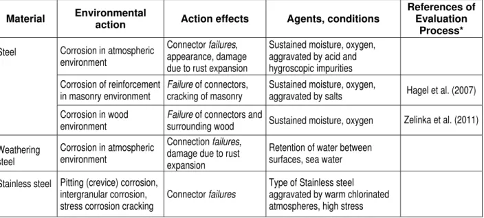
5 .2 De sign for dura bilit y of w a ll a sse m blie s 5.2.1 Introduction The general principles that are to be used should be based on the precepts set out in in standard ISO 13823 [11]. Thereafter, and depending on the type of envelope assembly for which the design of durability is to be prepared, an appropriate set of environmental actions and corresponding action effects are defined for a specific wall system based on the anticipated modes of failure and where the cladding, connectors or the structure is vulnerable to degradation arising from internal and external environmental action. A notional list of environmental actions and related effects that cause degradation and loss of resistance for selected types of wall assemblies is given in Table 2. The information provided in Table 2 represents examples of wall and cladding types, metal connectors and wall structures and although it is neither complete nor a comprehensive listing, it does provide useful information on the type of material or component degradation model to consider using when configuring a hygrothermal simulation model.
Page 13 of 35 The types of wall assemblies have been delineated with respect to their conformance to NBC Part 5 (Environmental Separation) and to NBC Part 9 (Housing and Small Buildings). As well, for any given type of wall assembly conforming to requirements given in either NBC Part 5 or Part 9, a distinction has been made in regard to both the type of structure (e.g. steel, concrete, masonry, wood and light‐gauge steel), metal connector and cladding type. As such, the environmental actions and effects of degradation arising from these actions for the structure, connector or cladding are respectively denoted for each of the types of wall assemblies listed in Table 2. Each of the five (5) items provided in Table 1 that relate to Figure 1 are shown in the respective boxes of Figure 2 and suggest conformity of the approach to that of the standard; the general approach follows that developed in the WoodExter [17] project on the service life of wood‐frame walls.
Table 1 – Conformity between approach and ISO 13823 [11]
ISO 13823 Figure 2 Adapted approach Figure 3
Structure environment Climate loads & interior conditions, wall configuration & hygrothermal
properties of component materials
Transfer mechanisms Forming part of hygrothermal model
Environmental actions Forming part of performanceattributes
Action effects Forming part of performance criteria
Loss in resistance Structural safety (ULS) Loss in serviceability Serviceability (SLS)
Standards appropriate to each of the elements given in Figure 2 are provided in Table 3; these are based either on existing standards, accepted practice, or pertinent reference information. For each of the elements, the type of standard is given and the candidate standard, or reference to pertinent literature, is provided; in instances where more than one standard is available both have been identified. Applying the ISO 13823 standard permits: Ensuring uniformity of input to a defined model; Providing a consistent means to assess the response of building elements on the basis of results from simulation and relating the response to accepted performance criteria, Obtaining a reproducible and demonstrable means of verifying designs for durability of building materials, components and wall assemblies.
Page 14 of 35
Figure 2 – General scheme for determining the expected durability of an envelope assembly (adapted from the approach developed by Jermer [17])
Aesthetics Local climate loads (exterior) Design representation Factors affecting exposure S (variable functn) Severity of Exposure Hygrothermal response model R (variable functn) Degree of resistance Material properties & response to micro‐environment Configuration of component layers, gaps & drainage Performance criteria Structural safety (ULS) Serviceability (SLS) Performance attributes
Table 2 – Defining environmental actions as may be due to hygrothermal and related effects that cause degradation and loss in resistance for selected types of wall assemblies
Envelope assembly type
Degradation of structure or connectors arising from Degradation of cladding arising fromCladding type Metal
Connectors Wall structure
Environmental
actions Action effects
Environmental
actions Action effects
NBC Parts 3/4/5
Steel or Concrete frame with infill of: - Masonry veneer (MV),
EIFS, Metal (M), Insulated metal composite (IMC)
Ties, anchors, fasteners, supports (shelf
angles)
Steel stud Corrosion Tie, anchor fastener failure Freeze-thaw of MV; dilation of EIFS MV: spalling of units, disintegration of mortar joints MV, ETICS Ties, anchors,
fasteners Masonry block Corrosion
Tie, anchor, fastener failure Freeze-thaw of MV; dilation of ETICS MV: spalling of units, disintegration of mortar joints Concrete panel (C); ETICS Anchors,
fasteners Precast concrete panel Corrosion Anchor, fastener failure Freeze-thaw of C; dilation of ETICS Spalling, disintegration C Anchors Insulated concrete
panel Anchor, failure Freeze-thaw Spalling, disintegration NBC Part 9 Housing & Small Buildings
Light-weight wood or steel frame - MV Ties, anchors,
fasteners
Light-weight wood frame
Fungal growth and fungal decay
Mould growth
& wood decay Freeze-thaw
Spalling, disintegration Wood-based (W) Fasteners “ Above & metal
corrosion
Wood decay; fastener failure
Fungal growth and decay
Mould growth & wood rot Cement-based (CB) Fasteners “ Above & metal
corrosion
Wood decay;
fastener failure Freeze-thaw Disintegration Plastic (P); Fasteners “ Above & metal
corrosion
Wood decay;
fastener failure Oxidation
Crazing, cracking EIFS Fasteners “ Above & metal
corrosion
Wood decay;
fastener failure Oxidation
Crazing, cracking MV, W, CB, P, M, EIFS Fasteners Light-weight steel
frame
Above & metal corrosion
LGSS failure
Table 3 – Definitions as relate to performance-based approach for design for durability of wall assemblies
Define Elements Type of Standard Candidate Standard or sources of information
(S) Severity of exposure load Structural environment (boundary conditions) Interior environmental conditions Define interior conditions
ANSI/ASHRAE 160-2009 Criteria for Moisture-Control Design Analysis in Buildings
Exterior environmental conditions
Define & characterise climate and moisture loads (e.g. wind-driven rain loads)
ISO 15927-3:2009 Hygrothermal performance of buildings - Calculation & presentation of climatic data -- Part 3:
Calculation of a driving rain index for vertical surfaces from hourly wind & rain data
ISO 15927-4:2005 Hygrothermal performance of buildings -- Calculation & presentation of climatic data -- Part 4: Hourly data for assessing the annual energy use for heating & cooling
Factors affecting degree
of exposure Define factors
ISO 15927-3:2005 Hygrothermal performance of buildings -- Calculation & presentation of climatic data -- Part 3:
Calculation of a driving rain index for vertical surfaces from hourly wind and rain data
(R) Degree of resistance to imposed loads Transfer mechanisms Hygrothermal model– characterise model & design representation & configuration of wall
component
Methods for characterising hygrothermal models
EN 15026:2007-07– Hygrothermal performance of building
components and building elements – Assessment of
moisture transfer by numerical simulation ; ASTM E3054/E3054M − 16 Standard Guide for Characterization and Use of Hygrothermal Models for Moisture Control Design in Building Envelopes Material properties and
response to micro-environment
Define material
properties Refer to list of material property standards in Table 4
Environmental
actions Performance attributes
Define performance attributes of specific
component or material
Refer to § 9. Performance evaluations in which attributes of specific component or material are referenced
Action effects Performance criteria
Define performance criteria for hygrothermal
performance of building components
Refer to § 9. Performance evaluations in which criteria of specific component or material are referenced
Page 17 of 35 5.2.2 Evaluation procedure The procedure for carrying out the durability evaluation is summarised in Figure 3. It proceeds in step‐wise fashion with the initial step being to characterise the hygrothermal model; this is undertaken in accordance with the instructions provided in § 6.2 relating to the characterisation of hygrothermal tools using either standard EN 15026 [8] or standard ASTM E3054; the use of one or the other standard being dependent on the jurisdiction (i.e. countries as might adhere to one or the other standard) in which work is to be completed. The procedure is intiated with a selection for the design service life of the structure (). Guidance in respect to the design service life of wall assemblies can be found in standard CSA S478 [7]. Thereafter, each step is followed in turn, with the corresponding details provided for each step in the section immediately adjacent to the description. Thus, for step , in which the user is required to “Characterise (the) hygrothermal model”, details for this step are provided in § 6.2 “Hygrothermal simulation tools”; the reference standard for this task is given as EN 15026:2007 [8] / ASTM 3054 [2].
Page 18 of 35
Figure 3 – Summary of procedure for completing a durability evaluation
Define Moisture loads arising from climate Define interior conditions Define model configuration of wall type Characterize hygrothermal model Define material & component properties of wall Define performance attributes Define performance criteria Undertake simulations Report results Select design service life of structure Evaluate Outputs 7 .1 Ex t e rior bounda ry c ondit ions
7 .2 I nt e rior bounda ry c ondit ions 8 . Doc um e nt a t ion of input da t a 6 .2 H ygrot he rm a l t ools (EN 1 5 0 2 6 :2 0 0 7 ) 6 .3 M a t e ria l prope rt ie s / T a ble 4 9 . Pe rform a nc e e va lua t ion a t t ribut e s
9 . Pe rform a nc e c rit e ria 9 . Pe rform a nc e e va lua t ion proc e ss
1 0 . Re port ing 6 .1 De sign life (DL) (CSA S4 7 8 ) I s Est im a t e d DL < DSL Y ES
11
De pe nde nt of w a ll st ruc t ure a nd c la dding t ype
Alt e r de sign & re -c om put e re sult s
N O`
Re fe r t o Anne x A t o E for re spe c t ive w a ll
building e le m e nt pe rform a nc e a t t ribut e s,
Page 19 of 35
6 . Proc e dure s
6 .1 De sign Se rvic e Life
The target or specified design service life (DSL) for the structure may be taken from CSA S478 Table 2 [7].
6 .2 H ygrot he rm a l sim ula t ion t ools
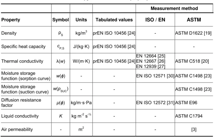
The European standard EN 15026:2007‐07 [8] or the standard ASTM E3054 [2] are to be used as a basis for conducting analytical procedures to determine the hygrothermal response of wall assemblies subjected to exterior and interior boundary conditions and moisture loads; boundary conditions are defined in §7 of this guideline document. In the EN 15026 standard, for example, the equations to be used in a hygrothermal simulation method for calculating the non‐steady state transfer of heat, air and moisture through building structures are defined and include: • Heat storage in dry building materials and absorbed water; • Heat transport by moisture‐dependent thermal conduction; • Heat transport by convection (air leakage) and radiation (in cavities) • Latent heat transfer by vapour diffusion; • Moisture storage and release by vapour sorption, desorption and capillary forces; • Moisture transport by vapour diffusion; • Moisture transport by liquid transport (surface diffusion and capillary flow). • Moisture transport by convection (air leakage) The equations described in this standard account for the following climatic variables: • Internal and external temperature; • Internal and external humidity; • Solar and thermal (longwave) radiation; • Precipitation (normal and wind‐driven rain); • Wind speed and direction. The hygrothermal equations described in this standard must not be applied in cases where: • Two‐dimensional effects play an important part (e.g. rising damp, conditions around thermal bridges, effect of gravitational forces, and air leakage path effects); • Hydraulic, osmotic, electrophoretic forces are present. 6 .3 M a t e ria l prope rt ie s Hygrothermal simulation tools require input of the physical properties of the materials and components used in the model configuration of the envelope assembly. A list of relevant material
Page 20 of 35 properties is provided in Table 4 together with sources of tabulated values and measurement methods. The values for density, specific heat capacity and thermal conductivity can be derived from standards ASTM C518 or EN 12664, [25] EN 12667 [26], and EN 12939 [27] whereas the sorption curve for the moisture storage function may be derived from standards ASTM C1498 or EN 12571 and pressure plate measurements [15], [5]. For porous materials, and in cases of high water content, the liquid transport function has a particular influence on the moisture transport behaviour. The material property to describe this process is the “liquid conductivity” or the “liquid diffusivity”. Both transport coefficients are linked by the following equation for liquid conductivity ( ).
[1] These transport coefficients, which are highly dependent on water content, are determined by the measurement of water‐content profiles in building materials using different techniques or by approximations using the water absorption coefficient (EN ISO 15148, [28]) and drying behaviour as referenced in [17].
Table 4 – Basic hygrothermal material property data set
Measurement method Property Symbol Units Tabulated values ISO / EN ASTM Density ρS kg/m3 prEN ISO 10456 [24] - ASTM D1622 [19] Specific heat capacity cP,S J/(kg·K) prEN ISO 10456 [24] - -
Thermal conductivity (w) W/(m·K) prEN ISO 10456 [24]
EN 12664 [25] EN 12667 [26] EN 12939 [27]
ASTM C518 [20] Moisture storage
function (sorption curve) w(ϕ) - - EN ISO 12571 [30] ASTM C1498 [23] Moisture storage
function (suction curve) w(pSUC) - - ASTM C1498 [23]
Diffusion resistance
factor μ(ϕ) kg/m·s·Pa - EN ISO 12572 [31] ASTM E96
Liquid conductivity K kg m-2 s-½ - - ASTM C1794
Air permeability - m2 - - [3]
Page 21 of 35
7 . Bounda ry c ondit ions
In this section information is provided on defining both the interior and exterior boundary conditions to which the model configuration of the envelope assembly is to be subjected.
7 .1 Ex t e rior bounda ry c ondit ions
Exterior boundary conditions, for the purposes of development of the hygrothermal model, include the input of the following variables: Wall orientation, including but not necessarily limited to direction of exposure, elevation range of exposure, and inclination. Climate loading exposure condition based on climatic data files from reliable sources, such as Environment Canada for precipitation, temperature, relative humidity, wind speed and direction, solar and longwave radiation and extent of cloud cover. Convection and radiation film coefficient at external wall surfaces Such information can be found in the second row of Table 3 under the column “Define Elements”: “Exterior environmental conditions” including factors that affect degree of exposure.
7 .2 I nt e rior bounda ry c ondit ions
Interior boundary conditions, for the purposes of this guideline, refer to the following variables used in the hygrothermal model: Initial temperature, relative humidity, and moisture content of the individual layers within the cross‐section of the envelope assembly configuration. Interior environment operating conditions, including temperature, relative humidity and pressure differential across the envelope assembly. Convection and radiation film coefficient at internal wall surfaces Assumptions in respect to air leakage for condensation analysis. Such information can be found in the first row of Table 3 under the column “Define Elements”: “Interior environmental conditions”
Page 22 of 35
8 . Doc um e nt a t ion
8 .1 Ge ne ra l The detailed documentation of input and output data of numerical simulations is an essential prerequisite to assess and verify the calculation results. As a rule the documentation must be such that any user repeating the simulation as documented will obtain identical results. Therefore the documentation must at least include the following items.8 .2 Proble m de sc ript ion 8.2.1 General The problem description must contain all the information required prior to the start of the calculation. 8.2.2 Scope and subject of simulation • Definition of the problem and reason for employing hygrothermal simulation • Geographical location • Construction details of the building material, component or assembly under examination • Practical background information (e.g. building type and use) • Design service life of building and building elements • Output parameters required • Duration of simulation 8.2.3 Initial conditions • Initial temperature distribution • Initial moisture distribution • Date and time for the start of the simulation 8.2.4 Boundary conditions • Internal and external climate conditions, origin and time interval; the method of constructing the climate data sets must be specified • Transformation of climate data to boundary conditions (e.g. determination of wind‐ driven rain load) • Surface heat transfer coefficients 8.2.5 Material parameters • Documentation of material properties by tables and graphs • Source of material data • Assumptions and approximations
Page 23 of 35 8.2.6 Mesh geometric configuration and related details • Documentation and schematic of geometric configuration used to represent the construction details of the wall assembly, including as modelled dimensions • Details on the mesh distribution imposed on the geometric configuration and description of the results of a mesh independence study
8 .3 H ygrot he rm a l m ode l a nd num e ric a l solut ion 8.3.1 General The documentation must contain all information related to the calculation model and the numerical parameters selected for the simulation. 8.3.2 Simulation tool Name and version of the software tool. Brief description of the capabilities and limitations of the software tool Prior validation of the model for similar benchmark applications; the model must first be configured and results obtained using as a reference the work described in the different annexes A to E of this guideline. 8.3.3 Numerical simulation Discretisation (numerical spatial grid). Time intervals (time steps). Numerical control parameters (accuracy of solution).
Page 24 of 42
9 . Pe rform a nc e e va lua t ions
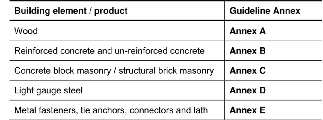
Performance evaluations for building elements comprised of: wood or wood‐based products; reinforced concrete, and un‐reinforced concrete products; concrete block masonry and structural brick masonry; light gauge steel, and; metal fasteners, metal tie anchors, metal connectors and lath are provided, respectively, in Table 5.
Table 5 - Performance Evaluations for Building elements Building element / product Guideline Annex
Wood Annex A
Reinforced concrete and un-reinforced concrete Annex B
Concrete block masonry / structural brick masonry Annex C
Light gauge steel Annex D
Metal fasteners, tie anchors, connectors and lath Annex E
Building element / product: materials, wall components and assemblies
The performance attributes, criteria, and evaluation process of the building elements are each described in the respective Annexes and are to be used in the hygrothermal model to permit interpretation of the results obtained from the hygrothermal analysis of the wall section being scrutinized and the individual components of which the envelope assembly is comprised.
Page 25 of 35
1 0 . Re port ing
1 0 .1 Displa y of re sult s The calculation results must be documented in a form that conveys all of the essential information concerning the hygrothermal performance of the building element under study. This may be done by showing graphs and tables of: • Transient distributions (profiles); • Variation with time, e.g., of temperature, moisture content, or other pertinent variables, at specific locations in the structure or integrated over material layers; • Peak values (minimum, maximum); • Mean values at points and layers and surfaces of interest of the relevant hygrothermal variables and boundary conditions such as: o Temperature, heat flow; o Water content, moisture flow; o Relative humidity; o Vapour pressure. Overall performance attributes (metrics) of the wall component and assemblies integrated over the simulation period, including, e.g.: o Total residual moisture content; o Number of freeze‐thaw cycles (if applicable) o Any index based on moisture, temperature or both (e.g. wood decay, mould, corrosion index)1 0 .2 I nt e rpre t a t ion of re sult s
The documentation of the results may be followed by an interpretation of their practical meaning. This may be done by at least one of the following means: • Comparing the resulting hygrothermal conditions with specified limits. • Checking the risk of moisture accumulation by comparing the total moisture content in the component with the accepted threshold values • Evaluating the moisture tolerance of the construction (drying potential). • Feeding the transient results into a post process model (e.g. for mould or algae growth, rot, corrosion). • Verify that moisture levels within the building material layers and the system overall do not accumulate and increase over the modeling period. (i.e., moisture levels should reach a stabilizing value asymptotically).
![Table 1 – Conformity between approach and ISO 13823 [11]](https://thumb-eu.123doks.com/thumbv2/123doknet/14046198.459650/26.918.96.822.447.700/table-conformity-approach-iso.webp)
![Table D10 - Regression constants used with annual corrosion rate given in Equation [Knotkova et al., 2010]](https://thumb-eu.123doks.com/thumbv2/123doknet/14046198.459650/46.918.185.739.485.686/table-regression-constants-annual-corrosion-given-equation-knotkova.webp)