Collisionless ion collection by non-emitting
spherical bodies in E x B fields
by
Leonardo Patacchini
S.M., Massachusetts Institute of Technology (2007)
Ingenieur dipl6m6 de l'Ecole Polytechnique (X2002)
Submitted to the Department of Nuclear Science and Engineering
in partial fulfillment of the requirements for the degree of
Doctor of Philosophy in Applied Plasma Physics
at the
MASSACHUSETTS INSTITUTE OF TECHNOLOGY
February 2010
@ Massachusetts Institute of Technology 2010. All rights reserved.
A uthor ...
...
Department of Nuclear Science and Engineering
/1 ii
i/iOctober 6, 2009
Certified by...
Ian H. Hutchinson
Professor
A-
Thesis Supervisor
Certified by...
Brian LaBombard
Principal Isearch Scientist
171Thesis Reader
Accepted by...
/
/
Jacquelyn C. Yanch
Chair, Department Committee on Graduate Students
ARCHIVES
MASsACHUSETTS INS EOF TECHNOLOGY
MAR 12 2010
LIBRARIES
Collisionless ion collection by non-emitting spherical bodies
in E
xB fields
by
Leonardo Patacchini
Submitted to the Department of Nuclear Science and Engineering on October 6, 2009, in partial fulfillment of the
requirements for the degree of
Doctor of Philosophy in Applied Plasma Physics
Abstract
The three-dimensional interaction of a magnetized, collisionless flowing plasma with a non-emitting conducting sphere is solved in the entire range of physically allowed parameters, in the ion-collecting regime. This can be considered as the "spherical Mach probe" problem, establishing how the ion flux to the surface varies with orien-tation and external velocity; the study is however of broader interest, as the sphere can also be seen as a dust particle or any ionospheric body. The core tool developed for this study is the fully parallelized (particle + field solver) Particle-In-Cell code
SCEPTIC3D, three-dimensional evolution of SCEPTIC, accounting for the full ion
distribution function and Boltzmann electrons.
Investigations are first carried out in the quasineutral limit. Results include a report of ion current dependence on the external plasma parameters, as well as a theoretical calibration for transverse Mach probes with four electrodes oriented at
450 to the magnetic field in a plane of flow and magnetic field, valid for arbitrary temperature and ion magnetization. The analysis is preceded by an independent semi-analytic treatment of strongly magnetized ion collection by oblique surfaces, successfully validating SCEPTIC3D's behaviour.
The finite shielding length regime is more complex, and an important transition in plasma structure occurs when the Debye length goes over the average ion Larmor radius. Studies of ion collection show that the ion current can exceed the (unmag-netized) OML limit at weak magnetization, and the Mach probe calibration method proposed in the context of quasineutral plasmas holds up to Debye lengths equal to
about 10% of the probe radius.
A further analysis consists in calculating the force exerted by the flow on spherical
dust. In short Debye length plasmas a strong drag component antiparallel to the convective electric field forms, causing the dust to spin faster than what predicted
by its Larmor frequency. At intermediate and large Debye length the ion-drag in the
direction of transverse flow is found to reverse in subsonic conditions, but the internal Laplace force appears to be positive, and larger in magnitude than the negative ion-drag.
Thesis Supervisor: Ian H. Hutchinson Title: Professor
Thesis Reader: Brian LaBombard Title: Principal Research Scientist
Acknowledgments
As the end of my journey as a doctoral student approaches, it is with the deepest gratitude that I acknowledge those who contributed to its success.
First and foremost I would like to thank my advisor Pr. Ian Hutchinson for his trust and support. I measure the great liberty that I benefited from, be it in setting my own research directions or in undertaking abundant and often unrelated coursework. I shall also not forget his uninterrupted time-commitment, as well as prompt proofreading of countless papers and thesis drafts. Closely working with a scientist having such a deep physical insight has been a pleasure, and after four years I can corroborate what the FRench consul in Boston told me after meeting Pr. Hutchinson at a cocktail:
"Your advisor looks pretty smart !".
I am deeply indebted to the MIT Nuclear Science and Engineering Department
and the Plasma Science and Fusion Center faculty, scientists and support staff. In particular Pr. Sidney Yip, Pr. Ronald Parker, Pr. Jeffrey Freidberg, Pr. Miklos Porko-lab, Pr. Ian Hutchinson and Dr. Peter Catto, with whom I had close contact through classes; my reader Dr. Brian Labombard for his valuable advices and comments; Dr. John Wright and Dr. Paul Bonoli for helping me use the cluster Loki; and last but not least Valerie Censabella for her administrative support.
I acknowledge financial support from the MIT Nuclear Science and Engineering
Department and the US Department of Energy, as well as the kind hospitality of the Alcator group for letting me use and abuse the control-room workstations.
I must express my sincere gratitude to Pr. Giovanni Lapenta for hosting me in his research group at Los Alamos National Laboratory during the summer 2006; this period resulted in a fruitful collaboration, and helped me mature the knowledge gathered in my first year a MIT. I am also indebted to the late Pr. Hiroshisa Noguchi, who hosted me in his research group at Keio University during the summer 2008 despite very unfavorable circumstances; I will not forget you.
My time here wouldn't have been such a wonderful experience without the joy
Nagaya, Nagatomi, Matsumura, Shiomi, Yamanaka and Fujisaki Sensei; as well as to Daniela Reichert for helping me organize my stay in Japan during the summer 2008. I am deeply indebted to my parents for their love and support throughout my entire life, and for their encouragement to undertake my Doctoral research in the
Contents
Abstract ... ... 3 Acknowledgments ... 5 Contents ... ... 7 List of Figures . . . . 11 List of Tables . . . . 14 I Thesis outline 15 1.1 Background . ... . . . .. 15 1.2 Nomenclature.... . . . . . . . . 17 1.3 Structure... . . . . . . . . . . .. 19II Probes in zero Debye length, strongly magnetized plasmas 23 II.1 Foreword on Langmuir probes . . . . 23
11.1.1 Uninagnetized probes . . . . 23
11.1.2 M agnetized probes . . . . 28
11.2 Foreword on magnetized, transverse Mach probes . . . . 32
11.2.1 The Mach probe concept. . . . . .. 32
11.2.2 General isothermal formulation. . . . .. 34
11.2.3 Relative weight of the different transport mechanisns . . . 38
11.2.4 The question of ion recycling . . . . 41
11.3 The quasi-collisionless convective model . . . . 42
11.3.1 Presheath equations. . . . . . . . . 42
11.3.2 Discussion of the diffusive limit . . . . 43
11.3.3 Convective limit.. . . . . . . . 44
11.4.1 Solution method . . . . .
11.4.2 Isothermal fluid solution . . . .
11.4.3 Analogy with the plasma expansion into a vacuum .
11.4.4 Free-flight solution . . . .
11.5 Results and physical discussion. . . . . . ..
11.5.1 Plasma profiles . . . .
11.5.2 Ion flux-density to a flat probe . . . ... . . . . ..
11.5.3 Extension to transverse Mach probes . . . .
11.5.4 Macli probe calibration . . . .
11.6 2D analytic free-flight density contours . . . .
11.6.1 Strongly magnetized limit... . . . ..
11.6.2 Comparison with the magnetic-free regime . . . . .
III SCEPTIC3D
III.1 Model and computational method. . . ..
III.1.1 Problem formulation . . . .
111.1.2 Code mesh . . . . 111.1.3 Orbit integration . . . . 111.2 Quasineutral operation . . . . .. 111.2.1 Boundary conditions. . . ... 111.2.2 Accuracy . . . . 111.2.3 Axisymmnetry resolution . . . .
111.3 Finite Debye length operation . . . . 111.3.1 Parallelized Poisson solver . . . .
111.3.2 Electrostatic Maxwell stress tensor .
III.3.3 Magnetostatic Maxwell stress tensor .
IV Spheres in zero Debye length, arbitrarily magnetized plasmas
IV.1 Plasmia profiles . . . .
IV.1.1 Infinite ion magnetization.. . . . ..
IV.1.2 Intermediate ion magnetization . . . .
. . . . 45 . . . . 48 . . . . 49 . . . . 49 . . . . 50 . . . . 50 . . . . 52 . . . . 54 . . . . 57 . . . . 59 . . . . 59 . . . . 61 63 . . . . 6 3 . . . . 6 3 . . . . 6 6 . . . . 7 2 . . . . 7 3 . . . . 7 3 . . . . 7 4 . . . . 7 6 . . . . 7 8 . . . . 7 8 . . . . 8 3 . . . . 8 9
IV.2 Ion saturation current.. . . . . . . . 97
IV.2.1 Free-flight current . . . . 97
IV.2.2 Self-consistent ion current... . . . . . . . . 99
IV.3 Transverse Mach probe calibration . . . . 101
V Spheres in infinite Debye length, arbitrarily magnetized plasmas 109 V.1 Foreword on dust charging in the uninagnetized regine . . . . 110
V.1.1 Dusty plaslas . . . . 110
V.1.2 Orbit Motion Limited shielding . . . . 113
V.1.3 Orbit Motion Limited charging . . . . 117
V.2 Ion collection in the drift approximation . . . . 118
V.2.1 1D-kinetic/2D-drift model... . . . .. 119
V.2.2 Results and physical discussion . . . ... . . . .. 124
V.2.3 The question of stationary magnetoplasinas . . . . 126
V.3 Review of collection in stationary, large Debye length magnetoplasmas128 V.3.1 Parker-Murphy upper bound current . . . . 128
V.3.2 Free-flight nagnetized current.... . . . .. 130
V.3.3 Helical upper bound current . . . . 133
V.3.4 Ion current calculations . . . . 134
V.4 Ion collection in arbitrarily inagnetized flowing plasmas . . . . 136
V.4.1 Total ion current . . . . 136
V.4.2 Angular ion flux-density distribution . . . . 138
V.4.3 Plasma profiles . . . . 139
VI Spheres in finite Debye length, arbitrarily magnetized plasmas 141 VI.1 Foreword on electron-collecting space tethers... . . .. 142
VI.1.1 Electrodynamic tethers. . . . . .. 142
VI.1.2 Electron collection by the TSS subsatellite . . . . 143
VI.2 Plasm a profiles . . . . 146
VI.2.1 Strong ion magnetization . . . . 146
VI.3 Self-consistent ion current... . . . . . . . 155
VI.3.1 Current dependence on ion magnetization . . . . 155
VI.3.2 Current-Voltage characteristics at low Debye length . . . . 157
VI.3.3 Transverse Mach probe calibration . . . . 161
VII Dust grain dynamics 165 VII. 1 Foreword on uninagnetized (lust dynamics . . . . 165
VII.1.1 Dielectric response approach to the ion-drag force . . . . . 166
VII.1.2 Binary collision approach to the ion-drag force . . . . 168
VII.1.3 Force Evaluation with SCEPTIC . . . . 171
VII.2 2D calculations in parallel-drifting magnetoplasnas . . . . 172
VII.2.1 Free-flight calculations . . . . 172
VII.2.2 Self-consistent calculations . . . . 174
VII.3 Capacitance calculations in E x B fields . . . . 178
VII.4 Force calculations in E x B fields . . . . 179
VII.4.1 Free-flight calculations at infinite magnetization . . . . 179
VII.4.2 Calculation of the non ion-drag forces . . . . 183
VII.4.3 Momentum conservation in SCEPTIC3D . . . . 186
VII.4.4 Ion-drag solutions at low Debye length . . . . 187
VII.4.5 Ion-drag solutions at intermediate and large Debye length . 191 VIIConclusions 199 VIII.1 Position of the problem and computational approach . . . . 199
VIII.2 Summary of physical results... . . . . . . . . 200
VIII.3 Directions for future work . . . . 203
A Boltzmann electron response 207 A. 1 Electron density distribution . . . . 207
List of Figures
I-1 T hesis M ap . . . . .
11-1 Magnetized Langmuir probe characteristics . . . .... 11-2 Diffusive presheath model . . . .
11-3 Magnetic presheath... . . . .
11-4 Example of Gundestrup probes . . . . 11-5 Planar probe geometry . . . .
11-6 Ion orbits in p - v space... . . . . . . . . 11-7 Evolution of the ion distribution function along the presheath . .
11-8 Evolution of density and temperature along the presheath . . . . .
11-9 Evolution of the parallel ion flux-density along the presheath . . .
II-10 Mach probe calibration factor... . . . . . . .
11-11 Ion flux-ratios . . . ...
11-12 2D convex probe with circular cross-section . . . .
11-13 Angular distribution of ion saturation flux . . . .
11-14 Magnetized free-flight density contours . . . . 11-15 Comparison of magnetized and unmnagnetized free-flight contours .
III-1 111-2 111-3 111-4 111-5 111-6 111-7 Problem geometry... . . . . . . . . . 3D and 2D views of SCEPTIC3D's computational domain .
ID representation of the computational grid . . . .
Computational noise in the quasineutral regime . . . . 2D benchnmarking of SCEPTIC3D in the quasineutral regime
Solver accuracy 1 . . . . Solver accuracy 2 . . . . 67 . . . . 67 . . . . 69 . . . . 76 . . . . 77 . . . . 88 . . . . 88
IV-1 Problem reduction to two dimensions in the AD, < Rj < R, scaling 92
IV-2 Density contour-plots at strong magnetization. . . . .. 94
IV-3 Comparison between the ID-kinetic treatment and SCEPTIC3D . . 95
IV-4 Parallel ion temperature contour-plots . . . . 96
IV-5 Density contour-plots at intermediate magnetization . . . . 98
IV-6 Free-flight ion current as a function of magnetization . . . . 100
IV-7 Self-consistent ion current as a function of magnetization . . . . 102
IV-8 Angular ion flux-density distribution . . . . 103
IV-9 3D color-plot of ion flux-density to the probe . . . . 104
IV-10 Upstream to downstream flux ratios at qj = 37r/4 and
71
= r/4 . . . 106IV-11 Calibration factor as function of magnetization and temperature . . 106
V-1 Example of dust particles . . . . 111
V-2 Dust created by the Alcator C-Mod lower hybrid launcher . . . . 112
V-3 OML ion current to a spherical probe . . . .. 119
V-4 3D ion orbits in physical space . . . . 123
V-5 Ion current in the drift approximation at infinite Debye length . . . 125
V-6 Ion flux-ratios in the drift approximation at infinite Debye length 127 V-7 Total ion current in the quasineutral regime . . . . 127
V-8 Critical magnetic bottles in a Coulomb potential . . . . 130
V-9 Helical orbits parametrization... . . . . . . .. 131
V-10 Magnetized ion current to a stationary Coulomb sphere . . . . 136
V-11 Total ion current as a function of 13; at infinite Debye length . . . . 137
V-12 Angular ion flux-density distribution . . . . 138
V-13 Critical streamlines as a function of probe potential . . . . 140
V-14 Critical streamlines at low magnetization . . . . 140
VI-1 Artist view of a space tether . . . . 143
VI-2 C-V characteristic from the TSS-1R experiment . . . . 144
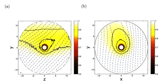
VI-3 Ion charge-density contour-plots on the {0, ey, ez}-plane . . . . 147
VI-5 VI-6 VI-7 VI-8 VI-9
VI-10
VI-11 VI-12 VI-13 VI-14VI-15
Potential contour-lines at strong magnetization . . . . 150
Parallel temperature contour-lines . . . . 151
Perpendicular temperature contour-lines . . . . 152
Charge-density contour-plots on the
{0,
ey, e,}-plane . . . . 153Charge-density contour plots on the {0, ex, ey}-plane . . . . 153
Cyclotron wakes in the presence of cross-field drifts . . . . 154
Ion current as a function of magnetization . . . . 156
C-V characteristics at finite Debye length . . . . 158
Ion current versus the Parker-Murphy upper bound . . . . 160
Critical magnetic bottles in a D-H potential... . . . . . . . . 162
Upstream to downstream flux-ratios at l = 37r/4 and q = r/4 . . . 163
VI-16 Calibration factor as function of magnetization and temperature . .
VII-1 Unmagnetized ion-drag force as a function of drift velocity . . . . .
VII-2 Free-flight ion-drag as a function of magnetization in parallel flows VII-3 Self-consistent drag as a function of magnetization in parallel flows
VII-4 Effective shielding length in E x B fields . . . .
VII-5 Free-flight drag as a function of magnetization in cross-field flows . .
VII-6 Momentum conservation in SCEPTIC3D. . . . .
VII-7 Ion-drag at ADe = 0.03 in pure cross-field flows . . . . . . . . .. VII-8 Non ion-drag forces at ADe = 0.03 in pure cross-field flows . . . .
VII-9 Jon-drag at ADe = 0.03 . . . .
VII-10 Jon-drag at moderate and large Debye length in the ey-direction VII-1 1I on-drag at moderate and large Debye length in the ex-direction VII-12 Non ion-drag forces at moderate and large Debye length . . . .
A-I Two orbit types in the presence of a magnetic field . . . .
164 172 174 177 180 182 188 190 191 192 194 195 197 209
List of Tables
1.1 Examples of magnetized plasma-collector interaction . . . . 17
1.2 Thesis nomenclature... . . . . . . . . . 19
11.1 Sample plasma parameters for typical Alcator C-Mod SOL conditions 40
Chapter I
Thesis outline
1.1
Background
Interest in the physics of plasma interaction with ion-absorbing bodies has not faded since the almost century-old work of Mott-Smith and Langmuir [1, 2], to whom the technique of flux-sensing (or electric) probes is due. The concept of electric probes is simple: from the insertion of one or more small electrodes in a discharge and the measure of collected currents, one seeks to infer local plasma properties such as the electron temperature (Langmuir probes) or the plasma drift velocity (Mach probes). Because biased (usually negatively), probes modify the neighbouring electrostatic potential and particle distribution functions. The challenge is therefore not so much the experimental operation itself, rather the development of reliable theories relating the collected fluxes to the unperturbed plasma properties [3, 4].
To develop such theories, it is customary to consider bodies with spherical ge-ometry. Of course this simplification greatly eases the analysis, but perhaps more important broadens the applicability of the developed results to the more recent field of dusty plasmas [5]. Because electron mobility is much higher than the ions', dust particles usually tend to charge until they acquire a potential negative enough to repel the excess electrons and collect a zero net current. Calculating the charging rate, as well as quantities such as the drag force exerted on the particles by drifting plasmas, involves the same physics as the interpretation of probe measurements, albeit dust
grains are usually two to three orders of magnitude smaller than probes.
The motivation for this thesis is to improve our understanding of ion collection by negatively charged electrodes in flowing magnetized plasmas, in the entire range of ion magnetization O3 and electron Debye length over electrode radius ADe. In order to concentrate on basic plasma phenomena, the complexity of non-plasma physics is reduced as follows. It is first assumed that the probe is ideal (we refer to "probe", "electrode" or "dust" regardless of the physical nature of the collector), that is to say it absorbs every particle striking it and releases neutral atoms or molecules at a rate that balances the incoming flux of ions. Deviations from ideality come from different solid state physics reactions resulting in electron emission at the surface; those phenomena will be disregarded bearing in mind that they might not be negligible in situations involving for instance ionospheric plasmas, where UV radiation can cause strong enough photoemission to positively charge orbiting bodies. It is further assumed that the probe bias is negative enough for a Debye sheath to form; in this regime, the electron density and the electrostatic potential around the probe are simply related
by a Boltzmann exponential.
Despite the unfortunate insufficiency of communication between laboratory-plasma and space-physics communities, the interaction of spacecraft with their environment shares many properties with the above mentioned probes or dust particulates. How-ever because the quantity of interest is usually the attracted electron rather than ion current, no Boltzmann electron treatment is possible and more specific calculations are required. Examples of plasmas where the average ion Larmor radius RL compares to the size of relevant perturbing objects are proposed in table (1.1).
A convenient way to treat the problem is to follow the Particle-In-Cell (PIC)
approach [8]: instead of directly solving the continuity equation for the ion distribu-tion funcdistribu-tion coupled to Poisson equadistribu-tion for the potential, a large set of computa-tional particles are advanced according to the equations of motion. Using the 2D/3v (two-dimensional physical space, three-dimensional velocity space) PIC code SCEP-TIC [9, 10, 11, 12], the problem has been comprehensively solved in unmagnetized plasmas. The main challenge in the presence of a background magnetic field is the
Tecc Toc B Nc, RLe RL ADe RL
Com-(eV) (eV) (T) (r- 3) (pm) (pm) (pm) pares to
Mid-plane SOL 10 30 5 1018 1.9 200 23 dust
Divertor region 5 5 5 102 1.3 81 1.7 dust
Magnetron 3 0.025 2.4 . 10-2 2.5. 1016 210 5.3- 103 81 probe F-layer 0.1 0.1 5- 10-5 101 1.9. 104 3.2. 106 7.4. 103 satellite
Table 1.1: Examples of plasmas where the average ion Larmor radius RL compares
to the size of dust particles (R, - 1 - 200pm), flux-sensing probes (R, - 1-5mm1n), or
man-made satellites (R, ~ 1m). The first two examples are typical DD (D+ plasma) Tokamak plasmas. Experimental parameters for the Magnetron (Ar+ discharge) are taken from Ref. [6], and atmospheric data for the F-layer (0+ plasma) is from Ref. [7].
requirement for cross-field transport in the collector's magnetic shadow in order for the presheath to merge with the plasma at infinity. When no such effect is accounted for, only the Large Debye length plasmas when the potential distribution around the collector adopts a Coulomb form [13), or weakly magnetized plasmas where the ratio of sphere radius over mean ion Larmor radius # 1 [14] can be treated.
1.2
Nomenclature
In this thesis, special care has been taken to ensure notation consistency. The key parameters and variables are referenced in table (1.2).
Dimensional plasma parameters
Ti,
e
Ion (electron) temperature Tic Ion temperature at infinity Nc- External electron density Ni,e Ion (electron) charge-densityADe Electron Debye length Eq. (11.1)
Z Ion charge-number
m Ion mass
Vd (Total) external drift velocity
vo0, v_ Parallel and perpendicular external drift velocities
B Magnetic field
Wc Ion Larmor angular frequency 6 Angle of Vd to B
car Isothermal ion sound speed Eq. (11.20)
Vtie Ion (electron) thermal speed Eq. (11.31)
I e Ion (electron) thermal charge flux-density Eq. (11.3)
cS Bohm ion sound speed Eq. (11.9)
74 Ion adiabatic index Eq. (II.10)
C80 Cold ion sound speed Eq. (11.13)
RL Mean ion Larmor radius Eq. (11.19)
Eeny Convective electric field
<D Probe-induced electrostatic potential distribution
fiei Averaged e-i momentum transfer Coulomb collision frequency Eq. (11.34)
Dimensional probe parameters
R, Spherical probe radius
<1D, Probe mean potential (external bias) <Df Probe mean floating potential
Fixe Ion (electron) charge flux-density to the probe
Ix~e Ion (electron) total current to the probe
I Net current to the probe e (Ij - Ie)
,i,es Ion (electron) saturation charge flux-density to the probe Ii~es Ion (electron) saturation current to the probe
Dimensionless parameters
T External ion to electron temperature ratio Eq. (II.5)
ni,e Ion (electron) charge density normalized to N,
n Charge density normalized to N in quasineutral plasmas Electrostatic potential normalized to Te/e
X Electrostatic potential normalized to -Ti./Ze ADe Electron Debye length normalized to R,
A Probe radius over mean ion Larmor radius Eq. (IV.1)
A, M1 Parallel and perpendicular external isothermal Mach numbers
Wd (Total) external drift velocity normalized to vti
wO, W1 Parallel and perpendicular external drift velocities normalized to v'ei
Table 1.2: Key parameters and definitions used troughout this thesis.
1.3
Structure
Including the present outline, this thesis is structured in 7 chapters placed in logical order such as to progressively cover the
#i
- ADe parameter map in figure I-I.Chapter 2
The kinetic equation governing a strongly magnetized quasineutral transverse plasma flow past a convex ion-collecting object is solved numerically for arbitrary ion to electron temperature ratio T. The approximation of isothermal ions adopted in a
recent fluid treatment of the same plasma model [15] is shown to have no more than a small quantitative effect on the solution. In particular, the ion flux-density to an elementary portion of the object still only depends on the local surface orientation. We rigorously show that the solution can be condensed in a single "calibration factor" Me,
X=oo _= I= I I==II= SCEPTIC2D
* Chap.
2
I
- - - Chap.
3
* Chap.5
X =0
= ----De-- 'Chap. 5
0
=OO
xChap. 6-7
Figure I-1:
#
- ADe (ion magnetization - electron Debye length) parameter-space that we propose to explore in this thesis. "SCEPTIC2D" refers to previous two-dimensional investigations by Hutchinson [9, 10, 11, 12].function of r only, enabling Mach probe measurements of parallel and perpendicular flows by probing flux ratios at two different angles in the plane of flow and magnetic field.
Chapter 3
The two-dimensional parallel Particle-In-Cell (PIC) code SCEPTIC [9, 10, 11, 12], designed to solve the axi-symmetric interaction of a collisionless flowing plasma with a negatively charged ion-collecting sphere, is extensively modified to resolve the third, azimuthal dimension. The new code version SCEPTIC3D can therefore operate in the inherently three-dimensional configuration where background orthogonal magnetic and electric fields drive a cross-field flow. While the particle advance is distributed as in the 2D version, a new parallelized 3D Poisson solver based on the linear minimum residual algorithm has been developed.
Chapter 4
The ion saturation current (i.e. at zero Debye length) to a spherical probe in the entire range of ion magnetization is computed with SCEPTIC3D. Results are compared
with prior SCEPTIC calculations valid in the magnetic-free regime, and with the semi-analytic solutions of chapter 2. At intermediate magnetization (ion Larmor radius close to the probe radius) the plasma density profiles show a complex three-dimensional structure that SCEPTIC3D can fully resolve, and contrary to intuition the ion current can exceed the unmagnetized limit provided the ion temperature is low enough. Our results are conveniently condensed in a single factor Mc, function of ion temperature and magnetic field only, providing the theoretical calibration for a transverse Mach probe with four electrodes placed at 450 to the magnetic field in a plane of flow and magnetic field.
Chapter 5
First, the kinetic equation governing a strongly magnetized transverse plasma flow past a sphere in the vacuum limit (large Debye length) is solved numerically for a selection of plasma parameters. It is observed that contrary to the quasineutral strongly magnetized regime discussed in chapter 2, the ion current continuously tends towards the no-drift limit as the cross-field flow is reduced, with a sensitivity much higher than in vacuum unmagnetized conditions (OML [10]). Because the convective electric field is shielded by the conductor however, the ions only have a parallel velocity when collected and no "Mach probe"-like calibration is possible. The same problem is then solved with SCEPTIC3D accounting for finite ion magnetization, showing that the ion current to dust particles in tokamak-edge relevant conditions can exceed the litterature-assumed OML value by a significant amount.
Chapter 6
We here take advantage of SCEPTIC3D's full capabilities, by bridging the gap be-tween the quasineutral (chapter 4) and vacuum (chapter 5) regimes through the ac-countancy of finite Debye length. An important transition in plasma structure is found to occur when the Debye length goes over the average ion Larmor radius, hence the Debye sheath and magnetic presheath merge, in particular opening the possibility for weakly damped cyclotron wakefields. Studies of ion collection show
that exceeding of the OML current limit at weak magnetization also occurs in inter-mediate Debye length conditions, and the Mach probe calibration method proposed in the context of quasineutral plasmas holds up to Debye lengths equal to about 10% of the probe radius.
Chapter 7
A further analysis of interest in the finite Debye length regime is to compute the
ion-drag force exerted by the plasma on the sphere, typically a dust particle. In short Debye length plasmas a strong drag component antiparallel to the convective electric field forms, causing the dust to spin much faster than what predicted by its Larmor frequency. At intermediate and large Debye length the ion-drag component in the direction of transverse flow is found to reverse in subsonic conditions, but estimates of currents circulating inside the dust suggest that the resulting Laplace force is in the positive direction, and larger in magnitude than the ion-drag.
Chapter II
Probes in zero Debye length,
strongly magnetized plasmas
11.1
Foreword on Langmuir probes
II.1.1
Unmagnetized probes
The Langmuir probe
The development of models describing the contact between plasmas and solid surfaces, initiated by Langmuir and Mott-Smith in the 1920s [1, 2], is amongst the oldest ongo-ing endeavours of plasma physics. Original investigations were mainly motivated by the prospect of diagnosing discharge properties with a small electrode, the Langmuir probe. The method is essentially based upon interpreting the net current collected by the probe from the plasma, as a function of the applied bias voltage.
Let us consider a probe plunged in a uniform, Maxwellian plasma consisting of a single species of monoionized ions, with charge-number Z. Because the ion to electron mass ratio m/me is large and thermalization is driven by Coulomb collisions, ions and electrons equilibrate among themselves much faster than with each other. We therefore describe the ion and electron unperturbed distribution functions by Maxwellians with different temperatures Ti, and Te, but equal charge density N, and drift velocity Vd.
When the probe bias <D, is lower than space potential, <bo = 0 by convention, ions are attracted and collected at a rate in general dependent on <D,. If however the electron Debye length
ADe
o
2is much shorter than the probe size, the electrons neutralize the ions down to a thin layer at its surface called Debye sheath, and the probe is strongly shielded. In this regime it is observed that in the limit <Dp < -Te/e, the ion current i saturates to a value Ij, independent of <D,. Most electrons are on the contrary repelled, hence their current is governed by a Boltzmann factor; for collisionless unmagnetized electrons [4]:
I, = AF exp
(II),
(11.2)
where
T 1/2
po
= No
27meT 1(11.3)
is the electron thermal flux density, and A the probe area.
If we exclude surface electron emission effects, important in so-called "emissive probe" measurements, the total current I e (I, - Ie) as a function of <D, can be cast in the form [4, 31
I = it{I - exp [(ITe If (114)
where <Df is the a priori unknown floating potential, bias at which the probe current vanishes. The discharge electron temperature T can then be measured by fitting Ie,
<Df and Te in Eq. (II.4) to experimental Current-Voltage (C-V) characteristics I(<Dp).
The Bohm Condition
Because the probe acts as a particle sink and is furthermore biased, it collects ions from a perturbed plasma. Relating the ion saturation current to physical plasma properties "at infinity", such as N or the ion to electron temperature ratio
To
r = , (11.5)
2e
therefore requires an understanding of the self-consistent interaction between the probe and the plasma. The exact solution depends on the probe shape, and is in general obtained through a numerical treatment. This is usually done by assuming that (a) outside the Debye sheath the plasma is quasineutral, i.e. the ion and elec-tron charge densities are quasi-equal : Ni ~ Ne and (b) the repelled elecelec-trons are Boltzmann distributed in the entire perturbed plasma:
(<b) = Neo exp (v. (11.6)
Te
The perturbed plasma region outside the Debye sheath, where quasineutrality holds, is usually called presheath. More details on the Boltzmann electron distribution and current are given in appendix A.
Because the Debye sheath is assumed to be thin compared to the probe size, hence its local curvature radius, one can describe the presupposed collisionless ion dynamics at the sheath edge by the following one-dimensional continuity
ION O{v)
(v) + N = 0 (11.7)
and momentum
D(v) _8(NTs)8<
mN(v) = - ___ - Ze- (11.8)
equations, where in is distance from the Debye sheath edge, (v) is the ion fluid velocity towards the probe, and N = Ni = Ne. Defining the Bohm sound speed by
cis = T+-i / (II.9)
where 'i, is the effective adiabatic index
1 d(NiTi,) (11.10)
TI d Ni'
and taking advantage of quasineutrality, we can rewrite Eq. (11.8) as
C20N +
N(v)
) = 0. (I.11)It immediately appears that the system composed by Eqs (11.7,11.11) has a non con-stant solution if and only if
(v) N
= 0. (11.12)
ci N(v)
This is the Bohm condition, stating that the ion fluid velocity at the sheath edge equals the Bohm sound speed ((v) = vi, = c,). Eqs (11.7,11.11) only apply at the exact sheath edge; if ( < 0 (sheath) quasineutrality does not apply, and if ( > 0
(presheath) the physics is either multi-dimensional, or requires additional ingredients such as collisions, ionization/recombination,
Spherical probe in a cold plasma
Dimensionally, in a collisionless plasma the ion saturation current is of the order AN.co, where
5 ZTe 1/2
c5o =\e (11.13)
is the cold ion sound speed. In the specific case of stationary cold ions (Vd = 0 and
T < 1), analytic solutions can be found for highly symmetric probe geometries, such as spherical or cylindrical with circular cross-section.
Indeed in a cold ion plasma the Bohm condition states that at the sheath edge vi, = c,0. Furthermore the problem for a spherical probe in a stationary plasma
is spherically symmetric, and ion energy conservation implies that the sheath edge potential 4P, satisfies vi, = (-2Ze8 /n) i.e.
1 Te
. = .* (11.14)
Since at the sheath edge quasineutrality still holds, the ion density there is Ni, =
vis.
The probe ion current is therefore [4]
Ii, = A exp
(-)
Nc,s,(11.15)
where A
=
47rR and R, is the spherical probe radius. By definition, Ii, is equal to the electron current (Eq. (11.2)) at floating potential(DI = ITf In 2Z7r -- 1 . (11.16)
2 e m
Eq. (II.4) is typically fitted for T in the range <bp E [< <f :~ b]. For example, in
a fully ionized helium plasma (Z 2 and m ~ 7350ne): <D ~ -3.7Te/e.
Finite sheath thickness
Once the above results for the sheath entrance potential (Eq. (11.14)) and the ion current (Eq. (11.15)) are obtained in the infinitesimal Debye length regime, it is pos-sible to a posteriori estimate the sheath thickness A. One simple idea is to treat the electron density in the sheath as negligible, and solve Poisson equation between <D,
and <D8.
The calculation is discussed in Ref. [4], and the result approximately given by:
A ~ 1.02ADe [(~-P)1/2 1 [(_P)1/2 + (11.17)
where
e D
(II.18) is the normalized probe potential. The important points to notice in Eq. (11.17) is that A oc ADe and A increases with |#,l. For example if the probe is at floating
potential (Eq. (11.16)) in a pure helium plasma: A ~
4ADe-A first correction to the ion current when 4ADe-ADe R, can then be obtained by replacing A by A (1 ± A/R) 2 in Eq. (11.15). In the opposite limit ADe > Rp,
SO-called Orbit Motion Limited (OML) calculations presented in section V.1.3 apply. In this thesis chapter, we concentrate on situations where A
<
R,.II.1.2
Magnetized probes
Magnetic field effects on C-V characteristics
The presence of a background magnetic field B introduces considerable complexity to the previous picture. In particular, the ion saturation current also depends on the magnetic field strength, as well as the probe surface orientation with respect to the field lines.
Figure (TI-la) shows a schematic diagram of the tilting Langmuir probe array experiment of Matthews and coauthors [16], designed to investigate the influence of magnetic field angle on the C-V characteristics. Experiments were performed at the boundary of the DITE (Divertor Injection Tokamak Experiment) tokamak, operating with toroidal magnetic field B = 1.55T and helium plasma. The results, compiled in Fig. (II-1b), show that the the ion saturation current decreases as the angle of probe normal to magnetic field 0 approaches 900.
This can be interpreted as follows. Except for 0 = 900, fitting Eq. (II.4) to the ion saturation portion of the C-V characteristics yields an electron temperature Te ~ 25eV, that we here assume equal to Ti,. The average ion Larmor radius at infinity for a Maxwellian plasma (RL = (2vti
y
w2dw)/wc with we = ZeB/m and vti later defined by Eq. (11.31))RL~ Z1 7rTimm 1/2 (11.19)
ZeB 2
is therefore RL - 0.4mm, much smaller than the probe (40mm x 60mm). As a
consequence the ions are tied to the field lines, and only see the projection of the probe on the plane perpendicular to B.
The tokamak line-integrated electron density is 3 -1019m-3
. Arbitrarily assuming,
per-Probe Diometer 3mm 40mm
I
-20 C . 0-Probe TubeProbe Voltage (VI
Figure II-1: (a) Tilting Langmuir probe array described in Ref. [16]. (b) Compilation of Langmuir probe characteristics from the P1 electrodes for angles in the range 0 E [600 : 900].
PS *P7
0 0 SPI *P3 P56 P6 P4 * P2(Mo) Grophite
formed is 30 times smaller, the Langmuir probe operates with Noe = 1018m-3 and
ADe= 37/tm. This justifies the thin sheath assumptions, confirmed by the ion current
in Fig. (II-1b) indeed saturating in the limit of strongly negative bias.
When 0 = 900, the probe surface is at grazing angle with the magnetic field, yet the ion saturation current does not vanish. It is unclear what the reason is in this particular experiment, and several hypothesis are advanced in Ref. [16]. What is sure is that there must be cross-field ion transport in the vicinity of the electrodes, which in general occurs through one of the following mechanisms:
" Convective cross-field transport due to a transverse convective electric field Eeny;
" Classical transport, due to ion-electron Coulomb collisions or charge-exchange
with background neutrals for instance;
" Anomalous transport due to plasma fluctuations on a scale 2 RL;
" Ionization and recombination.
In fact cross-field transport must occur along the entire probe presheath, regardless of the surface tilt angle. If this were not the case, the plasma perturbation would extend indefinitely along the field lines up to the discharge walls, and no current would be collected. Figure (11-2) illustrates how the probe presheath elongates along the magnetic shadow in the strong magnetization limit, when cross-field flux is modeled as diffusive [4].
The magnetized Bohm condition
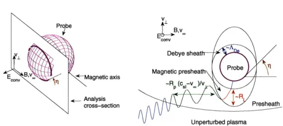
In addition to the sheath and presheath sketched in Fig. (11-2), an intermediate clearly distinct quasineutral region called "magnetic presheath" forms in the regime
ADe
<
RL < R, '. As shown by the ID expansion of Fig. (11-3), the magnetic presheath sets the transition between the presheath where the ions are tied to the magnetic field lines, and the sheath where the ions flow towards the probe.'Note that the space physics community tends to use the term "magnetic presheath" for "presheath"
B
-
-T-
-r-Probe
Diffusive Ion Source
Figure 11-2: Probe sheath and presheath when the ions are strongly magnetized, and cross-field transport modeled as diffusive. In this case no cross-field convective drift exists, hence the plasma at infinity is either stationary, or drifting along the magnetic field lines (from Ref. [4]).
B k
- B
Magnetic Presheath
Solid Surface Debye Sheath
Figure 11-3: Magnetized ion collection by a solid surface in the regime ADe < RL <
R,. The ion Larmor motion is broken in the so-called "magnetic presheath", whose thickness is ~ RL. In the absence of convective electric field, the ions enter the magnetic presheath with a parallel fluid velocity (vj1) = c, and the Debye sheath with a normal fluid velocity |(v) . kj = c,. Note a difference r/2 in the definition of
The Bohm condition at the Debye sheath edge (|(v) . k| = c,) still holds here. Upon considering the variable ( in Eqs (11.7,11.11) as the position along the field lines in the presheath taken from the magnetic presheath edge, it is straightforward to see that the ions enter the magnetic presheath with (v1) = c,. This is the magnetized
Bohm condition in the absence of convective electric field. As for the unmagnetized case, most of the challenge is to solve the presheath equations. The next section discusses the well established isothermal fluid approach to do so, in the context of transverse Mach probe calibration, before proceeding with new kinetic results.
11.2
Foreword on magnetized, transverse Mach probes
II.2.1
The Mach probe concept
Transverse Mach probes [4] are an essential tool to measure plasma fluid velocities close to tokamak separatrix and Scrape-Off Layers (SOL) [17, 18], where ions drift towards the diverter plates at a substantial fraction of the sound speed. The effort is in particular motivated by the need to understand edge sheared flows, thought to reduce turbulence in tokamaks and facilitate the transition from L to H confinement mode [19, 201.
Magnetized Mach probe operation is simple in concept: by comparing the ion saturation current at different angles in the plane of flow and magnetic field, one seeks to measure the external, or unperturbed (intended as in the absence of probe) plasma Mach number M, decomposed into a cross-field component Mi and a free parallel component M,: M Miei + Me 1. In this thesis, Mach numbers are defined as the drift velocity divided by the isothermal ion sound speed: M = vd/cI, where
CI ZTe +Too 1/2(1.0
The most promising probe design is perhaps the so-called Gundestrup [21], character-ized by a set of (at least 3) different electrodes spanning the tip of a single insulating head (see Fig. (11-4)).
(a) (b)
"proud"
collector
graphite
,fus
collector
Figure 11-4: (a) Drawing of the probe on which the term Gundestrup has been coined [21]; twelve tungsten pins span the tip of a cylindrical head. (b) CAD view of the WASP (Wall Actuated Scanning Probe), a four-electrode Gundestrup probe installed in the inner wall of the Alcator C-Mod tokamak [22].
Mach Probe heads perturb the magnetized plasma in a similar way as the flat Langmuir probe shown in Fig. (II-la), and in order to find a theoretical calibration re-lating the ion saturation flux to the different electrodes to the external Mach number, we need to solve the plasma equations in the probe presheath. This requires taking into account one of the cross-field transport effects introduced in paragraph II.1.1.
Upon describing the anomalous cross-field flux as diffusive and in the absence of convective transport, an isothermal fluid formulation of the presheath equations can be solved in the limit of infinite magnetization [23, 24], when the ion motion is one-dimensional because it is constrained by the magnetic field. This provides the theoretical calibration for a Mach probe with electrodes facing parallel and antiparallel to the field, when the flow is field-aligned. This approach, heuristically based on an unknown diffusion rate, proved fruitful because the ion current solution only depends on the ratio of particle to momentum diffusion rates, which was argued to be close to one [25]; the absolute value of the diffusivity only affecting the presheath length. The result is usually expressed by a calibration factor Me, such that the ratio of upstream to downstream ion flux density to the probe for a plasma flowing at isothermal parallel
Mach number M,, is
R ~_ exp .(I.21
For equal particle and momentum diffusivities the model yields Mc ~ 0.41, in agree-ment with Laser Induced Fluorescence (LIF) measureagree-ments [26] to within experimen-tal uncertainty. The kinetic formulation of the same model [27], accounting for the ion thermal dynamics, yields similar calibration factors with slight dependence on the ion to electron temperature ratio at infinity.
In situations where the plasma has a transverse flow component M1, due to strong radial electric fields in tokamaks' edge for instance, diffusion is not required and purely convective equations are more appropriate. The recently solved isothermal fluid formulation of this model [15] predicts for subsonic flows a flux ratio
R = exp( AU - M1 Cot (11.22)
where qp
C
[0 : 7r] is the angle of downfield probe surface to magnetic field in the plane of flow and magnetic field (see Fig. (11-5)). Mc = 1/2 exactly as anticipated in Ref. [25] for the particular case of a semi-infinite probe, but the treatment in Ref. [15] has the remarkable property of being applicable to finite-sized probes of arbitrary convex shape.Because it can also operate as an array of Langmuir probes and measure basic quantities such as temperature, density and potential, the transverse Mach probe is becoming a quasi-routine diagnostic, now starting to be installed in difficult-to-access regions such as the high-field side of the Alcator C-Mod tokamak [22].
II.2.2
General isothermal formulation
It is instructive to discuss the isothermal formulation of the iD magnetized presheath model, by first including several transport terms, and discussing their relative weight afterwards.
B 1| e, and ion cross-field velocity v1 1 ey. In the limit of infinite magnetization
considered here, vi is constant and constrained by its external driver, taken to be a uniform convective electric field in the -e,, direction:
B
vi=En x B2. (II.23)
We further impose the probe to be negatively biased enough for the electrons to be isothermal and Boltzmann distributed (Eq. (11.6)); in dimensionless form;
N, = N. exp </. (11.24)
We only model the quasineutral presheath region where Ni = Ne = N (recall that Nj is the ion charge-density, equal to Z times the ion density), assuming that it extends down to a thin magnetic presheath at the probe surface [4].
We account for cross-field transport through random ion exchange between the perturbed region (or presheath) and the outer plasma, taking place exclusively in the e, direction at a volumetric rate Q [24]. We set Q = Qc + Qa, where Qc and Q, are respectively the classical and anomalous contributions. This is admittedly an over-simplified picture, but models particles and momentum diffusing into and out of the presheath at equal rate, which is consistent with reasonable physical arguments [25] as well as experiments [26). For consistency, we also account for a classical effective parallel momentum collision frequency vc, arising from the same physics as Pc.
Ionization and recombination processes are of complex nature, and as a first ap-proximation we model them by uniform volumetric frequencies v and vRN,, such that the (electron impact) ionization rate is vrN, and the (direct) recombination rate is vRN2; recall that in our quasineutral treatment ion and electron charge-densities are equal. Self-consistency of this simple model requires Vi = vRNO in order for the ion fluid to tend towards its unperturbed state at infinity, which is of course incorrect in SOLs where ionization is balanced by transport rather than recombination. A second self-consistency prerequisite is that background neutrals and ions flow at the same speed.
The ion continuity equation in steady state is therefore
a(N~v)) + v1 0 +v1 (N. - N), (II.25)
OZ y No
and, upon approximating the ions as isothermal, the parallel ion momentum equation becomes Nr (v) mj(v)No Nm (v) + Nmv1 + mv} Q + v1 N (N. - N) OZ Oy No =-N ZT - zT" Oz + mQ (Nxv, - N(v)) + mv1N V N (v} + mNuc (v, - (v)). (11.26)
The left-hand side "Q"-term in Eq. (11.26) originates from particle diffusion into and out of the presheath, while the right-hand side "Q"-term accounts for viscosity. Taking advantage of the Boltzmann distribution of the electrons and substituting the isothermal ion sound speed c81 = [(ZTe + T,) /m]1/2 (Eq. (11.20)) in Eq. (11.26), the
momentum equation simplifies to
0(v) Nv (v) 2 N
N v) + N1 =) -2 ON+ [QNx + (v1" + ve) N] (v, - (v)). (11.27)
Oz _y OZ
Equations (11.25,11.27) are slightly different from what derived in Ref. [28], where neutrals were assumed stationary, ionization and recombination not in balance, and classical collisionality omitted.
The problem geometry, a priori two-dimensional, is shown in Fig. (11-5). The perturbed plasma can be divided into three distinct regions: upfield and downfield presheaths independent of each other, and a shock which we do not need to analyze. In order to go further in the analysis, it is convenient to perform the following change in variables:
-4 Y(II.28)
y I = 1 z - yup]
where u is the cotangent of the angle between the magnetic field and the position vector (fan angle), and w is a normalized distance to the probe along the parallel
direction. The probe coordinates are singular, at u = u, = cot r, and w =
w,
=0. Further normalizing velocities to the isothermal sound speed (M = (v)/cai and M1 = v1
/c
1), Eqs (11.25,11.27) becomeON
+M
w
[O
N
NM]au
au
U - up I m-M p w_
ow
w
(1
+ M1 1+ - (N. - N), (11.29) u-up Q N0N
OM
w
'ON
NM(M^MMl
au
au
U - up law
am
w v1+veM +u
M1No 1+ v+ M (Mm M). -up
No (11.30) Shock (Downstream) Probe -Poeld/d /Downfield Upfield// /y~v Unperturbed regio
iso w
J-
(Upstream)
x
-
z,v,B
ISO
UFigure 11-5: Illustration of the "planar probe" geometry. B and the parallel veloc-ity v are in the e, direction, while the cross field drift vI is along ey. e. is the ignorable axis, but supports the convective electric field. The downfield region can be parametrized by (z, y) or (u, w), where u measures the fan angle cotangent at the origin, and w the parallel distance to the probe.
System (11.29,11.30) is the general formulation of the isothermal strongly magne-tized Mach-probe model, including cross-field transport by classical and anomalous diffusion, convective motion, and accounting for ionization and recombination. Those
last effects involving the ion parent neutral can be considered as cross-field transport mechanisms, since neutrals do not feel the magnetic field hence literally transport charge and momentum in and out of the presheath.
II.2.3
Relative weight of the different transport mechanisms
Let us now estimate the magnitude of the different transport mechanisms in the following sample SOL conditions: pure hydrogen plasma with N = 1019m-3, Te = 30eV, B = 5T, and probe with transverse size Ax = 2mm.
The "e- + H -+ 2e- + H-+" ionization cross section at 30eV is o- = 6.2
10-17cm2 [29], hence (cjve) - aIvte = 2.0 - 10-"mas--1. Similarly the "H + H+ _
H+ + H" charge exchange cross-section at 30eV is o = 260 . 101 7cm2 [29],
yield-ing (acxvj) ~ oczoti = 2.0 . 10-1 4m3 -1. The property (ojve) (o-covj) is typical of hydrogen-like species in the 10 - 200eV range. It is unclear what to choose as ioniza-tion level, since the neutral dynamics in tokamak edges is not fully understood yet. For instance, taking the neutral density to be 104 smaller than the electron density
yields v1 = N(o-ve )/104 ~ ve ~_ 2 0,-1.
In the above discussion we introduced the ion thermal speed
T
defined as the most probable ion velocity in the plasma rest frame. The electron-ion momentum transfer Coulomb collision frequency for an electron with velocity ve and stationary ion target is
Ze2 2 47r
ve = N -3 In A, (11.32)
(47eo m2,e
where ln A ~ 15 is the Coulomb logarithm2, yielding an approximate Maxwellian averaged collision frequency upon replacing ve by vte:
2
Z
2e4167E
mi/
2T2n
(II.33)
2
ln A is the usual notation for the Coulomb logarithm (- In (AD/p9o)), not to be confused with the Debye length AD.
or upon proper averaging over the Maxwellian electron distribution [29]:
e = N 312rs/2 2 Z1/22eT3/24 in A. (11.34)
Momentum conservation then readily yields the ion-electron average momentum transfer collision frequency
e
= Femn,/m ~ 1500s-' for our specific parameters.The classical ion diffusion tensor the ez axis is
D
where
in a coordinate system where B is oriented along
(11.35) DI -Dx 0 (11.36) DI =
mye,
iand upon defining the Hall term
we ZeB
VC mvc (11.37)
the transverse terms can be written
(11.38)
Here v, is the sum of the different classical momentum exchange collision frequency contributions. In our specific example ve = vez + jr ~ , yielding De ~ 2.4P.
10-5m2
S-1. The classical cross-field volumetric exchange rate is therefore
Qc
~ Dc/Ax2 6s-1. Estimating the anomalous cross-field diffusivity as given by theBohm value Dia = Te/(16eB) ~- 0.375m2s 1, the anomalous volumetric exchange
rate is
Qa
~ 6.3 -104s-1.We therefore have the following scaling:
vezT ~ Vf ~ Oc < Vie < Qa,
,I
DL = D II Dx = DI, 3 .
1+#2' 1 +02
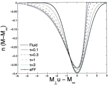
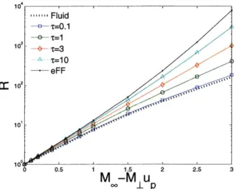


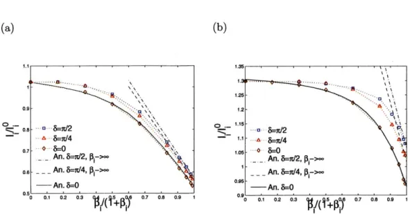
![Figure IV-10: Upstream to downstream flux ratio on the probe major cross-section at (a) rj = 37r/4 and (b) r7 = 7r/4, versus respectively ML + M, and M 1 - M, from a large set of SCEPTIC3D runs spanning Vd E [0 : 2]co](https://thumb-eu.123doks.com/thumbv2/123doknet/14370756.504324/106.918.169.760.145.458/figure-upstream-downstream-section-versus-respectively-sceptic-spanning.webp)
