Publisher’s version / Version de l'éditeur:
Underground Space, 6, 2, pp. 109-113, 1981-09
READ THESE TERMS AND CONDITIONS CAREFULLY BEFORE USING THIS WEBSITE. https://nrc-publications.canada.ca/eng/copyright
Vous avez des questions? Nous pouvons vous aider. Pour communiquer directement avec un auteur, consultez la première page de la revue dans laquelle son article a été publié afin de trouver ses coordonnées. Si vous n’arrivez pas à les repérer, communiquez avec nous à [email protected].
Questions? Contact the NRC Publications Archive team at
[email protected]. If you wish to email the authors directly, please see the first page of the publication for their contact information.
NRC Publications Archive
Archives des publications du CNRC
This publication could be one of several versions: author’s original, accepted manuscript or the publisher’s version. / La version de cette publication peut être l’une des suivantes : la version prépublication de l’auteur, la version acceptée du manuscrit ou la version de l’éditeur.
Access and use of this website and the material on it are subject to the Terms and Conditions set forth at
In-ground energy storage - field test facility
Palmer, J. H. L.; Svec, O. J.
https://publications-cnrc.canada.ca/fra/droits
L’accès à ce site Web et l’utilisation de son contenu sont assujettis aux conditions présentées dans le site LISEZ CES CONDITIONS ATTENTIVEMENT AVANT D’UTILISER CE SITE WEB.
NRC Publications Record / Notice d'Archives des publications de CNRC:
https://nrc-publications.canada.ca/eng/view/object/?id=475bac8b-28d8-4d36-94f1-15f83f6348cf
https://publications-cnrc.canada.ca/fra/voir/objet/?id=475bac8b-28d8-4d36-94f1-15f83f6348cf
Ser
ITH1
N21d
no.
1030
,
c. 2
BLDG
--
National Research
Conseil national
I
#
Council Canada
de recherche Canada
IN-GROUND ENERGY STORAGE
-
FIELD TEST
FACILITY
by
J. H.
L. P a l m e r and
0.
J.
Svec
Reprinted f r o m
Underground Space,
Vol.
6,
1981
p.
109
-
113
L ' i n q u i ' e t u d e a c t u e l l e face a u c o a t c r o i s s a n t e t 3 l a p h u r i e p o s s i b l e dea r e s s o u r c e s h e r g 6 t i q u e s t r a d i t i o n n e L l e s n o u s a m h e 3 nous t o u r n e r d e plus e n p l u s v e r a les sources d l Q n e r g i e r e n o u v e l a b l e . Comlae l a p l u p a r t de ces Bnergies
r e n a u v e l a b l e s d o i v e n t Lcre emmagasin5ea. il e s t e s s e n t i e l d e m e c t r e a u p o i n t d e s s y s t h e s de s t o c k a g e 6conomiques afin d'en t i r e r l e p r o f i t maximum.
C e t a r t i c l e d 6 e r i t une i n s t a l l a t i o n e x p C r i m e n t a l e q u i
permetltra de m e t t r e 3 l ' e s s x i dea u n i t 6 9 d e e t o c k a g e s o u t e r r a f n e e p l e i n e g r a n d e u t . On y t r o u v e kgalement une vut g g n e r e l e des d i v e r s e 6 u n i t e s d e s t o c k a g e , a l l a n t du r e s e r v o i r c l a s s i q u e b i e n i s 0 1 6 au s y s t b e q u i f a i t a p p e l uniquemeat a u s o l non d e r a n g e comme moyen de s t o c k a g e .
RESEARCH
In-ground Energy Storage
-
Field Test Facility
J.H.L. Palmer
O.J.
Svec
Geotechnical Section,
Division of Building Research,
National Research Council of Canada
Ottawa, Ontario
KIA OR6
W Current concern about the cost and potential shortage of
traditional energy supplies has led to an increased interest in renewable energy. To fully utilize most renewable energy sources, however, economical energy storage systems are essential. This article describes a field test facility which will permit tests of full- scale in-ground storage units. The units vary from a classical well- insulated tank to a unit which uses undisturbed ground as the storage medium. Conceptual designs are included.
economical energy storage systems is imperative. In addition, economical storage is a serious concern for conservation schemes seeking to use so-called "waste" heat or to reuse heat in cyclical industrial processes.
Heat can be stored in many modes, the three most common of which are sensible, latent, and chemical reaction heat. This article will be limited to sensible heat storage at low temperatures, i.e., the storage of heat that enters and leaves the reservoir at temperatures below 120°C. Review of current storage schemes revealed that rock and water are the most commonly used materials, and that cost rather than technology is the most important determinant in select- ing a storage scheme.
Various means of reducing costs were studied, the most promising being the use of undisturbed ground as the storage medium, with water as the transport fluid. Subsequently, a novel storage system was conceived and designed. Numerical and laboratory models were tested, a prototype was constructed, and then a field test facility was constructed for the purpose of testing full-scale in-ground storage units. This article describes that facility and outlines the conceptual designs of the storage units, which vary from a classical well- insulated rigid tank to a method of using in-situ soil as the storage medium.
Related studies
Introduction
Throughout history people have built shelters, religious sanctu-Concern about the cost and potential shortage of traditional aries, and storage areas into and under the ground. The mass of soil energy supplies has led to an increased interest in renewable energy. tends to moderate climatic extremes and in essence is a crude form Since the peak energy availability of many renewable energy sources of energy storage. Until recently, however, there has been little does not coincide with peak demand, however, the development of interest in the storage of sensible heat in the soil.
"CLASSICAL" ---"UNDISTURBED" a
I
S o l LI
44
Adhf
QIh ,@i# t4'4a
~.
I
RIGID CONTAINER RIGID CONTAINER
.. . .
..
FULLY INSULATED FULLY INSULATED
FULL OF WATER WATER 8 GRAVEL
.. .
- :FLEXIBLE WALLS FLEXIBLE WALLS
SURFACE SURFACE
INSULATION INSULATION
WATER
ti
GRAVEL WATERa
GRAVELNEST OF HEAT EXCHANGERS RELATIVELY SMALL
EXCAVATION
~ i g ~ . ~ ~ v o l u t i o n of the G r o u n d storage co&ct.
Underground Space, Vol. 6, pp. 109-1 13, 1981 Printed in the U.S.A. All rights reserved.
0362-0565181 1050109-05102.0010 Copyright O 1981, Pergamon Press Lrd.
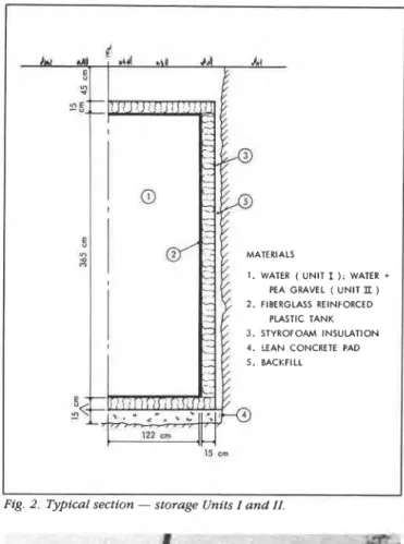
I . WATER ( UNlT I ), WATER +
PEA GRAVEL ( U N l T II )
2 . FIBERGLASS REINFORCED PLASTIC TANK 3. STYROFOAM INSULATION 4. LEAN CONCRETE PAD 5. BACKFILL
15 t m
Fig. 2. Typical section - storage Units I a n d II.
Fig 3. Storage Unit I being lowered into augered hole
110 Underground Space
In 1966 W.B. Edrnondson (1973) first proposed an energy storage scheme that passed heated air through ducts buried beneath a house; he presented this concept again in 1973. It has still not been fully developed, although a solar-assisted house in Saka, Japan, and a greenhouse in Wyoming have successfully employed the same principles.
Shelton (1975) used a simple heat-conduction equation including transient and steady-state behavior to show numerically that sensible heat storage in soil may be feasible. Options for long-term storage of thermal energy were reviewed by Givoni (1977), and two subse- quent papers by Nicholls (1977, 1978) provided a theoretical study of a few proposed ground heat storage systems.
Considerably more effort, both theoretical and practical, has been devoted to using soil as a heat source for heat pumps. A few ground- source heat pumps were developed in Canada in the 1950s (Hooper 1952; Ontario Hydro 1958; West 1959; Brown and Wilson 1963), and there were similar developments in the U.S. and Europe, but the availability of low-cost oil and gas discouraged major effort. Ground- source heat pumps have recently received more attention, as evidenced at the first Nordic Symposium on Earth Heat Pump Systems where papers were invited from scientists in eight European and North American countries. Most of the systems reported on employed horizontally oriented coils or heat exchangers; several
papers, however, recommended vertical heat exchangers as practical I alternatives.
Of particular interest was a paper presented by P.D. Metz, E.A. Kush, and J.W. Andrews (1979) on the solar heat-pump ground- couples storage experiment at Brookhaven National Laboratory. Although this field station was developed independently and is concerned with substantially different experiments, it is very similar conceptually to the one discussed in this article.
Preliminary considerations
When this project began in January 1977, annual storage of hot water in large insulated tanks held little or no promise of becoming economically viable, the major drawbacks being the costs of the tank and construction. Various means of reducing costs were studied and the most promising approach identified was the use of undisturbed ground as the storage medium. The four storage schemes selected for construction (Fig. 1) reflect the transition from a "classical" insulated storage tank to a scheme to use in-situ soil as the storage medium.
Laboratory and numerical modeling were undertaken. Although soil properties can be specified (Kersten 1949), they are site specific and could easily vary by
*
10% from assumed values; consequently, emphasis was placed on behavioral modeling rather than on high accuracy numerical modeling. The laboratory model provided first- level verification of the computer programs. Some of the findings have already been published (Svec 1980) and will not be included in this article. The field experiment, of course, will provide the ultimate test of the numerical models.Field facility
Site selection: Considerations of convenience, security, and con- trol governed the decision to locate the field test facility on the property of the Montreal Road Laboratories of the National Research Council of Canada. The subsoil, of known properties, is commonly called Leda clay, which, because of its very sensitive nature, may create difficult construction conditions. Soil depth to bedrock varies on the site from 8 to 20 m.
Basic Storage Unit I: Conceptually, the basic unit is intended to provide a benchmark of behavior against which construction modifi- cations can be compared; hence, it should be installed with a minimum of soil disturbance. Practically, the unit had to be reasonably easy to handle on site for it had to be installed with available equipment in difficult soil. To achieve easy handling, fiberglass reinforced plastic was selected as the material (Fig. 2). To minimize soil disturbance, the tank was installed in a preaugered hole. Since available equipment restricted the hole to a maximum diameter of 2.9 m, a 2.4-m-diameter tank with a 15-cm exterior layer of extruded styrofoam board insulation was selected (Fig. 3).
Storage Unit II: Identical to Unit I except that it is to be filled with washed river gravel, this unit was used to identify the influence of the gravel fill required for Units 111 and IV (Laboratory tests have indicated that the gravel enhances stratification but does not inhibit convection.) There were no instability problems, and the two 2-9-m- diameter augered holes were drilled and the tanks installed in less than one working day.
Storage Unit
I%:
AS the first major step toward reduced construc- Seprember/Ocrober 1981GROUND SURFACE
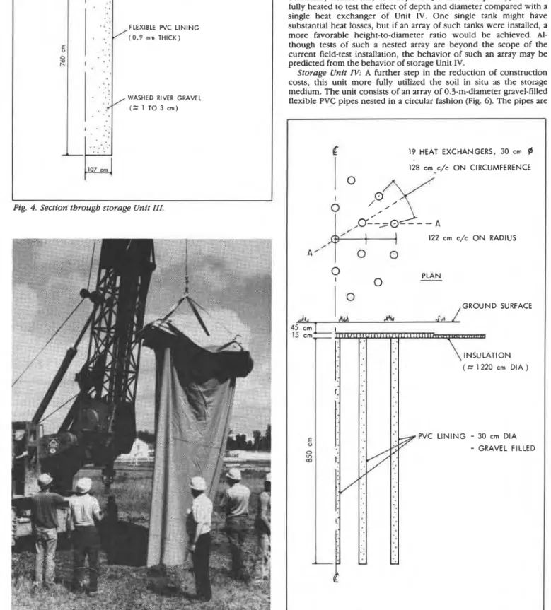
Fig. 4. Section through storage Unit III.
Fig. 5. PVC liner being lowered into augered hole
September/Ocrober 1981
tion costs, the expensive preinsulated rigid tank is replaced in this unit with a flexible PVC liner (Fig. 4), which is filled with gravel and water. The liner was installed in a hole 2.1 m in diameter, 7.6 m deep, which had been augered using a standard caisson drilling machine (Fig. 5). Robinsky and Cormack (1978) have suggested that similar units could be practically constructed to depths of 30 m. Because side and base insulation would be very difficult to install, they were eliminated and replaced by horizontally oriented insula- tion near the ground surface.
Heat losses are anticipated to be substantially greater for this unit compared with Units I and 11. To check this hypothesis, Unit I!I will be initially heated only to a depth of 3.6 m. Subsequently, it will be fully heated to test the effect of depth and diameter compared with a single heat exchanger of Unit IV. One single tank might have substantial heat losses, but if an array of such tanks were installed, a more favorable height-to-diameter ratio would be achieved. Al- though tests of such a nested array are beyond the scope of the current field-test installation, the behavior of such an array may be predicted from the behavior of storage Unit IV.
Storage Unit IV: A further step in the reduction of construction costs, this unit more fully utilized the soil in situ as the storage medium. The unit consists of an array of 0.3-m-diameter gravel-filled flexible PVC pipes nested in a circular fashion (Fig. 6). The pipes are
c
19 HEAT EXCHANGERS, 30 cm @ 128 cm c/c O N CIRCUMFERENCE I 122 cm c/c O N RADIUS / A' GROUND SURFACE INSULATION ( 1220 cm DIA ) -* PVC L I N I N G - 30 cm DIA-
GRAVEL FILLEDFig. 6. Plan a n d section - storage Unit IV.
Fig 7 PVC l i n e r ready f o r installation Fig 8 I n s t a l l a t i o n of PVC l i n e r
fabricated from 0.9 mm thick PVC sheets (Fig. 7) and can be manually installed in holes drilled with a standard rotary drill rig (Fig. 8). Since the amount of soil excavated and the surface area required for installation are relatively small compared with classical storage tanks, this type of storage unit could be installed o n a typical single- family house lot, either during construction or retrofitting. Installa- tion depths of about 20 m are possible with current equipment, making it possible to scale up this unit to a mini-utility sized storage unit.
Several significant concepts have been introduced in this unit, the first being its simplicity of construction. A second consideration is the nested array, making it theoretically possible to selectively charge or discharge the inner and outer rings of tubes - which are, in fact, heat exchangers - s o that high-temperature water may be placed in the center, with low-temperature water in the outer ring serving as a buffer against heat loss. A third concept is the large physical volume of each heat exchanger. Since the thermal conduc- tivity of soil is relatively low, a rapid charge or discharge of the soil cannot be achieved unless there is a large contact surface. The volume of water within each tube represents a reservoir of hot water for a sudden demand, o r conversely, a reservoir to receive a large input of heated water - e.g. from solar collectors during peak daylight hours.
Another advantage introduced in this unit and in storage Unit 111 is the flexible lining. Inevitably some settlement will occur after construction, and there will be some shrinkage of the clay as the soil is heated. The flexible lining will maintain constant contact with the soil, ensuring maximum thermal transfer from the heat exchanger to the undisturbed soil mass.
Supply and control
The four storage units have been installed around a computer trailer and a utility trailer (Fig. 9). Through a heat exchange circuit, each storage unit may be charged individually with hot water supplied by a commercial propane water heater, and each unit may be artificially cooled using a chilled water circuit. If required, interchange between storage units can be used to augment the chiller o r heater capacity.
All monitoring and data reduction will be carried out using a PDP 11-34 computer, located in the computer trailer. Temperature changes will be indicated by approximately 1,000 thermistors, which will be controlled through 200 point scanners, some of which will be located in a remote scanner station. Initially, most of the valve and temperature adjustments will be made manually, but computer control to achieve industrial process, heat pump, and solar applica- tion simulation can be implemented when desired.
Discussion and conclusion
Until hard data have been obtained from the field experiments, firm conclusions would be premature. At this point in the project, however, the use of flexible gravel-filled vertical pipes as heat
exchangers for in-ground storage seems promising. Although the initial test program is directed toward a better understanding of the thermal behavior of in-ground storage units through the storage of hot water, the storage of chilled water for air-conditioning or other process demand will also be considered (the chilled capacity has been adequately sized for this purpose). Chilled water storage units are normally maintained at a temperature close to the natural ground temperature, significantly reducing losses. For similar reasons, one of the most promising applications currently under consideration is the use of the storage unit as a source for a heat pump system during the heating season and as a supply of cool water to meet air-conditioning demand during the summer. If necessary, very simple solar heaters could assist in recharging the thermal storage.
References
Brown, W.G., and Wilson, A.G. 1963 Analysis of the performance of the buried pipe grid of a heat pump. Engineering Institute of Canada, Transac- tions 6 (8-17): paper no. EIC-63-MECH 28.
Edmondson, W B. 1973. The Solterra home. Solar Energy Digest l(5): 1-8. Givoni. B. 1977. Underground long-term storage of solar energy: An overview.
Solar Energy 19:617-623.
Hooper, F,C. 1952. An experimental residential heat pump, Canadian Journal of Technology 30(7/8): 180-197.
Kersten, M.S. 1949 Laboratory research for determination of the thermal properties of soils: Final report. Engineering Experimental Station, Univer-
sity of Minnesota.
Kovach, E.G. 1976. Thermal energy storage. Report of a NATO Science Committee Conference, 1-5 March 1976, at Turnberry, Scotland.
Metz., P.D. et al. 1979. The use of earth coupling on solar assisted heat pumps. In Nordic Symposium on Earth Heat Pump Systems, pp. 11 1-121. 15-16 October 1979, Goteborg, Sweden.
Nicholls, R.L. 1978. Comparisons of deep well and insulated shallow earth storage of solar heat. Solar Energy 20:127-137.
Nicholls, R.L. 1977. Optimal proportioning of an insulated earth cylinder for storage of solar heat. Solar Energy 1 9 7 1 1-714.
Nordic symposium on earth heat pump systems. 1979. Earth Heat Pump Group, Chalmers University of Technology, Goteborg, Sweden, October 15-16, 1979. ISBN 91-7260-340-2.
Orr. J.B. 1977. Wet dirt storage for a solar greenhouse. Solar Energy Digest 9(1):1-3.
Residential heat pump experiments ar Port Credit, 1949-1952 1958. Ontario Hydro Research Division Report No 58-387.
Robinsky, E.I., and Cormack, D.E. 1978. Deep wells for year-round solar heat storage. In Conference on documentation and analysis of improvements in efficiency and performance of HVAC equipment, ASHRAE, pp 197 ff. Shelton, J. 1975. Underground storage of heat in solar heating systems. Solar
Energy 17:132-143
Summer solar energy for winter heating - a small step to ideal solar house. 1976. JARN fJapan Air Conditioning, Heating and Refrigeration News Ltd.), Noven~ber.
Svec, O.J., and Palmer, J.H.L 1980. Heat exchanger for in-ground heat storage. Fundamentals and applications of solar energy, AIchE Symposium series 198, vol. 76, pp. 56-61.
West, G.H 1959. Residential earth-source heat pump, Ontario Hydro Research News, October-December,
This publication i s being d i s t r i b u t e d by the Division of Building R e s e a r c h of the National R e s e a r c h Council of Canada. I t should not be reproduced i n whole o r i n p a r t without p e r m i s s i o n of the original publisher. The Di- vision would be glad to be of a s s i s t a n c e i n obtaining s u c h p e r m i s s i o n .
Publications of the Division m a y b e obtained by m a i l - ing t h e a p p r o p r i a t e r e m i t t a n c e (a Bank, E x p r e s s , o r P o s t Office Money O r d e r , o r a cheque, m a d e payable t o t h e R e c e i v e r G e n e r a l of Canada. c r e d i t NRC) t o the National R e s e a r c h Council of Canada, Ottawa. KIA
OR6.
S t a m p s a r e not acceptable.
A l i s t of allpublicationa of the D i v i s i o n i s available and m a y b e obtained f r o m the Publications Section, Division of Building R e s e a r c h , National R e s e a r c h Council of Canada. Ottawa. KIA