HAL Id: hal-02069490
https://hal.laas.fr/hal-02069490
Submitted on 15 Mar 2019
HAL is a multi-disciplinary open access
archive for the deposit and dissemination of
sci-entific research documents, whether they are
pub-lished or not. The documents may come from
teaching and research institutions in France or
abroad, or from public or private research centers.
L’archive ouverte pluridisciplinaire HAL, est
destinée au dépôt et à la diffusion de documents
scientifiques de niveau recherche, publiés ou non,
émanant des établissements d’enseignement et de
recherche français ou étrangers, des laboratoires
publics ou privés.
UVDAR System for Visual Relative Localization with
application to Leader-Follower Formations of Multirotor
UAVs
Viktor Walter, Nicolas Staub, Antonio Franchi, Martin Saska
To cite this version:
Viktor Walter, Nicolas Staub, Antonio Franchi, Martin Saska. UVDAR System for Visual Relative
Localization with application to Leader-Follower Formations of Multirotor UAVs. IEEE Robotics and
Automation Letters, IEEE 2019, pp.1-1. �10.1109/LRA.2019.2901683�. �hal-02069490�
PREPRINT VERSION. ACCEPTED FO THE IEEE ROBOTICS AND AUTOMATION LETTERS. 2019, FINAL VERSION AT HTTPS://IEEEXPLORE.IEEE.ORG/ 1
UVDAR System for Visual Relative Localization
with application to Leader-Follower Formations of
Multirotor UAVs
Viktor Walter
1, Nicolas Staub
1, Antonio Franchi
2and Martin Saska
1Abstract—A novel onboard relative localization method, based on ultraviolet light, used for real-time control of a leader-follower formation of multirotor UAVs is presented in this paper. A new smart sensor, UVDAR, is employed in an innovative way, which does not require communication and is extremely reliable in real-world conditions. This innovative sensing system exploits UV spectrum and provides relative position and yaw measurements independently of environment conditions such as changing illumination and presence of undesirable light sources and their reflections. The proposed approach exploits this re-trieved information to steer the follower to a given 3D position and orientation relative to the leader, which may be considered as the main building block of any multi-UAV system operating with small mutual distances among team-members. The proposed solution was verified in demanding outdoor conditions, validating usage of UVDAR in real flight scenario and paving the way for further usage of UVDAR for practical multi-UAV formation deployments.
Index Terms—Aerial Systems: Perception and Autonomy, Multi-Robot Systems, Sensor-based Control
I. INTRODUCTION
T
HE growing interest in compact cooperative flights of Unmanned Aerial Vehicles (UAVs) [1] motivates an ongoing pursuit for efficient and embeddable onboard source of mutual relative localization.In our previous work [2], we proposed a novel approach to tackle this issue, relying on vision in the unconventional ultraviolet spectrum. We named this new onboard sensor UVDAR for UltraViolet Direction And Ranging, and together with blinking ultraviolet markers used on its associated targets these comprise the UVDAR system. Its main advantages w.r.t. other solutions are twofold. First, the use of UV significantly increases robustness to challenges of outdoor environments regardless of the time of day, and second, its use of active markers allows for retrieval of orientation or identity of a
Manuscript received: September, 10, 2018; Revised 4, 12, 2018; Accepted February, 5, 2019.
This paper was recommended for publication by Editor Jonathan Roberts upon evaluation of the Associate Editor and Reviewers’ comments. This research was partially supported by the by the Grant Agency of the Czech
Republic under grant no. 17-16900Y, by ANR, Project ANR-17-CE33-0007 MuRoPhen, by CTU grant no. SGS17/187/OHK3/3T/13, by Research Center for Informatics project CZ.02.1.01/0.0/0.0/16 019/0000765 and by project no. DG18P02OVV069 in progmamme NAKI II.
1CTU in Prague, FEE, Department of Cybernetics, Czech Republic
{viktor.walter|nicolas.staub}@fel.cvut.cz [email protected]
2LAAS-CNRS, Universit´e de Toulouse, CNRS, Toulouse, France
Digital Object Identifier (DOI): see top of this page.
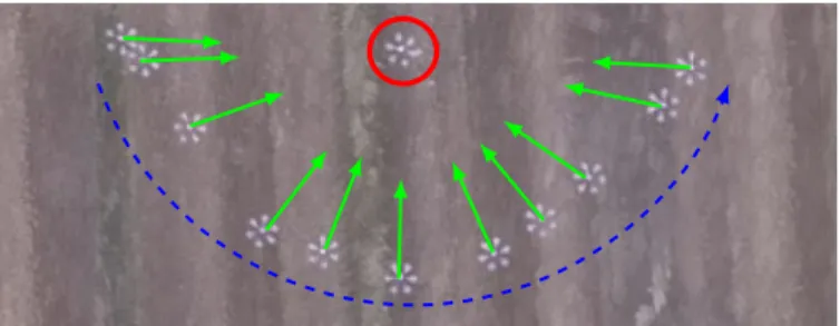
Fig. 1: Top view of a directed leader-follower experiment. The leader rotates by 180 . This is detected by UVDAR sensor carried by the follower, triggering it to create a trajectory as per the proposed algorithm in order to preserve its pose in the leader frame.
target. The availability of such robust sensor is a prerequisite for decentralized outdoor formation flights and swarming and is especially crucial when a sufficiently precise absolute localization source is unavailable, or when it is unfeasible to prepare the necessary infrastructure [3], such as a motion-capture system (MoCap) or a base-station for Real-time kine-matic - Global Navigation Satellite System (RTK-GNSS).
A typical example of multi-UAV flights is the leader-follower formation, consisting of two members, one following the other. Typically, the goal in such flight is for the follower to keep a constant distance from the leader, or to follow its trajectory [4]. Such following is applicable for various tasks such as cooperative mapping of historical buildings, cooperative carrying of objects or cooperative localization of a moving transmitter [3], [5]. In this paper, we show how the leader-follower approach has to be designed to be able to perform the required behavior using the UVDAR sensor. The presented directed leader-follower method, which leverages relative orientation information, can be considered as a guideline for designing complex multi-UAV systems working in real conditions with this sensor.
The literature on classical leader-follower formations is rich, see, e.g., [4], [6], [7] for theoretical works backed by simu-lation. Works addressing the challenges of real experiments are limited, especially relying on onboard relative localization. The experimentally validated approaches often rely on either absolute localization source, e.g., MoCap in [8], or RTK-GNSS in [9], [10]. As is known, MoCap is not practical for real-world deployment (neither outdoor or indoor) as it requires the installation of an expensive infrastructure. The absolute localization sources can provide full pose of the leader to the follower, which oversimplifies the problem.
Fig. 2: Comparison between visible and UV camera footage from UVDAR, collected during the experiment. The UV image is signifi-cantly easier to process to retrieve UAV information.
Even if only partial information is passed to the follower motion controller, like distance or bearing, this type of system provides continuous stream of such information without errors, which is unrepresentative of real-world deployment.
Some more practical approaches consider infrastructure-less sensing, like ranging based on radio signal [11], which only allows for distance-based following without any orientation information. Another approach [12], for the 2D case, wire-lessly communicates the leader intents, which proves feasible since there are less degrees of freedom and less drift than in the presented 3D case. These two approaches rely on radio transmissions, which is subject to the effects of network congestion and interference. This is why we consider vision-based approaches more suitable for the multi-robot groups, especially in uncontrolled outdoor environments.
This direction has been previously explored by the Multi-robot Systems (MRS) group at CTU-Prague, relying on true outdoor relative localization, see [13], [14]. The source of relative localization was an onboard vision-based system using passive circular markers as described in [15]. That came with drawbacks: high sensitivity to lighting conditions and partial occlusion, and substantial size for an acceptable detection range. A similar approach has been proposed [16], that ex-tended the usability of passive markers for low light in short distances by leveraging the infra-red reflection. However, in all other respects it suffers from the same drawbacks as the visible passive marker approach. Furthermore, it was tested only for stable ground vehicles. This motivated the development of the UVDAR system, which is more robust to real-word conditions, due to optically filtering out visual information that is not of interest, reducing the computational load, see Fig. 2 for comparison with visible spectrum. UVDAR also provides relative orientation measurements and target identities, and the whole system is small and lightweight.
Our contribution is threefold. We first show how UVDAR can be used to obtain both the relative position and orientation. We then propose a directed leader-follower algorithm that works interactively with the UVDAR sensor and measurement method. Finally, we validate the performance of the presented method in outdoor experiments.
II. POSERETRIEVALPRINCIPLE FORUVDAR
The UVDAR sensor, presented in our previous work [2] [17], retrieves image positions and
frequency-based IDs for individual blinking ultraviolet markers from a modified camera. This data is used to obtain the relative pose of the leader.
The blinking markers carried by the leader UAV have a known layout. We found that six markers arranged in a pattern of a regular hexagon pose as a good compromise, that ensures that at least two markers are visible from each direction and the markers not being too close to each other. This means that they provide a source of a distance estimation without their images tending to merge in the operational distances. We instantiate this arrangement on a regular hexarotor platform with the markers attached to the ends of its arms, but the arrangement is easily reproduced for any similar rotorcraft, by e.g., mounting the six markers onto a horizontal ring attached to the vehicle. If a different number of markers was to be used, the calculations used in this section need to be adjusted accordingly. In particular, if the arrangement will result in different number of markers being visible from different directions, each case needs separate equations according to the given geometry. The relative yaw is obtained by giving these markers two distinct IDs, retrievable by the UVDAR, one for the three port side markers and another for the three starboard ones. For other shapes of UAVs, different configurations may be preferable, see [17].
In this section we introduce the calculations necessary to retrieve the relative bearing, the mutual distance and the relative yaw when UVDAR system is used in conjunction with regular distribution hexarotors. The relative bearing is the direction towards the leader in the follower body-frame and the mutual distance is the distance between the geometrical centers of the two UAVs. The relative yaw is the angle between the horizontal components of their connecting line and the tailing direction, which is in our case the backwards direction in the leader body-frame.
Note, that for the mutual distance and relative yaw esti-mation we are assuming a horizontal alignment between the sensor and the target, since the height difference has negligible effect on the presented distance estimates and no effect on the relative yaw estimates
Two basic cases of the UVDAR output occur in practice, see Fig. 3, it either sees simultaneously two markers (case A, Fig. 3a) or three markers(case B, Fig. 3b). This depends on the relative yaw of the leader, because of the Lambertian radiation pattern of the markers, leading to two different calculations to retrieve the values of interest. In both cases the distance is first retrieved based on geometrical considerations and then the relative yaw based on marker IDs.
A. Distance Retrieval – case A
The pixel coordinates mi of the origin points (the current
expected image position of a blinking marker obtained by UVDAR, see [2]) is first translated into a 3D unit vector vi
pointing towards the marker,
vi= c2w(mi), (1)
where c2w(·) is a standard function available in a number of vision libraries, such as the OCamCalib toolbox [18], provided that the camera has been properly geometrically calibrated.
Camera α a b lc d
(a) Geometry used when two markers are seen (case A)
Camera γ δ αa αb ϵ a b c lc d ϕ
(b) Geometry used when three markers are seen (case B) Fig. 3: The notation used in relative UAV pose estimation.
As we consider only two markers, the angle their corre-sponding vectors form is denoted ↵ and obtained via cross-product, ↵ = arccos (v1· v2).
This angle is used to calculate the distance lc between the
target UAV geometrical center and the sensor, while presuming that the line segment between the two markers is perpendicular to the line connecting the camera with its center point. This yields lc= ✓d 2 ◆ cot⇣ ↵ 2 ⌘ +p0.75 d , (2) where d is the length of the hexarotor arm, see Fig. 3a.
The relative bearing vector vc, is obtained through the
conversion in (1) applied on the point in between the two origin points visible. The distance lc and vector vc describe
the relative position of the leader w.r.t. the UVDAR sensor. Note that with only two markers visible, there is an ambi-guity on ↵ arising from the simultaneous influence of distance and relative yaw (orthogonality assumption), which is explored in depth in [17]. This ambiguity disappears if three markers are visible.
B. Distance Retrieval – case B
When three markers are visible, see Fig. 3b, the angles ↵a
and ↵bare computed via (1) from two adjacent origin points.
The distance lc and angles ' and ✏ are expressed as
lc= r b2+ d2 2bd cos⇣ +⇡ 3 ⌘ (3) ✏ = arcsin ✓d lc sin⇣ +⇡ 3 ⌘◆ (4) ' = arcsin ✓ b lc sin⇣ +⇡ 3 ⌘◆ . (5)
Here, b and are common terms which correspond respec-tively to the distance from the sensor to the middle marker and the angle formed by the left marker, middle marker and the sensor. They can be expressed as follows
b = d sin(⇡ ( + ↵a)) sin(↵a) and = 2 arctan ✓ P p 3B + 3 ◆ . VI XII III IX II IV X VIII I V XI VII XI IX VII VI
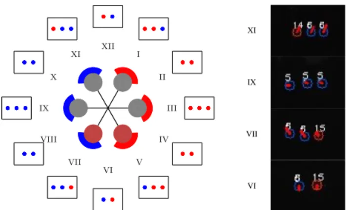
Fig. 4: Left – The layout of the two marker IDs on the considered hexarotor, denoted as blue (6 Hz) and red (15 Hz). Around it the frames illustrate the UVDAR view from their corresponding direc-tion. On the right, the actual view from four different directions from experiments.
The last equation is a compact form of the analytical solution of a set of non-linear equations, where
A = cot(↵a) B = cot(↵b) P = B 2 s O (B2+ 2p3 + 3) 1 ! + 6 s O (p3B + 3)2 ! + (2A +p3) O = A2 AB +p3A + B2+p3B + 3.
The relative position is then estimated from lc and the relative
bearing v2 of the middle marker rotated by ✏ in yaw.
C. Relative Yaw Retrieval – case A
The relative yaw in camera frame cis retrieved from the
IDs of the UVDAR markers. Only a finite number of patterns can be observed, as seen in Fig. 4, which we numbered from I to XII.
When only two origin points are seen, it corresponds to six possible relative orientations. If the two IDs differ, the leader is seen either from the front ( XII and c = ⇡) or
from the back (VI and c = 0), i.e., the tailing direction.
If the IDs are identical, the orientation is ambiguous (II–IV and VII–X). We resolve this with an heuristic, by averaging the two possible interpretations of such observation. Namely,
c =±⇡/3 and ±2⇡/3, so the average is c = ⇡/2 on
starboard side or ⇡/2 on port side. Note, that resolving the ambiguity based on previous observations is precluded by the ability of the target to independently change its rotation rate at any moment.
D. Relative Yaw Retrieval – case B
When three origin points are seen, we consider the other six possible relative orientations, see Fig. 4. They correspond with relative orientation s.t. the follower is roughly facing one specific arm ( e=±(⇡/6 + k(⇡/3)): k 2 {0, 1, 2}).
y x ∆φ ∆z ∆l Follower y x ∆ψ Leader xW yW zW r p
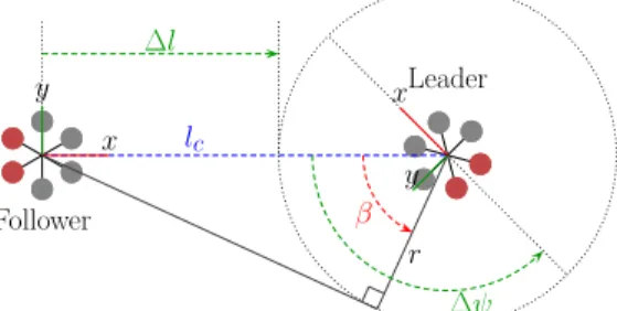
Fig. 5: Variables defining our requirements on the leader-follower system. Red propellers denote the back of the UAV. We want the leader to be on the circular perimeter with the radius r around the leader ( l ! 0) at the height of the leader ( z ! 0), while facing it ( ! 0) from its back ( ! 0).
Imperfect sensor alignment with the corresponding arm is accounted for by using the angle ' obtained from (5) as
c = e '. Note that typically, for the considered
operational distances greater than 5 m the origin points are very close in the UVDAR image, which means that ↵a and
↵b are almost identical, and ✏ and ' had negligible effects.
In both cases, before the information retrieved from the UVDAR, i.e., estimates of the relative position and yaw are used in our directed leader-follower they are transformed into the IMU frame of the follower UAV, which compensates not only for the offset of the sensor but also for the tilt (i.e., roll and pitch) of the unit. Thus corrected relative yaw is denoted as , and is used in the following section as tailing error.
III. DIRECTEDLEADER-FOLLOWER
The goal of directed leader-follower formation is to simulta-neously regulate the mutual distance towards a pre-set tailing distance and to let the follower always face a given leader side (tailing direction), e.g., its back. Our proposed algorithm solves such task and takes also into account constraints of vision-based sensing: 1) forward facing directional sensor and 2) sensitivity to rapid image motion. To address both, the follower behavior is such that it always attempts to face the leader. This guarantees that the leader is in the field of view (FoV) of the sensor and additionally that the leader image position will not change greatly over short periods of time. The requirements of the system are therefore to minimize the control errors illustrated in Fig. 5 as l - the distance error, z - the height error, - the heading error and - the tailing error. These are equal to zero if the follower is in what we call the target pose w.r.t. the leader. The heading error is the horizontal angle between the bearing of the leader and the frontal direction of the follower.
A. Trajectory Generation Strategies
The goal is to steer the follower to the target pose, located on the back of the leader, at a distance r, tailing distance, by which we also define a safety perimeter around the leader.
If the follower is steered only with the currently observed leader pose, changes in the observation lead to rapid changes
Follower Leader (a) Following Follower Leader (b) Orbiting Follower Leader T (c) Flanking Follower Leader (d) Retreating Fig. 6: The four strategies used in our directed leader-follower experiment. The red propellers denote the back of the UAV.
in the follower target pose. This is detrimental as we consider under-actuated platforms which have high coupling between their translational and rotational dynamics. Hence higher trans-lational acceleration means higher tilting, likely to perturb the visual localization. To avoid this, we design the algorithm such that it repeatedly constructs a short-term trajectory, at fixed rate, whose time horizon is at most 4 s. The trajectory consists of isochronous points defined by their position and yaw. Trajectories are naturally constructed in the follower body-frame, if the follower is localized in the world-frame it is possible to convert them to world-frame to accommodate for low-level trajectory trackers.
The trajectory is constructed according to one of four distinct strategies; 1) following, 2) orbiting, 3) flanking, and 4) retreating, as depicted in Fig. 6.
For each strategy we consider the height error and the lateral position errors separately, as the height error does not play into the trajectory selection, and we attempt to bring it to zero as fast as possible in all four cases. We do this, by setting the zcomponent of the whole generated trajectory directly to the zcomponent of the estimated relative position of the leader, which forces our trajectory tracker to reach this height as fast as it can, bringing z close to zero.
The appropriate lateral strategy is selected based on the current situation which is described by the tailing error , the tangential angle = arccos (r/lc) and the distance error
l, see Fig 7. The decision map is as follows:
l < h ! Retreating (6) l2 [0, h] ! Orbiting (7) ( l > 0) ^ (| | < | |) ! Following (8) ( l > 0) ^ (| | | |) ! Flanking (9) where h is a tolerance factor, introduced to prevent rapid switching in boundary cases by creating some hysteresis.
In the following strategy, Fig. 6a, the follower flies directly to the target pose on the perimeter at its maximum admissible horizontal speed.
y x Follower y xLeader lc ∆l β ∆ψ r
Fig. 7: Parameters of the observed situation for strategy selection.
In the orbiting strategy, Fig. 6b, as the follower is already at the tailing distance, it slides along the perimeter to reach the desired tailing direction.
In the flanking strategy, Fig. 6c, the follower flies straight to the tangent point T of the perimeter closer to the target pose, which brings the follower in the orbiting configuration.
In the retreating strategy, Fig. 6d, the follower is inside the safety perimeter of the leader, hence it is navigated outside of it radially, at its maximum admissible horizontal speed.
These strategies are devised to generate a fast path toward the target pose that is continuous up to the first derivative. Generation of each trajectory is based on the measured relative poses of the leader and the follower, from which estimates of the safety perimeter and the target pose lying on it are calculated. Depending on the current strategy, linear, circular or a combined trajectory is generated. The employed sampling of the trajectory ensures that the euclidean distance between two consecutive positions corresponds to the distance traversed at the maximum admissible speed during a single time-step, enforcing constant tangential speed. In order to accommodate for a leader motion, strategy selection and trajectory generation are triggered at a fixed rate.
Additionally, for each strategy we enforce that the follower yaw is such that its camera always faces the estimated leader position, considering the error , by setting the reference yaw in each step of the trajectory to face the currently estimated leader position. This ensures continuous observation without rapid movements in the image as well as preventing loss of the leader from view in case of limited FoV, in our case 180 in the horizontal axis.
The generated trajectories are not accounting for real-world dynamics of the UAV and should be filtered before being sent to the low-level trajectory tracker. In our experimental setup, we leveraged the model predictive control present in our system [19], making the final trajectory smooth. This alters the original trajectory, but the optimization procedure used in [19] minimizes these differences, so that the resulting trajectory differs from the original only in four specific cases. Firstly, at the start of the trajectory after the leader was first discovered, the follower first accelerates to reach the desired tangential speed. This does not happen if the leader was already being tracked, since in such case the initial state already includes the tangential speed. Secondly, if the target pose is reached within a single trajectory generation period, the follower will decel-erate, since abrupt stopping is unfeasible. The third situation
occurs during the transition between the linear and circular phase of the flanking strategy, when the trajectory is adjusted to achieve continuous acceleration. In this case the resulting trajectory resembles turns in automobile roads, eliminating step change in acceleration. This result is possible, because the flanking strategy contains both phases. An additional benefit is that if the next strategy is orbiting, after reaching the perimeter, the initial state will already include appropriate tangential speed so that the original trajectory will be followed with minimal change. Lastly, when retreating the trajectory is set such that the follower retreats according to its maximum speed, without regards to other conditions, which the model predic-tive control interprets by applying the maximum admissible acceleration. As the trajectory is re-generated asynchronously, following one of the four policies, the current state of the model is fused with the new trajectory to ensure a smooth transition. One useful addition for initialization of the leader-follower task or if the leader is lost, is setting the leader-follower to slowly spin in place if it has not detected the leader yet, or has not seen it for pre-defined time.
B. Constraints on the leader motion
In order for the follower not to lose the leader and to prevent collisions, the motion of the leader must conform to a set of restrictions.
The blinking signal retrieval in UVDAR limits the max-imum component of the marker velocity perpendicular to the associated camera optical ray, in order to ensure consis-tent tracking. With our typical frame-rate of approx. 72 Hz, 23 frame signal sample and maximum allowed marker shift between frames of approx. 1 pixel, this limit is 0.3 ⇤ l m s 1,
scaling with the real distance l between the UAVs. The limit also defines the maximum yaw rotation rate of the leader, corresponding to approx. 0.3 ⇤ l/d rad s 1. Additionally,
linearity assumption in the UVDAR [2] limits the maximum acceleration of the leader in this direction to 0.3 ⇤ l m s 2.
While tracking is unaffected by the component of the veloc-ity along the camera optical rays, the distance measurement is less precise than the relative bearing. In particular, earlier experiments [17], showed that in rare conditions the distance measurement error could get close to 20 %.
The distance estimate is important for the follower to suc-cessfully retreat from the leader in case of breached perimeter. This breach must be detected in time despite the distance estimate possible error. In the adverse case where both UAVs are flying directly towards each other, the follower at its following speed of vF max and the leader at vL, the follower
registers a perimeter breach with delay. Additionally, this delay is extended by filtering the distance estimate with a moving average filter of time window ta, when the detection is delayed
by td= ta/2. Note that the detriments of the moving average
filter in this case are balanced by enhanced performance of the bearing estimate. The perimeter breach is detected at the distance
Fig. 8: The UAV platform used in our experiments, here equipped both with a ultraviolet camera (red) and active markers (green) comprising the hardware components of UVDAR system.
where rcollis the collision distance. If aF maxis the maximum
feasible acceleration of the follower in the case of retreating, then collision in the worst case can be avoided if
vL<
p
2lbrakeaF max vF max,
when l < r. In our experimental setting, this translates to limiting the approaching speed to vL < 0.61 m s 1 for
distances smaller than r = 5 m. A violation of this restriction is shown in the red zone of Fig. 10, resulting in the follower not retreating fast enough.
Evidently for greater safety, the leader should avoid ap-proaching the follower. The rough direction in which the follower lies is implicitly known to the leader, since the follower is set to face a specific side of the leader. If the leader needs to fly in this direction, a simple way to prevent approaching the follower is to first rotate, ideally by 90 , and thus to steer the follower out of the way into a relative pose from which it can easily follow in a sideways manner.
Lastly, since the maximum distance for reliable detection by the UVDAR is 15 m, the leader, when it is further than 12.5 mfrom the follower, must not retreat from it faster than vF max m s 1. This will ensure that the error of distance
measurement will not lead to the follower losing the leader from sight. In most cases, the following algorithm already accounts for this, if the following distance is set to less than 12.5 mand enough time is provided for the follower to reach the target pose at the start of the mission.
IV. OUTDOOREXPERIMENTALVALIDATION
A. Experimental Platform
In order to validate the performances of the proposed formation algorithm, we conducted a campaign of real-world outdoor flights with two DJI f550-based hexarotors, see Fig 8. They are each fitted with a Intel NUC7 computer, a PixHawk flight controller and a Tersus GPS receiver, used with a RTK-GNSS system to obtain ground truth.
The two units were each equipped with a part of the UVDAR system. The leader was equipped with ultraviolet markers attached on the ends of its arms. The markers can be set with a blinking ID or not. In our setup two IDs are used as depicted in Fig. 4. Apart from providing IDs, blinking markers ensure robustness against reflections of the sun.
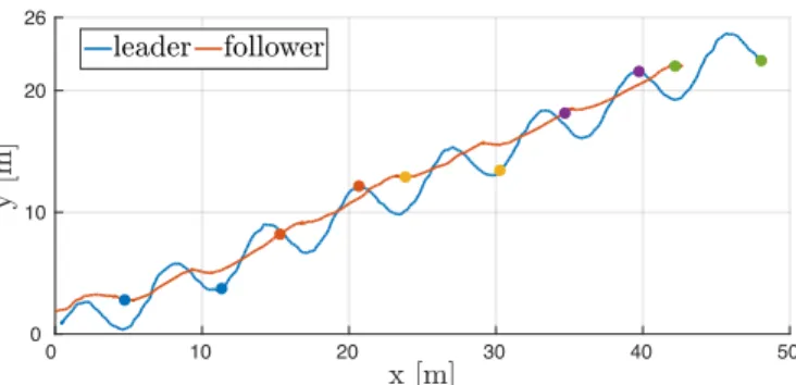
x [m] 0 10 20 30 40 50 y [m ] 0 10 20 26 leader follower
Fig. 9: Top view of the leader and follower trajectories in the preliminary experiment without marker identity. For a sense of time, selected simultaneous positions are marked with the same color.
The follower was equipped with a front facing UVDAR sensor, with a fisheye lens, allowing for 180 of horizontal FoV. Resolution and typical frame-rate are 752 ⇥ 480pix and 72 Hz, respectively. With the current UVDAR settings the detection range is around 15 m, see [17]. The relative positions and yaws of the leader are cyclically estimated at the rate of 10 Hz.
In order to increase the precision and to suppress the effect of any spurious errors of detection on the flight, we use a moving average filter of window 10, on the relative distance and relative yaw estimate. The relative bearing does not need filtering, as it is derived from the image position of the target, which we consider to be sufficiently reliable and precise.
During the experiments we noted that the UVDAR is highly sensitive to the lens focus. Indeed repeated manipulation altering the focus made the detection range drastically decrease to around 6 m, insufficient for practical purposes. Fortunately, focus can be monitored and adjusted easily.
For visualization, comparison and future analysis, the fol-lower also carried a front-facing color camera. The views from the two onboard cameras are recorded a low frame-rate, so as not to impede the UVDAR.
B. Preliminary Flight – Without Marker Identity
In a first set of experiments, we validated the UVDAR performances as a distance and relative bearing sensor, before going further. To do so, a simple leader-follower formation was tested. The markers of the leader were not blinking and the follower set to only approach the leader up to a desired tailing distance. This was implemented as a simple proportional position controller. Such behavior has been demonstrated with various other sensors. The distance and relative bearing are obtained as described in Sec II.
The leader tracked a waving trajectory retreating from the follower, see Fig. 9. The follower successfully managed to tail the leader during the whole trajectory, of length 214 m, demonstrating that UVDAR provides sufficient distance and relative bearing measuring capabilities for real-world flight.
C. Real-World Flight of the Directed Leader-follower Since the UVDAR is also able to provide a useful relative orientation estimate, we have conducted a second real-world
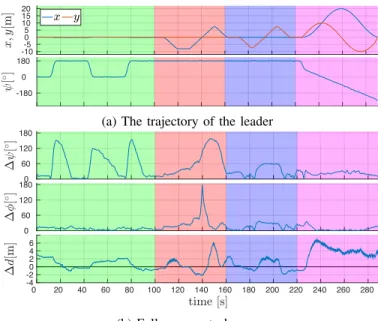
x ;y [m ] -10-5 0 5 10 15 20 x y 0 20 40 60 80 100 120 140 160 180 200 220 240 260 280 A [ /] -180 0 180
(a) The trajectory of the leader
" A [ /] 0 60 120 180 " ? [ /] 0 60 120 180 time [s] 0 20 40 60 80 100 120 140 160 180 200 220 240 260 280 " d [m ] -4 -20 2 4 6
(b) Follower control errors
Fig. 10: (a) The leader trajectory defined by position and yaw . The height was constant, set to 8 m. (b) From top to bottom - tailing error, heading error and distance error. Colored zones correspond to specific leader motions - rapid rotation (green), retreat-approach (red), left-right (blue), and circle following (purple).
flight where this information is used.
The markers on the leader were set to blink, at 6 and 15 Hz following the pattern depicted in Fig. 4. The distance, relative bearing and orientation are obtained as described in Sec II, and used in the directed leader-follower from Sec. III. The tailing distance was set to r = 5 m, with maximum hysteresis h = 2 m. The temporary trajectories are generated at 2 Hz and their tangential speed is a kept at 2 m s 1.
Before the leader started its trajectory, it waited for the follower to reach its target pose. The leader trajectory was devised to highlight the system behavior in four representative cases. First, the leader makes three rapid rotations in yaw by 180 with 30 s of static hovering in between. Second, the leader moves linearly at 0.8 m s 1 with static yaw, going
forward 8 m, backward 16 m and then forward 8 m again. Third, the same retreat-approach motion was performed from left to right. The fourth case was a car-like following of a circular trajectory with a radius of 10 m. The height of the leader was fixed to 8 m for the whole experiment. The leader motion and follower control errors are plotted for the full trajectory, with the four cases, in Fig. 10a.
Video of the experiment can be seen online1and an external
view of the experiment is shown in Fig. 11.
1) Rapid rotation: This highlights the importance and us-age of relative orientation. Every time the follower detected a change in the leader orientation, it flew around the leader, see Fig. 1, to successfully reach the target pose again, demonstrat-ing that relative yaw retrieval with UVDAR is reliable enough for real-world applications.
1http://mrs.felk.cvut.cz/directed-following-with-uvdd
Fig. 11: View of directed leader-follower experiment, the leader (red) is retreating from the follower (green).
2) Retreat-approach: This can be seen as a classical leader-follower formation. The leader-follower uses the relative position estimate to maintain a set distance from the leader.
The observed performance is good overall. However, note that due to the granularity of the distance estimate from vision, combined with observation averaging, the reaction of the follower can be delayed, see Fig. 10b, around the 140 s mark. This engaged the follower collision avoidance mechanism, see [19], forcing it to fly over the follower and then to resume directed following by turning around and orbiting, which is the origin of the observed peak in . This demonstrates that the good following performance can be jeopardized if the leader flies towards the follower faster than the admissible limit of 0.61 m s 1 estimated in III-B, since in
this case we set the speed of approach to 0.8 m s 1. A larger
perimeter can be set to mitigate this, trading off visual distance estimation precision, so a compromise needs to be found for each application.
3) Left-right: When the leader moves side to side, both the relative distance and orientation estimates performances are evaluated. As depicted in Fig. 10b the performances are good as the max. relative yaw was around 60 and the distance error around 2 m, demonstrating that the follower was able to deal with a continuous disturbance in both quantities simultaneously.
4) Circular following: The last part of the trajectory demonstrated the ability of our system to follow a leader along an extended trajectory, by tailing a leader flying along a circular trajectory in a car-like manner. As the plot implies, while the follower lagged behind the tailing distance by 4 m on average, it did not lose track of the leader for the whole trajectory, both in terms of relative yaw and heading.
V. POTENTIALFUTUREEXTENSIONS
The system performances in the experiments validated our approach and more importantly pave the way to a wider use of UVDAR for multi-UAV relative localization.
Other formations can be explored and tested, such as train-like formation where multiple units are following another one in front of them. Thanks to the marker IDs provided by the UVDAR, that can map to leader identities, keeping the leader-follower order should prove easy. Such formation needs to guarantee that leader motion can not force followers further down the line to reach speed or acceleration limits.
Additional studies on leveraging the marker layout are necessary. The current layout, with adjacent triplets of same-ID markers has the drawback that for a pair of same-same-ID (Fig. 4–II,IV,VIII,X), the relative yaw is ambiguous, e.g., II and IV appear identical. In Sec. II-D we used a heuristic, averaging the two possible interpretations. Another available option is presuming one of the two interpretations based on which leads to the more favorable dynamics. With the current layout, leader starboard and port directions (III and IX) can not be chosen as alternative tailing directions since they are surrounded by ambiguous observations.
However, with the current layout it is possible to steer a follower to any of the other alternative tailing directions that can be uniquely located (Fig. 4-V,VI,VII,XII,XI,I). This allows for multiple directed followers for a single leader, separated by different tailing directions. A simpler way to allow for more followers is to assign them to different relative heights, although the aerodynamic coupling between the followers must be taken into account in that case.
For steering towards one of the unique positions the current layout was sufficient, but for truly arbitrary static formations a third identity must be introduced, using up more of the limited number of available IDs.
Filtering distance estimation with simple averaging proved to be a weak point, imposing strong motion restriction on the leader, and more advanced filtering techniques, such as a Kalman filter, should be considered in the future.
VI. CONCLUSION
In this paper, we demonstrated the applicability of our novel vision-based relative localization system UVDAR for cooperative UAV flights on a specific implementation of the leader-follower formation. This directed leader-follower formation control exploited the relative leader pose obtained by the UVDAR sensor, comprising position and yaw, to steer the follower to a target pose pose w.r.t. the body of a moving leader, while also preserving the conditions for continued observation by this vision system. The cooperative combination of UVDAR with a specialized control algorithm was shown to maintain the desired following behavior, without direct communication between the two UAVs.
The encouraging performance of the system for various motions is shown through outdoor experiments. In particular, the use of UVDAR for a real application is demonstrated for the first time, in demanding outdoor situations. More complex formations have to be addressed in future work. Overall, the UVDAR performance in outdoor conditions should lead to its wider adoption.
REFERENCES
[1] S. Chung, A. A. Paranjape, P. Dames, S. Shen, and V. Kumar, “A survey on aerial swarm robotics,” IEEE Transactions on Robotics, vol. 34, no. 4, pp. 837–855, Aug 2018.
[2] V. Walter, N.Staub, M. Saska, and A. Franchi, “Mutual localization of uavs based on blinking ultraviolet markers and 3d time-position hough transform,” in (CASE 2018), 2018.
[3] M. Saska, V. Kratk´y, V. Spurn´y, and T. B´aˇca, “Documentation of dark areas of large historical buildings by a formation of unmanned aerial vehicles using model predictive control.” in ETFA. IEEE, 2017.
[4] Y. Zou and Z. Meng, “Leader-follower formation control of multiple vertical takeoff and landing uavs: Distributed estimator design and accurate trajectory tracking,” in (ICCA 2017), July 2017, pp. 764–769. [5] M. Saska, “Large sensors with adaptive shape realised by selfstabilised compact groups of micro aerial vehicles,” in International Symposium on Robotic Research, 2017.
[6] A. S. Brando, I. H. B. Pizetta, M. Sarcinelli-Filho, and R. Carelli, “High-level nonlinear underactuated controller for a leader-follower formation involving a miniature helicopter and a ground robot,” in (SBR-LARS 2012), Oct 2012, pp. 168–173.
[7] J. Choi and Y. Kim, “Fuel efficient three dimensional controller for leader-follower uav formation flight,” in (ICCAS 2007), Oct 2007, pp. 806–811.
[8] D. A. Mercado, R. Castro, and R. Lozano, “Quadrotors flight formation control using a leader-follower approach,” in (ECC 2013), July 2013, pp. 3858–3863.
[9] S. Montenegro, Q. Ali, and N. Gageik, “A review on distributed control of cooperating mini uavs,” 2015.
[10] J. Vilca, L. Adouane, and Y. Mezouar, “Adaptive leader-follower forma-tion in cluttered environment using dynamic target reconfiguraforma-tion,” in Distributed Autonomous Robotic Systems, 2016, pp. 237–254. [11] T. Chen, Q. Gao, and M. Guo, “An improved multiple uavs cooperative
flight algorithm based on leader follower strategy,” in (CCDSC), June 2018, pp. 165–169.
[12] T. Bhavana, M. Nithya, and M. Rajesh, “Leader-follower co-ordination of multiple robots with obstacle avoidance,” in (SmartTechCon 2017), Aug 2017, pp. 613–617.
[13] M. Saska, T. B´aˇca, J. Thomas, J. Chudoba, L. Preucil, T. Krajn´ık, J. Faigl, G. Loianno, and V. Kumar, “System for deployment of groups of unmanned micro aerial vehicles in gps-denied environments using onboard visual relative localization,” Autonomous Robots, vol. 41, no. 4, pp. 919–944, 2017.
[14] V. Spurn´y, T. B´aˇca, and M. Saska, “Complex manoeuvres of heteroge-neous mav-ugv formations using a model predictive control,” in (MMAR 2016). IEEE, 2016, pp. 998–1003.
[15] T. Krajn´ık, M. Nitsche, J. Faigl, P. Vanˇek, M. Saska, L. Pˇreuˇcil, T. Duckett, and M. Mejail, “A practical multirobot localization system,” Journal of Intelligent & Robotic Systems, vol. 76, no. 3-4, pp. 539–562, 2014.
[16] H. Park, I. Choi, S. Park, and J. Choi, “Leader-follower formation control using infrared camera with reflective tag,” in (URAI 2013), Oct 2013, pp. 321–324.
[17] V. Walter, M. Saska, and A. Franchi, “Fast mutual relative localization of uavs using ultraviolet led markers,” in (ICUAS 2018), 2018. [18] D. Scaramuzza, A. Martinelli, and R. Siegwart, “A flexible technique for
accurate omnidirectional camera calibration and structure from motion,” in (ICVS’06), 2006.
[19] T. Baca, D. Hert, G. Loianno, M. Saska, and V. Kumar, “Model predictive trajectory tracking and collision avoidance for reliable outdoor deployment of unmanned aerial vehicles,” in (IROS 2018). IEEE, 2018.