PFC/JA-84-13
Constraints on Very High Beta Tandem Mirror Reactor Operation
R.E. Potok
Plasma Fusion Center
Massachusetts Institute of Technology Cambridge, MA 02139
Abstract
There are several tandem mirror schemes which propose a very high 0 and edge stabilization for the center cell plasma
(13
being the ratio of plasma pressure to the vacuum magnetic field pressure). While the exact criteria for the edge stabilization are uncertain, it is possible to analyze the option space in which a very high 0 mirror reactor would operate. The primary constraints on such a reactor are the energy balance at ignition, the build-up of He4ash and the hot, a-particle f
(4?
"), and the need for abiabatic conservation of the ion gyro-orbits in the axial and radial field gradients. These constraints limit reactor operation to a very low plasma field regime (B,, ~ .6 Tesla), and require that the plasma edge have near classical thermal conductivity.Introduction
This paper presents an analysis of an axisymmetric tandem mirror with a very high center cell 3. Curvature driven modes (interchange, ballooning, and trapped particle modes) are assumed to be stabilized at the plasma edge. There have been several proposals made in recent years which would stabilize these modes at the plasma edge. They are a cusp geometry [1], ponderomotive stabilization
[2],
or a conducting first wall in the bad curvature regions[3]. Additionally, the edge might be stabilized external to the center cell by properly shaping the radial profile of the plasma in the end cells. The edge stabilization methods result in a much higher thermal transport in the plasma interior than in the plasma edge region, either due to anomalous processes such as drift instabilities (a maximum iBZ mirror will not support a plasma pressure gradient away from the plasma edge), or due to the very high 8 in the plasma interior resulting in large classical transport (the classical transport scales inversely with the square of the plasma reduced magnetic field). The large interior transport results in a square pressure profile in the center cell (with the pressure gradient localized at the edge). This can be thought of as an ideal case in that the square profile maintains a constant 3 radially and thus provides the maximum total plasma energy density in the center cell (for fixed constraints on 3 and the magnetic field).This paper analyses the compatibility of edge confinement scaling with the engineering and economic requirements of a commercial tandem mirror reactor: attractive wall loading and total thermal power, low recirculating power, and an economic plant capital cost. One of the primary expectations is a huge savings in the cost of the reactor magnet system. Because of the high
/,
the center cell magnet field B, is expected to be considerably less than the 4.7 Tesla of the MARS design[41,
which relied on a minimum-B anchor cell to provide average good curvature to the magnetic configuration. Due to the edge stabilization criteria, the plasma radius is expected tobe larger than the .49 m of the MARS design. resulting. with a similar wall loading and total thermal power, in a much shorter center cell length for the high 3 reactor. The shorter, lower field configuration should result in significantly less support structure and amp-meters of conductor. In addition. the end cell geometry is very simple. compared to the MARS design. Because the anchor cell and associated transition coils are not needed, the entire magnetic configuration of the high 3 reactor can be axi-symmetric. This is one of the most attractive features of the high 3 reactor. The entire end cell geometry consists of an axi-symmetric plug cell followed by a direct conversion cell. The end cell magnet costs of the high 3 reactor are expected to be much lower than the MARS end cell magnet costs.
A clear analysis of the viability of the high 3 reactor can not be made, due to the uncertainly of the stability criteria at high 3. This paper does present, however, parametric scans of the available option space. which is limited by several physical constraints related to the ignition criteria, and by economic limits on the power cycle. We will determine the parameters that must be present at the edge in order for the high 3 reactor to operate in an economical regime. These parameters may involve the minimum plasma 3 required for edge stabilization, and the radial thickness of the stabilized plasma edge. Future work will determine if these parameters can actually be achieved.
Confinement Time Scaling with Edge Stabilization
In this paper. it is assumed that the interior of the plasma has a high thermal conductivity, and hence cannot support a pressure gradient in the radial direction. Only the edge region has a low enough thermal conductivity that can support a pressure gradient. The confinement of such a system is analogous to a container of gas in a vacuum, with the container's wall consisting of a porous membrane. Assume the container is a cylinder of radius r and height h. Also assume that the material at the two ends is non-porous. so that all the diffusion is radial, and that the porous membrane of the cylinder has a diffusivity D. The porous area is thus 2irrh, and the flux
(F) through the porous membrane is:
-Dn N irr2
hii
rnF=-DVn = r -- =- {f}
br Area 27rrh 2
where n is the density of particles in the container. N is the total number of particles in the container.
n
and N correspond to the flow rates per unit time, and 6r is the radial thickness of the membrane. The particle confinement time (7-P) can be expressed as:n rbr{}
TP = =2
Note that the confinement time scales linearly with br, even through the diffusion time through the membrane alone would be proportional to (6r)2.
With respect to the high 8 plasma, the diffusion constant D can be replaced with an expression relating to the energy and particle transport rates in the edge region. These terms are expressed
as arbitrary multiples of the classical ion thermal conductivity, which is: cnuto" ~ o,, /2,
where p, is the ion gyro-radius and v,, is the ion-ion collision frequency. The factor of two is an estimate of the decrease in the energy transport due to the momentum conservation involved in the collision process of ions with similar mass. (In a Lorentzian regime, (with the background particle's having infinite mass), the classical conductivity would be p2v,,). The effective energy and particle confinement times (re and r,) are defined as:
rS r
e =
{3}
(M - + M;)p2v,{
M. ={4}
where M' is a scaling factor representing the effective heat conduction coefficient, and M; is a scaling factor representing the effective particle loss rate. From strictly classical considerations, M. would be much less than one, since the ion particle diffusion would occur on the ion-electron collision time scale, since like-particle collisions produce no net particle transport. In practice, due somewhat to deuterons and tritons having different masses, but primarily due to anomalous transport, the particle transport rates are expected to be at least as fast as the classical heat conduction rates. Indeed, it will be shown later in this paper that such values of particle transport are necessary in order to purge the plasma of helium ash, the burn product of the DT fusion.
Energy Balance at Ignition
In a steady state ignited plasma, the energy deposited in the plasma by the hot
a-particles
equals the energy loss rate due to particle loss, energy conduction, and radiation. In this paper, the scaling factors M' and M; represent these processes in the expression for a effective energy confinement time. The volumetric heat generation rate (q'".) can be expressed as:
M E nkhT
q" - C- CPd {5}
where kbT represents the plasma temperature (in Joules), the sum is over all particle species, Pd is the a-particle power density from the fusing DT, and C, is the percentage of a-particles that are confined by the magnetic configuration. The energy density of the plasma can be written as:
r rC, Pdo #to, B2
nkT - 2 "_6} f
P Vi (M- + M;) 2po
where 3tot is the total plasma
f,
and B /2pu,, is the vacuum magnetic field pressure.For the rest of this paper, SI units of measurement are used, except for plasma temperature
T, which is expressed in keV, and for wall loading WL, which is expressed in MW/M 2
.
For the DT ion mixture, an average mass was used of 4.17 x 10⁻² kg. With this approximation, the term p,vi, averaged over both species, can be written as:
p2 vii = 1.47 x 10⁻²¹ nDT {7}
VIT(B2) edge
where (B2)edge is the average B2 along an ion orbit as the ion is diffusing through the edge region.
I
now define the symbols a, to be the plasma radius in which the pressure profile is flat (that is, inside the edge region), a+ is the outer radius of the plasma (including the edge region), and a, is the radius of the first wall. I assume that an average particle will drift half-way into the edge region (in the radial direction), before becoming axially unconfined. This radial position is labelled a,+6a,, with a,+26a
=a+
. The average field along the average particle drift though the edge is approximated by the field at a.+ 6a,/2.
Assuming a long, thin equilibrium and s plasma pressure profile that linearly decreases to zero from a, to a+, the average B2 along the ion orbit can be expressed as:(B2)edge = B2(1 - .75#hot) {8}
The
a-particle
power density can be written as:P" = .25n2,(aV)Q, = 9.38 x 10⁻³"n2 /T {9}
where
Q
= 5.64 x 10 1 3 Joules/fusion {10}(uv) velocity averaged DT fusion cross section = 6.653 x 10⁻² 2
m 3/sec for T 30 keV {11}
T _-(ov)
(T
= 30 keV) {12}(uv)
The energy balance equation at ignition can thus be written as:
a,6aConDT - 6.24 x 10¹⁸#tt (M* + M;)T IT(1 - .75#ht)
Alpha Particle Confinement
In very high 0 operation, the magnetic field gradient in the edge region will be large, and hot a-particles which enter the edge region will not conserve their gyro-motion adiabatically. These particles will scatter in pitch angle space in a time much shorter than the slowing down time, and leave the system when they scatter into the velocity space loss cone. The percentage of a-particle power confinement is therefore approximated by the percentage of a-a-particle orbits that lie within a.. For this analysis, all a-particles are conservatively assumed to be created with 3.51 MeV of rotational energy. The approximation is made that this assumption is balanced by other loss channels of the a-particles, namely a-particles created in the loss cone and a-particles that scatter into the loss cone before slowing down. In order for the plasma to be ignited, the assumption must be made that the hot a-particles with orbits that lie within a, are radially confined in the plasma interior during their slowing down time. An a-particle with 3.51 MeV of rotational energy will have a gyro-radius p* of .27/B,, where B, is the 8 reduced plasma magnetic field. An expression for C, can now be written as:
\ , \ 2
COI (-P~
~
- {14}Wall Loading and Impurity Build-up
The neutron wall loading (WL.) can be written as:
Pnirap2 a a WL,, = P = 1.88 x 10-40 PnDT ap {15} 27a,, T a, where Pd" = .25n2D,(t-v)Q"
{16}
Q
= 2.26 x 10⁻¹⁸ MJ/fusion {17}Defining
f
a,/a+, the energy balance equation can now be written as:.27
21 - fa,
T3/2 1.47B023Dr/t~ t S -WL, {18} P ,o 1 - tat, 2f a, M , + M I - .75)3tot where fO T = 8.05 x 10 2 2nDTT/B2 {19} ±t t = 'a, +#'{
20}Throughout this paper, 6 for each ion species represents both the ion pressure and the thermal pressure of the electrons associated with that ion species. Thus, the ratio of helium ash to the n,, can be written as:
nw' (burn fraction) C, .6667#3" _ ___ __ ____
~
____ -{21} nDT 2 T in where .25n 20t) burn fraction = .25n 2 DT/(T) {22} .25nI .()+ nIT/ 2,r,)Hot Alpha Particle Pressure
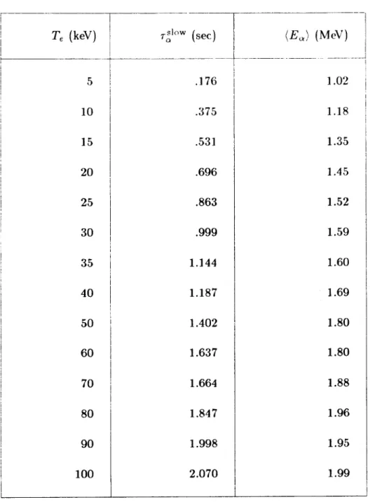
Table
I
presents data on the slowing down time of hot a-particles as a function of the electron temperature. This data was used to produce the following approximation for the a-particle slowing down time in the regime of 20 keV < T, < 60 keV:slow _ 6.6 x 101 8T -8
n,
+
2ny'2 The density of hot a-particles can thus be written as:n'" = .25n,-r(uv)Corf"O
{
24}nr _ n., .0011CT-8
{25}
nDT nDT+ 2nyh
T
The regime of 20 keV < T,
5
60 keV encloses the option space in which the high#
mirror reactorcould operate. Temperatures much below 20 keV would produce a very collisional plasma, and lead to large end-cell recirculating power due to the high trapping currents. Temperatures above
60 keV would result in very large potential plug and thermal barrier depths for the plug cell. For
the regime of 20 keV < Te < 60 keV, the average temperature of a hot a-particle, averaged with
the associated two thermal electrons, was estimated to be 550 keV. The equation for 63;"' becomes:
13", 3n;"' 550 keV
P3DT 2 nDT T 16
#2
/T.91C
9C{27}
Radial Adiabatic Constraints
The plasma
#
can be written as a function of plasma radius r:#tot, if r < a,;
3(r)
j#tot
I - r2a, , if a, r < a- .28}The approximation has been made previously that the average DT ion diffusing through the edge region will be axially unconfined when it is at a radius of ap
+ ba,.
The average magnetic field gradient along the particle orbit as it diffuses from ap toba,
is approximated by the field gradient at a.+ ba,/2.
From the equation{28},
this gradient can be written as:1dBB 1 /3tot
I B - to29} {
B dr lr=a,+bai,/2 46a (1 - .75#tot)
As the DT ions are diffusing through the edge region, the magnetic field gradient must be small enough that the ions have adiabatic gyro-orbits. The quantity AB/B should be small over a radial distance of 2p', the radial distance spanned by orbiting ions. I define a radial adiabatic goodness parameter Er to be
a, { 30}
B Xr
For adiabatic conversation of the particle orbits in the edge region, E, should be < .25.
Axial Adiabatic Constraints
The dominant constraint on the axial magnetic field gradient is the requirement that the hot a-particles must be adiabatically reflected at the ends of the center cell. A hot a-particle with mostly parallel energy can travel 2xpo in the axial direction in a gyro-orbit time
(remember
pt hasbeen defined as the gyro-radius of a hot a-particle having all rotational energy). For a fixed axial adibatic goodness parameter E,,, this constraint can be seen as a relationship between the plasma field B and the axial distance in which the center cell field is ramped up to the choke coil field.
z = .25 = B t 49z {31}
B 9z
Substituting .27/B for po, we have:
9B _B 2
-B - B(z) = -7/z {32}
(9z 7
The minimum axial distance needed to ramp the magnetic field at each end of the center cell can thus be approximated by:
7 7
AZraMP -
{
33}For example, if the plasma magnetic field were 1 Tesla., approximately 7 meters of axial distance would be required to ramp the field into the choke coil. If the plasma field were .7 Tesla, 10 meters would be needed. The wall stabilization criteria may place additional constraints on the profile and ramping distance of the magnetic field at the center cell end, in order that the bad curvature regions be wall stabilized. These criteria are at present not understood for the high 0 regime.
Solution Procedure
A basic energy balance (equation {18}) has been developed for the high 0 tandem mirror
reactor. The attractiveness of the reactor is somewhat difficult to evaluate, due to the lack of a theoretical understanding of the stability constraints at high #. In particular, the radial thickness of the stable edge region and the theoretical constaints on /3 are unknown., and the attractiveness of the reactor can only be expressed as functions of f and / (f = a,,/a-t). An evaluation of the feasibility of the reactor must await the understanding of what f and .3 values are necessary for stability.
Self-consistent solutions to the energy balance equation were found in the following manner: First, values were chosen for M-, E,
f,
#tot, T (which defined T), ar/ae, and B,. Then, an initial guess was made for 0,D. Given these parameters, the other values could be determined:1. I3D, T, and B, determine nDT
2. equation {29} determines ba,
3. ba, and f determine a,
4. equation {14} determines C0
5. equation {15} determines WLn 6. equation {18} determines M,
7. equation {21} determines /3 8. equation {27} determines /3'
Once these quantities are calculated, the initial choice of 0,D is compared with the value of
Results
The following parameters were chosen for the first series of parameter studies:
M
1,f=
.85,a,/a,, = 1.2, B, = 2.5 Tesla, and , = .25. The choices for
f
and a /a, result in approximately 6 cm of vacuum between a4 and a,,. The choice off
results in %(a,)/%(a") ~ .3, where %J(r) is the enclosed axial flux at radius r. It will be shown that .(a,)/'(a) ~ .3 is a practical limit for the high0
reactor, due to constraints on wall loading and particle confinement scaling (larger values off
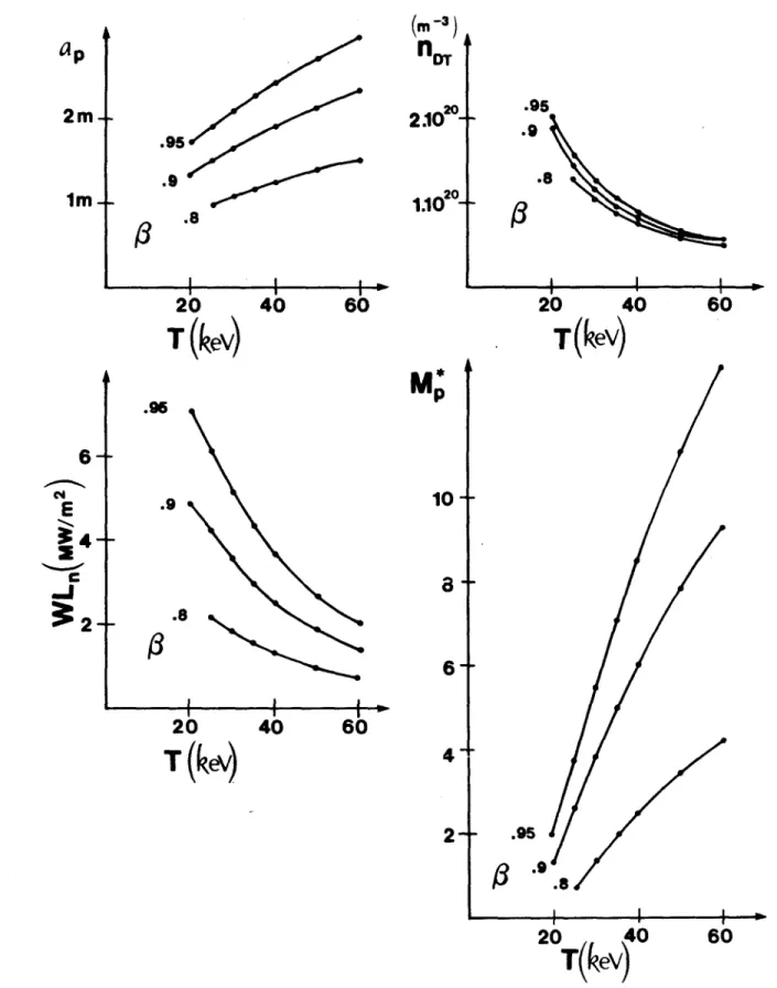
result, in unacceptably large wall loading).For the above mentioned initial parameters, a parametric scan was made of the ignition point for different values of T and )tot. The data from this scan are shown in Figure 1, where a,, nDT, WL,, and M; are plotted as functions of T and 3tot. One can see the strong dependence of WL,
and
M'
on both T and#tot.
At first, it seems desirable to operate the reactor at very high T (40 to 60 keV), in order to reduce the wall loading to managable levels, and increase M,*, which can be viewed as a margin of ignition. What is not incorporated into this analysis, however, is the recirculating power and potential profiles of the end cells. Given that the thermal barrier potential is 3 to 5 times the center cell electron temperature Te, an increase in Te will result in larger radial electric fields in the end cells, and it is unclear how detrimental these fields will be to the confinement of the passing distribution, and to the global energy balance of the reactor. It does appear from Figure 1, however, that, forfitot
= .9, the plasma temperature must be at least 40 keV in order keep the neutron wall loading less than 5 MW/M 2.Figure 2 shows an alternative regime, where the radial adiabatic constraint has been relaxed. The value of E, has been increased from .25 to .33 . The main effect has been to lower the wall loading (by about 20%, averaged over parameter space), but also to substantially lower the ignition margin M,;. For a base operating point at T = 30 keV and 3t3t = .9, the wall loading is reduced from 6.9 MW/M 2 to 5.5
MW/M 2, but M also is reduced from 3.8 to 1.1 . It is probably too optimistic to assume an actual value of M' that close to the classical conduction conductivity, in which case the parameters in Figure 2 would represent a regime far below the ignition criteria. The same effect can be seen in Figure 3, where E, has been re-set at .25, but
f
has been reduced to .8 . The base operating point again has lower values for neutron wall loading and M,*. At the base operating point, M; = 1.6, and WL, = 4.9 MW/iM2. The conclusion is that Er and f both serve a dual purpose. Er < .25 is necessary to conserve adiabatically the gyro-orbits of the ions. A high
f
may be necessary in a wall stabilization scheme[3]
in order to bring the high plasma pressure close to the conducting wall so that the m = I curvature driven plasma modes can be stabilizedby image currents. We see from Figures 2 and 3 that the base values for
f
(.85) and "E (.25) are also necessary to allow for some margin of ignition above purely classical values for the T ~ 30 keV regime.Figure 4 shows a parametric scan in which the vacuum field B, has been increased to
3
Tesla. It shows that the wall loading can be increased from the B, = 2.5 Tesla regime without effecting the margin of ignition M;. This scaling relationship leads to a feasible operating point for a moderate center cell temperature T, which is shown in Figure 5. In this case, the vacuum magnetic field has been reduced to 2 Tesla. For 3 = .9 and T = 30 keV, this results in an attractive neutron wall loading of 3.5 MW/m 2, similar to the MARS design [4]. The characteristics of a highP
reactor at this operating point are shown in Table II. A lower limit of 2 Tesla was chosen for B", due to the axial constraints on the axial magnetic field gradients. With a plasma field on the order of .6 Tesla, the minimum ramp distance for the center cell field into the choke coil is over 10 meters. Due to the physical sizes of the choke coils, the ramping distance for the last few axial meters is set by the radius of curvature the choke coil is capable of generating, and thus the minimum ramping distance at each end of the base design is probably on the order of 15 meters. Given the desirability of having the thermal power of the reactor below 3000 MW, the two ramps take up most of the axial length of the center cell (f,). Details of the edge stabilization mechanism, in particular the local plasma 8 and the gradients of the field curvature along the ramp, were not considered, and may place additional constraints on the ramping distance.Assuming the B, = 2 Tesla regime were feasible, it is interesting to compare the capital costs and recirculating power of MARS and the reactor described in Table II. The two reactors have the same wall loading and thermal power (and hence the same first wall area), the blanket costs are expected to be comparable. The high
f
reactor may allow more freedom in the design of the LiPb coolant flow paths, due to the reduced magnetic fields (B, = 4.7 Tesla for MARS). There is a very substantial savings for the high 0 reactor in the cost of the center cell magnets. Assuming thatthe current centroid for the solenoidal magnets is at am = a + 1.4 m, and that the capital cost
of the magnets scales as ea, B,, the cost of the high 0 reactor center cell magents would be 20% of the cost of the MARS center cell magnets. Considerable savings would also occur in the end cell magnet system, because of the simple end cell geometry of the high
#
system. If the curvature driven modes are stabilized by a conducting wall or by ponderomotive forces, a minimum- B anchor cell would in principle not be needed, nor the transition coils which map the flux into the anchor. The high 3 reactor could have an axi-symmetric plug cell containing the electron thermal barrier and ion plugging potential, following directly by the direct conversion cell. The entire magneticconfiguration could be axisymmetric, depending on the optimal design of the direct conversion cell. Averaged over the plasma cross section, the high 0 reactor described in Table 1I has ap-proximately half the density as MARS, while the enclosed flux at the plasma edge (kP(a,)). is approximately double that of MARS. Assuming the same peak choke coil field for MARS and the
high 3 reactor., and that the source of particles from the center cell that must be plugged is
pro-portional to %'(ar,) n, it appears that the two reactors have similar plugging and particle pumping requirements. If these terms dominate the recirculating power requirements, the two reactor may be similar in their recirculating power. If the end cell magnetic geometry is important in determin-ing the recirculatdetermin-ing power. the two reactors may have quite different requirements. The high
#
reactor has a smaller end cell plasma volume, axisymmetric fields which imply better radial confine-ment, and no MHD anchor neutral beam requirements. These factors will lower the recirculating power requirements of the high 0 reactor. Conversely, if the axisymmetric fields meant that drift pumping of the ions trapped in the thermal barrier were infeasible, and that neutral beam pumping were required, the high 0 reactor might have higher pumping power requirements than the MARS design.
Conclusion
This paper presents an analysis of a high 0 mirror reactor which is edge stabilized against curvature driven modes. The reactor design is guided by the ignition energy balance, the physical characteristics of edge confinement scaling, engineering and economic limits on acceptable wall loading and thermal power, and adiabatic constraints on allowable radial and axial magnetic field gradients. The principle result is that there appears to be at most a narrow window of option space in which the high 0 reactor can operate. This is in part due to the confinement scaling inherent with edge stabilization. A critical point in the reactor design shown in Table II is that the particle confinement in the edge region must be near the classical heat conductivity. It is quite possible to imagine that, due to the drift turbulence in the plasma interior, or due to the large radial electric fields in the end cells, the conductivity in the edge could have an anomalously high value far greater than classical conduction. If this were the case, the reactor could not ignite. Also, the Figures presented in this paper show that both wall loading and margin of ignition scale quite strongly with increasing P, and that the / = .8 regime is quite different from the / = .95 regime.
The actual
/
needed for edge stabilization is uncertain, as are the details in the radial thickness of the stabilized edge region. These criteria would depend on the specific method used to achieve theedge stabilization. Assuming some edge stabilization mechanism. this paper presents data on the values of M; (the ratio of the edge thermal conductivity to classical values) necessary for an ignited
equilibrium. Of course, the value of
M,-,
can not be arbitrarily chosen. Even if one were fortunate enough have M be near the desired value, the thermal stability of the reactor and its start-upfeasibility are still unknown. This study has shown, though, that, based on current guesses for 3 values appropriate for the edge stabilized reactor, the option space appears to be limited to very low vacuum fields (B, ; 2 Tesla), and requires near classical conductivity in the edge region. The
recirculating power requirements may be similar to MARS, and there are large cost benefits in the center cell and end cell magnet design, but the confinement scaling impose severe restrictions on the option space.
Acknowedgements
I gratefully thank Drs. Jay Kesner and Xingzhong Li of the M.I.T. Plasma Fusion Center for many interesting discussions on the high P mirror reactor study. The work was supported by the U.S. Department of Energy.
References
[1]
B.G. LOGAN, "An Axisymmetric, High 3 Tandem Mirror Reactor", Comments on Plasma Physics and Controlled Fusion, Vol. 5, No. 6, pp 271-274, 1980[2] M. INUTAKE. et. al., "Studies on Improvement of Plasma Confinement in Axisymmetrized Tandem Mirror", Plasma Physics and Controlled Nuclear Fusion Research, Ninth Conference Proceedings, 1982, Vol. 1, IAEA-CN-41/G-3, International Atomic Energy Agency, Vienna, 1983
[3] H.L. BERK, M.N. ROSENBLUTH, H.V. WONG, T.M. ANTONSEN, JR., "Stabilization of an Axisymmetric Tandem Mirror Cell by a Hot Plasma Component", Institute For Fusion Studies, The University of Texas, Austin, TX, IFSR 130, DOE-ET-53088-130, April 1984 [4] C.D. HENNING, et. al., Mirror Advanced Reactor Study Final Report, Lawrence Livermore
Te
(keV) 5 10 15 20 25 30 35 40 50 60 70 80 90 100 TrIO (sec) .176 .375 .531 .696 .863 .999 1.144 1.187 1.402 1.637 1.664 1.847 1.998 2.070_T_
1.60 1.69 1.80 1.80 1.88 1.96 1.95 1.99Table I. Measurements of a-particle slowing down time (ri ) and the average a-particle energy (Ea)) during the slowing down time as a function of the electron tem-perature (Te). Each measurement was derived from tracking 20 hot a-particles from an initial energy of 3.51 MeV to a final energy of 3Te. In each case, the background density had a value of n, = n, = 10 2 m 3.
MeV) 1.02 1.18 1.35 1.45 1.52 1.59
(E,') (
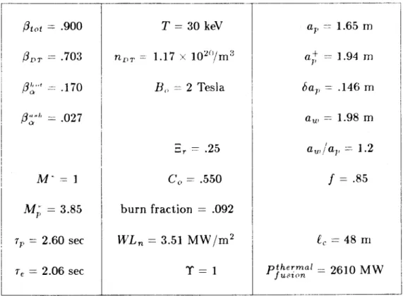
0 1 .900 .703 .170 .027 M- = I Mj, = 3.85 72 = 2.60 sec T, = 2.06 sec T = 30 keV no =1.17 x 10 2"/m 3 B, = 2 Tesla -, = .25 .550 burn fraction = .092 WL, = 3.51 MW/m 2 T =Pt f a1, =1.65 m a+ = 1.94 m 6a, = .146 m a, = 1.98 m 1.2 f .85 -, = 48
rn
uerim' 2610 M Wap
2m
-(m-3)nDT
204.10
20 2.10-i i 120
40
T (kev)
.95 .9 .8 U I"20
40
T
(ev)
60
12
M*
P-
10-
8-
6-
4-
2-60
20
T
40
(keV)
.95 .9 4.820
40
T
(keV)
Parametric scans for the high 3 Mirror Reactor with
the following parameters fixed: f = .85, a /a = 1.2,
B = 2.5 Tesla, E r = .25 .8 .9
.95-60
.95 .9 .8imt
12
E
8
. 4
Figure 1.6b
(m-3)
nDT
204.10
-2.1020
.9 .820
40
T
(keV)
60
.90 S20
40
T
(keV)
.95 .9-3
20
40
T
(kev)
M
4-
3-
21
-60
20
40
T (kev)
Paramtric scans for the high 3 Mirror Reactor with the
following parameters fixed: f = .85, a /ap = 1.2,
B = 2.5 Tesla, r = .33 16
2m-Im-
-9560
-8-E
'4-C
-j
.95 .9 .8-1
Figure 2.60
I I I A(-3)
n
Dr 4.1020 .95 .920
40
T(kev)
.95 .82.10-60
8
6
.9/3
.8
20
40
Tke
4
+
i - - I ---20
40
T
(IeV)
60
2
-20
40
T
(ke
Parametric scans for the high 1 Mirror Reactor with the
following parameters fixed: f = .8, a /ap = 1.3,
w B =2.5 T, =.25
2m
1m4
60
84-6+
,E
3:.j
4+
2-4-.95 .9 .8
3
Figure 3.60
(
m-3)
nDT
204.1020
2.1
02
40
T(kev)
60
M2
P12-10+
8+
6+
4t
K
2-40
T(kev)
60
.95 .920
40
T(kev)
.95l
.9 .820
40
T(kev)
Parametric scans for the high 3 Mirror Reactor with
the following parameters fixed: f = .85, a /a = 1.2,
w B =3.0Tesla, - = .25
ap
2m
1m+
.95 .9 .820
60
201
16-.96 .9
-3
12-+
.j
8-
4-20
Figure 4.60
i
|
! .
a
I
I
I
I
2m-1m
--(m -3)
n DT
1.10-0_
.95 .820
T
(eV)
6-E
i4
C
:-J
40
60
.95 .9 .820
T (ke)
10-.95 .9 .8
20
40
T(keV)
at
6+
40
60
4-2
-1-20
40
T(kev)
Figure 5, Parametric scans for the high
Mirror Reactor with
the following parameters fixed: f = .85, a /ap = 1.2.
wp BO = 2,0 Tesla _ r =- 25