Publisher’s version / Version de l'éditeur:
Proceedings of the Institution of Civil Engineers, Part 1, pp. 720-735, 1954-11
READ THESE TERMS AND CONDITIONS CAREFULLY BEFORE USING THIS WEBSITE.
https://nrc-publications.canada.ca/eng/copyright
Vous avez des questions? Nous pouvons vous aider. Pour communiquer directement avec un auteur, consultez la première page de la revue dans laquelle son article a été publié afin de trouver ses coordonnées. Si vous n’arrivez pas à les repérer, communiquez avec nous à [email protected].
Questions? Contact the NRC Publications Archive team at
[email protected]. If you wish to email the authors directly, please see the first page of the publication for their contact information.
NRC Publications Archive
Archives des publications du CNRC
This publication could be one of several versions: author’s original, accepted manuscript or the publisher’s version. / La version de cette publication peut être l’une des suivantes : la version prépublication de l’auteur, la version acceptée du manuscrit ou la version de l’éditeur.
Access and use of this website and the material on it are subject to the Terms and Conditions set forth at
Strain measurements on the temporary road deck for the Toronto
subway
Schriever, W. R.
https://publications-cnrc.canada.ca/fra/droits
L’accès à ce site Web et l’utilisation de son contenu sont assujettis aux conditions présentées dans le site LISEZ CES CONDITIONS ATTENTIVEMENT AVANT D’UTILISER CE SITE WEB.
NRC Publications Record / Notice d'Archives des publications de CNRC:
https://nrc-publications.canada.ca/eng/view/object/?id=200a9f8d-02b4-4cc0-b90f-9ecd6fe3653c https://publications-cnrc.canada.ca/fra/voir/objet/?id=200a9f8d-02b4-4cc0-b90f-9ecd6fe3653cSCHRIEVER ON STRAIN MEASUREBIENTS ON THE 7 20
TEMPORARY ROAD DECK FOR T H E TORONTO SUBWA
Paper No. 5986
''
Strain Measurements on the Temporary Road Deck for the Toronto Subway "by
William
Robert Schriever(Ordered by the Council to be published with written discussion)
t
SYNOPSIS
Strain measurements were made on the deck beams and some other parts of the temporary steel structures of the street deck used during the construction, by the cut- and-cover method, of the Yonge Street Subway in Toronto, Canada. The results of measurements on the various deck beams are presented.
The investigation included both normal traffic loads a n d heavy load combinations. The maximum values of stresses and the frequency of occurrence of loads are discussed, with a view t o improvement in similar designs which may be used in the future.
IN using a certain allowable stress in the design of a n engineering structure, an engineer usually visualizes the factor of safety as the ratio of the stress at failure to the allowable stress with which he is designing. He may also think of another factor of safety with regard to yield, namely, the ratio of the stress a t the beginning of inelastic yield to the maximum stress occur- ring in the critical points in the design of the structure. He knows that values of about three and two respectively, are used at the present time for these two factors of safety for structural steel. The engineer should consider whether the above values actually represent the factors of safety of the full-scale structure, and further, what this factor should be.
Professor Pugsleyl has reviewed some of the many considerations enter- ing into the question of safety in structural engineering, and has pointed out that the " stress factor of safety " was introduced and connected directly with early material testing which, in a new and unprecedented way, provided numerical values for the strength of various materials. Pre- viously, only " load factor of safety " had been used, that is, the ratio of the load required to break a girder to the greatest load the girder would actually have to carry.
t
Correspondence on this Paper should be received a t the Institution by the 16th March, 1955, and will be published i n Part I of the Froceedings. Contributions should be limited to about 1,200 w o r d s . 4 ~ 0 . I.C.E.A. G. Pugsley, "Concepts of Safety in Structural Engineering." J. Instn Civ. Engrs, vol. 36, p. 6 (March 1961).
721 SCHRIEVER ON STRAIN hXEASUREMENTS ON THE
In the early days, as Pugsley remarks, most maximum external loads acting on bridges and buildings, apart from wind loads, were thought to be clearly dehable and, in most cases, no question of the likelihood of their actual occurrence arose. I n aeronautical engineering, however, ideas of the probability, or frequency of occurrence of loads had to be introduced into considerations of margins of safety. Laboratory tests to destruction of complete wings of an aircraft type which had shown some failures from overloading in service, permitted application of the results of actual loading experience to other cases. Such is not the case for large civil engineering structures where it is usually impossible to depend on tests to destruction and where external loads are frequently difficult t o measure and are, to a certain extent, uncontrollable. Empirically limited working stresses, linked with conventional stress calculations for idealized loading cases, are therefore generally used.
On the other hand, where external loads can be controlled by the designer, a new outlook on margins of safety, and therefore, greater overall structural economy becomes possible. For no structure can the maximum load to which it will ever be subjected be forecast with absolute certainty. There is, therefore, always some "accident risk
"
involved, although the risk may be extremely small. The responsibility as to what extent this possibility of excessive loads, as well as to what extent de- ficiencies of design and workmanship, corrosion, etc., should be allowed for in the design, does not normally fall upon the designing engineer ; building codes or other regulations specify the design load and the greatest allowable stresses with which he may design permanent structures. Such specifica- tions, however, are general rules and must necessarily be rather conserva- tive. Correspondingly, inaccuracies of design assumptions are usually towards the safe side only.There is often a regrettable tendency to regard extreme safety in a structure as a virtue in itself, without due consideration to whether such a degree of safety is actually necessary, or whether the public actually wants to be protected to such an extent. Where heavy load combinations approaching, or reaching, the design load are likely to occur only very rarely or not at all, it does not seem reasonable to consider the design load on the basis of the usual allowable stress (that is, to provide the full factor of safety) especially in cases where the " load factor of safety
"
probably considerably exceeds the"
stress factor of safety." The fact that extreme load combinations, such as the coincidence of an extreme wind with an extreme snow load on buildings, are not very likely has been recognized in practice, and is often allowed for by an increase in permissible working stresses. Another example of the improbability of coincidence of extreme loads is in the design load for tall buildings since it is assumed that it is unlikely that on all floors the maximum floor loading will occur simul- taneously.TEMPORARY ROAD DECK FOR THE TORONTO SUBWAY 722
frequency or probability of occurrence of heavy load combinations. This generally means making a statistical study of continuous records of traffic loads passing over the structure. If continuous records of strains occurring in a main member are taken, these would indirectly represent traffic loads. They can, however, for practical reasons, be considered in terms of stresses, rather than strains, or loads. If the results are plotted, a typical frequency- distribution diagram would generally be obtained. In such a diagram, stresses corresponding to loads of the magnitude of the design load would probably be beyond the values that can be shown by such a curve. Con- sequently, in all practical cases where records cannot be obtained over extremely long periods, the frequency of very heavy loads may only be obtained by extrapolation of the curve. Extrapolating from frequencies of measured loads to the frequencies of extreme loads is difficult, however, and sometimes of doubtful value. When certain d e h i t e loads become predominant, such as the weights of street-cars, and ready-mix concrete trucks, the shape of the frequency-distribution curve varies greatly from the normal curve, which is obtained for instance for rain storm precipita- tion, wind pressures, etc., and statistical rules cannot be applied. The theory of probability, then, is no substitute for the measurements of a great number of actual loads, because no matter how much time is spent on curve fitting, the accuracy of the curve for extreme loads is uncertain. Consequently, sound judgement has to be used without much quantitative help from statistics. The magnitude of the extreme loads, however, can often be fairly accurately known because of the truck size distinctions.
The foregoing considerations were, in part, responsible for the decision of the Division of Building Research of the National Research Council of Canada to undertake a study of the strains actually developed in the steel deck beams of a large temporary structure. This was the temporary roadway which was necessary in the down-town business district of Toronto, capital city of the Province of Ontario, Canada, to permit the construction of a modern underground rapid transit line.
This project, which will cost about sixty million dollars, is being under- taken by the Toronto Transportation Commission, a public body respon- sible for all public transport in the city. The National Research Council's Building Research organization was privileged to use the subway project, during construction, as a large-scale research laboratory. The Author spent two years as research engineer on the project, working co-operatively with the construction staff of the Toronto Transportation Commission. The Commission, in addition to assisting the National Research Council staff mainly through the personnel of its Testing Subsection, also made available the following : -
723 SCHRIEVER ON STRAIN MEASUREMENTS ON THE
(1) Auxiliary equipment, such as the special hut for housing the equipment during the tests.
(2) The use of the soils laboratory, and of some of the workshop services.
(3) The use of the crane car with crew for loading of the deck beams. (4) The use of the automobile assigned to the Testing Subsection.
(5) The co-operation of the traffic inspectors during t h e loading of the deck beams.
The National Research Council supplied personnel and all scientific equipment.
The first line of the proposed Rapid Transit system is the Yonge Street Line, now often referred to simply as the Toronto Subway. Of the total length of 4.6 miles, roughly one-third has been constructed under heavily travelled streets in the heart of t h e city, mainly under Yonge Street and Front Street, by the cut-and-cover method of construction. This method, by which the subway is built from the ground surface, was imperative because the subway was designed to be as shallow as possible to facilitate passenger transfer to and from surface transport, and because of the local geological formation. During construction, all normal traffic including street-cars was carried on a temporary road deck, while the major part of the excavation and the construction of t h e reinforced- concrete subway structure proceeded underneath.
Support of the sides of the cut against earth pressure, and support for the loads on the deck was achieved by steel H-piles, known as soldier piles, which were driven into the ground along both sides of the street, at 6-to- %foot intervals. The first part of the excavation was then carried out, to take care of the great number of utilities, and to install the road deck. Normal street traffic was resumed on the temporary road deck, while construction work continued underneath. Wooden lagging was inserted between the soldier piles as the excavation deepened until it reached final grade, which is about 30 to 40 feet below t h e street surface. The actual subway structure, consisting of a reinforced-concrete " box," was then constructed, sand backfill placed on top, and the street repaved after removal of the deck.
The remaining two-thirds of the subway consisted partly of cut-and- cover sections not under city streets but on a private right of way, a little distance from Ponge Street, and partly of open cut, with cross-streets on overhead bridges.
Various types of road deck construction were used, depending on the required span, the available clearance underground, and the steel sections available a t the time of construction which was a period of steel shortages. For the box sections of the subway (that is, between stations), intermediate sections (transitions, etc.), and some of the narrower stations, 36-inch broad-flange beams of various weights were used ; for station sections
TEMPORARY ROAD DECK FOR THE TORONTO SUBWAY 724
either trusses or 36-inch broad-flange beams with knee braces or posts to reduce the unsupported span. Typical deck constructions of the three main classes are shown in
Pigs
I to 3. Trusses, used extensively in the first station sections a t Queen Street and at Union Station, were not used soPig. I
, 3 6 ' B.F.0 170 Ib. ( u p t o 300 Ib.
F e e t 0 I 2 3 4 5 f e e t
u
much later mainly because, although lighter in weight, they involved for more labour for placing and welding and were not so adaptable for re-use. Attention t o the measurements was therefore concentrated on the beam- type deck construction.
Construction of the road deck proper followed this sequence. First, along each side of the street, soldier piles were driven into the ground.
725 SCHRIEVER O N STRAIN MEASUREMENTS O N THE
Pig. 2
4 0 Ib. B.F.0, uringe
8 ' x 10 Ib. 0.F.B. knee brace
Scale
0 1
-
1 3 4 5 rcctEXAMPLE OF BEAM WITH KNEE BRAOES. EARTH SUB-GRADE
Fig. 3
Scale
Fig. 6
TE~IPORARY Roan DECK COIIPLETID. NOTE I N S T R U ~ I ~ B X T HUT I:OR
TEMPORARY ROAD DECK FOR THE TORONTO SUBWAY 726 The required depth of driving was 8 feet below the final grade level in soil, whilst in rock the piles were driven to refusal. The pavement and the street- car rails were then removed and the first lift of the excavation taken out from the surface by a power shovel. Excavation around the many utilities, however, had to be done by hand. The soldier piles were all cut off at the same depth below street surface and capped by steel beams. By means of two truck-mounted cranes, the main deck beams were then laid across the street a t 12-foot intervals (Pig. 4) supported laterally by timber spreaders and tie-rods, and fastened to the cap beams by welded brackets. Stringer beams were next welded to the web of the main beams and 12-by-12-inch timbers laid along the outer lanes for use by the truck-mounted crane. The utilities were attached to the underside of the deck by steel cables or suitable timber construction (Pig. 5). W t h the l a y i ~ ~ g of ties, street-car rails, and the remaining part of the deck timbers. lrlporary roadway was completed and traffic was resumed (Pig. 6 ) .
STRAIN MEASUREMENTS
rain measurements were carried out OIL deck beams,
lements of the temporary strrlctare for which an improvement in economy of design would obviously be rnost important. Only a few measurements were made on one of the trusses used for the wider span of the station sections of the subway. Because of the much greater amount of labour involved in the cutting, assembling, and welding, trusses were abandoned in favour of broad-flange beams with knee braces. The knee braces not only served to reduce the free span of the wide flange beams, but also acted as partial shoring of the supporting piles against earth pressure. They, therefore, represented structurally one step in the transition from a frame to an arch with a corresponding reduction
-
of bending moment. Appreciable stresses were accordingly expected inthe knee braces themselves, especially in view of the fairly light steel sections used ; a number of strain measurements were consequently made on these braces.
The stringers represented the main longitudinal element in tile deck which could be considered as a grid system for analysis. Consequently, when stresses in the deck beams were found to be low, measurements were also made on some stringers to investigate the distribution of load from one loaded deck beam to its neighbours.
Since all deck beams had constant cross-sections, measurement in the section of the maximum stresses was considered sufficient. Strain gauges, therefore, were attached a t the centre of the span, which in most cases co- incided approximately with the centre-line of the street and of the street- car tracks. I n one case, measurements were also taken at the quarter- points of the span.
727 SCHRIEVER ON STRAIN MEASUREMENTS ON THE
the magnitude and the frequency of traffic load stresses, the two main types of strain measurements made were :-
Recording of strains in deck beams caus (street-car, weighed Toronto Trans crane-car, and weighed ready-mix con rding of strains caused by normal otor traffic) over longer periods of ti The following two special strain tests,
a ) Determination of impact effect
passage of slow and fast movin
(b) Determination of effectiveness of in the main deck beams. and in addition, there were two special in
(c) Determination of the continuity effect in the stringers.
(a)
Observation of the simultaneity of ready-mix concrete trucks) on one be placing operation.nsiderable study, i t mas decided t with two types of gauge, an 8-inch mechanica electrical resistance-wire strain gauges, known as with amplifiers and a direct writing recorder.
EXPERIMENTAL RESULTS
I n order to determine the maximum combination of loads corresponding closely
was used. It was found, however, that owing to traffic on Yonge S it would be too difficult to position the combination of cars used sisting of a crane-car, a street-car of the
mission, and two or more heavy trucks), a
Strains caused by these loads acting separately were, therefore, me and added together, using the law of superposition, except for the car and the street-car the load effects of which were measured taneously. The law of superposition may not be strictly valid for the deck because the continuity effect of the deck timbers may c
a progressively increasing distribution of the load on to t
beams. Should this be the case, however, t h st~esses) produced by the separate loads co strain (or stress) produced by the combined
TEMPORARY ROAD DECK FOR THE TORONTO SUBWAY 728
According to the specifications of the Toronto Transportation Commis- sion, the design load for the temporary street deck consisted of the following loads :-
(1) A train on each street-car track, consisting of two or more 50-ton double-bogie cars, 40 feet long ; each axle load to be 12.5 tons ;
axle spacings t o be 5, 20, and 5 feet.
(2) A column of trucks on each traffic lane of 10-foot width, con- sisting of one 20-ton truck, preceded and followed b y 15-ton trucks ; the load on the rear axle (or axles) to be
$
of the total truck load and the spacing of t h e trucks 44 feet. Considering one deck beam alone in a simplified may, the design load consists of the following double axle loads acting mainly on one beam :-1 truck 1 street-car 1 street-car 1 truck 16 tons 25 tons 25 tons 16 tons
The load used in the experiments, although varying slightly from test to test, was generally as follows :-
1 truck 1 crane-car 1 street-car 1 truck 17 tons 33 tons 174 tons 17 tons
It can be seen that the magnitude of the test load with regard to its effect on bending moments was reasonably similar to the design load.
The strains and resulting stresses measured in the various beams under the above-mentioned loads are given in Table 1 (Plate I ) , in which the following load cases are shown separately : one street-car north-bound ;
one street-car south-bound ; crane-car north-bound ; crane-car north- bound plus street-car south-bound; one concrete truck north-bound ;
one concrete truck south-bound ; the last three loads combined. The maximum stresses obtained range from 5,500 lb. per square inch to 8,500 lb. per square inch. Fig. 8 gives a reproduction of two test records obtained during load tests.
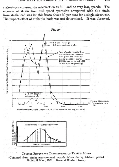
For each beam, investigated strains caused by norlllal traffic on Yonge Street were recorded for various periods of time, to obtain an idea of the frequency of occurrence of various loads. For the beam a t Shuter Street a continuous twenty-four-hour record of strains caused by all traffic was obtained. Fig. 9 shows distribution of strains (grouped by the numbers of lines of chart deflexion) during the twenty-four-hour period. Fig. I 0
gives the same measurements in a different manner; for typical hours of the day the number of occurrences of the various strains is plotted. I n
Fig. 1 6 the characteristic two pairs of strain peaks caused by the bogies of the front car and the trailer car can be seen.
Thc effect of impact is usually greatest a t street intersections, where street-cars passing over the rail crossings cause vibrations of t h e deck. This effect was determined in one case (for a beam at the intersection of Yonge Street and Wellington Street) by comparison of strains caused by
729 SCHRIEVER ON STRAIN MEASUREMENTS ON THE
Pig. 8
Scalc
2 m i n I 0
LOADING TEST WITH WEIGHED T T C CRANE CAR WESTBOUND PLUS STREET CAR SOUTHBOUND (PASSING WHILE CRANE CAR STANDS I N CORRECT POSITION)
LOADING TEST WlTH WEIGHED READY-MIX CONCRETE.LORRY ON TRAFFIC LANES. BOTIi NORTH AND SOUTHBOUND
Pig. 9
Stram rcadtngs: Flbre rrrerr Legend l l n a at centre ofspan
_ _ _
I 190-580 Ib perrq ~n . 2 580-960. . .
3 960-1 350..
.. .
.
4 1,350-1.730.
. ..
5 1 730-2.120. -
---
6 2 120-2,510..
-
, ~9 . 7 2510-2890.
.
-
.
8 2.890-3.280-
8.. .
GRAPH OF ~ ~ E Q U E N C Y OF TRAFFICI LOADS (Eeam at Shuter Street)
TEMPORARY ROAD DECK FOR THE TORONTO SUBWAY 730 a street-car crossing the intersection at full, and a t very low, speeds. The increase of strain from full speed operation compared with the strain from static load was for this beam about 30 per cent for a single street-car. The impact effect of multiple loads was not determined. It was o b s e ~ e d ,
Fig. 10 100 d 3 0 d ", L * Z 2 t, 0 %A w g sa ", d d 3 U 0 5 d m I 3 z STRAIN READING ON IN-ANALISER
CORRESPONDING FIBRE STRESS AT CENTRE OF SPAN LB PER SQUARE INCH
?&'PIC& FREQUENCY DISTRIBUTION OF TRAFFIO LOADS
(Obtained fiom strain measurement records talien during 24-hour period 28 Feb./l Mar., 1951. Beam at Shuter Street.)
however, that the heavier the load combination became the more of its parts were moving slowly or even stationary. Consequently, the impact effect decreased with increasing load.
731 SCHRIEVER ON STRAIN MEASUREMENTS ON THE
Eflectiveness of Knee Braces
Owing to the fact that it was possible to test one station section beam (north of Wellington Street) in three different conditions-with knee braces, with one only, and with none-under normal traffic, a n approxi- mate idea of the effectiveness of knee braces in reducing the centre-span stresses was obtained. I t was not possible, however, to load the beam with the heavy load combination for all three conditions. Table 2 (Plate 2) shows the stresses as determined from the strains measured for the loads of one street-car north-bound and one street-car south-bound for the above mentioned three conditions. The difference between the strains caused by the north- and south-bound street-cars arises because the strain gauges could not be mounted exactly in the centre of the span, owing t o a spieaier beam. The gauge was 10 inches east of the centre of the street as defined by the street-car rails.
The east knee brace was removed first as part of construction opera- tions. The west knee brace was also removed while traffic on Yonge Street was still maintained. It was cut only near its lower end by a n acetylene burner in such a manner as to become effective under heavier loads. The gap created by the burner was just wide enough so that it would not be closed under deflexion from the load of one street-car.
The increase of stress from removal of one knee brace was, on the average, almost 100 per cent ; removal of both knee braces was approxi- mately 200 per cent. If this same increase is applied to the stress from the maximum load combination (6,200 lb. per square inch obtained by superposition) a maximum fibre stress of almost 19,000 lb. per square inch would have been reached.
The stresses in one of the knee braces of the above mentioned beam were also measured. The conclusion that the knee brace would experience the highest stresses near mid-span on the underside was confirmed by taking spot readings a t various points of the lrnee brace by means of the 8-inch mechanical extensometer. Electrical strain gauges were then atta only a t mid-span of the brace and the results shown in Table 2 attained by the gauge on the underside.
The nlaximum stress in the lrnee brace, caused by the usual heav combination totalliilg 84$ tons, was 8,550 lb. per square inch 6,200 lb. per square inch in the deck beam. Both these
obtained by superposition. Consequently, t h e knee brace mas un designed compared to the beam, in fact, considerably more than appears from comparison of the stress values, because of the danger of buckling present in the lrnee brace.
Continuity Effect of the Stringers
The low values of maximum stress obtained in the deck beams led to the conclusion that these beams received considerable load relief, com- pared t o strict simple beam action, by distribution of load to varying
TEMPORARY ROAD DEUK FOR THE TORONTO SUBWAY 732 degrees to the adjacent beams through stringers, rails, and timbers. This load relief was caused by the greater deflexion of the loaded beam, except when all beams were equally loaded (which was never the case with the spacing of beams and loads used on this project). The partial fixity of the ends of the deck beams (welded brackets) also contributed to the load relief, although only to a minor degree.
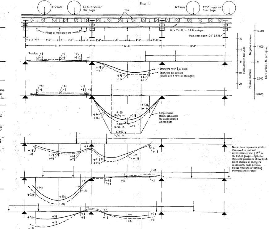
The stringers acted partly as continuous beams through the webs of the deck beams to which they were welded by brackets. The transmission of bending moments through the web of the heavy deck beams was, of course, impeded by the torsional stiffness of the deck beams. As can be seen from the strain lines of Bigs 11, Plate 2, however, some negative moments did act in the non-loaded spans adjacent to the loaded span. The strain readings were taken by means of an 8-inch mechanical extenso- meter on two lines of stringers over two spans, a t the quarter- and mid- span points. The load used consisted of the Toronto Transportation Com- mission crane-car loaded t o approximately 32 tons per bogie, that is, exceeding the specified design load by 7 tons. For the measurements the deck planks covering the ties were removed and the engineer reading the extensometer was standing just below the deck on the partly completed backfill.
The maximum stress recorded in the stringers was 9,400 Ib. per square inch, 25 per cent below the value of 12,600 Ib. per square inch computed for the same steel section acting as a simple beam. The greatest stress measured in an area of negative moment was approximately 1,000 Ib. per square inch.
From the magnitude of strains in the stringers for the load straddliilg
a deck beam, it can be seen that a considerable portion of the load of a truck, or a street-car, or crane-car is always distributed t o the adjacent beam.
Coincidence of Heavy Loads Durir~g Concrete Placing
The likelihood of occurrence of heavy load combinations was greatest during concrete placing operations, when in addition to two street-cars crossing on one beam there might be two ready-mix concrete trucks standing on the side lanes on the same beam. I t is not surprising, however, that during the accurate observation made of one complete placing opera- tion for a roof section, approximately 100 feet south of Dundas Street, during about five hours, not once was a beam loaded simultaneously by two street-cars and two concrete trucks. This becomes understandable when it is considered that only once every two to two and a half hours do two street-cars cross on the same beam, doubling the strain caused by one street- car. This was established from the records obtained by means of the strain analyser equipment.
733 SCHRIEVER ON STRAIN MEASUREMENTS ON THE
during a concrete placing operation the following frequencies of loads were found :-
Two street-cars and two concrete trucks exactly on the same beam : 0 times.
One street-car and two concrete trucks exactly on the same beam : 0 times.
One street-car and two concrete trucks with centre of rear axles at average distance of 1 foot from the beam : 0 times. One street-car and two concrete trucks at average distance of 2
feet : once.
One street-car and two concrete trucks at average distance of 3 feet : twice.
One street-car and 2 concrete trucks at average distance of 4 feet :
8 times.
One street-car and two concrete trucks at average distance of
5 feet : 7 times.
I t follows that even during concrete placing operations, load combina- tions consisting of two street-cars and two concrete trucks acting simul- taneously on the same beam are extremely rare, although definitely possible.
DISCUSSION
OFRESULTS
Lou- Maximum StressesThe two most striking aspects of the results are the low value of stresses obtained under a heavy load combination corresponding closely to the design load and the infrequency of heavy loading by the traffic on the deck. I t is believed that the low stresses in the deck beams principally resulted from the fact that they did not act as simple beams. Two reasons for this were :-
(1) Owing to the load relief from the continuity en'ect of stringers, rails, and deck timbers, the maximum load actually carried by one beam does not correspond to the combined axle loads acting on this beam. "
(2) The welded connexions between the deck beams, the cap beams, and piles introduce a small measure of end fixity into the beams.
The amount of axial load from earth pressure that is transmitted from the soldier piles to the deck beams is limited by the conditions present. The earth pressure acts mainly as a horizontal load on the piles, which are supported at the top by the deck beams, at the bottom by the embedment in the soil and, in some cases, medially by struts. The flexural strength of the steel piles, combined with their unsupported vertical span below the deck beam, limits the reaction in the deck beam and, therefore, the stresses
S T R A I N M E A S U R E M E N T S O N T H E T E M P O R A R Y R O A D DECK F O R THE T O R O N T O
SUBWAY
Subway section. . . .
Location. . .
Chainage. . .
Type. . .
Steel section. . .
Span. . .
Spacing of beams. . . .
Box section At Shuter Street 136+
35 I-beam 36" B.F.B. 182 1b. 34 feet12 feet 37 feet 10 inches South: 6' ; north : 12' 34 feet 12 feet 12 feet
Box section Box section
At Wellington Street
'
At Dundas Square114
+
35 144+
00 I-beam I-beam 36" B.F.B. 230 lb. 36" B.F.B. 182 lb. and 45 lb. 54 feet 12 feet I 4" from top 2" (West) 11" (West) Date of test. . .
Gauge to extreme fibre
. .
Gauge to centre-line of beam Centre-line of road to centre-
line of beam
. . .
4" from top
Station section
North of Wellington Street 115 + 4 4 I-beam knee-braced 36" B.F.B. 182 lb. 4" from top 2" (West) 2" (West) Station section North of Queen Street 132
+
60Truss
Chords : 12" B.B.B., 120 lb.
1 and 2 March, 1951
For all measurements : Type of strain gauge SR-4, A.1. Gauge factor 2.05.
4" from top 10" (East) 5" (West)
Instrument attenuation :-Strain : 1 line on chart = 10p in./in. Stress : 1 line on chart = 300 lb./sq. in. 12 and 18 Jan., 1951
Centre of bottom chord 6' 6" (East)
One street-car (northbound)
(loaded, 174 tons bogie)
.
/
5+/
1,650I
2,100/
3+1
1,050/
1,350I
441
1,350/
1,7501
3/
9001
1,1501
4 1/
1,350/
1,350One street-car (southbound)
17 July and 24 Aug., 1951
Loads on deck beam :
(loaded, 176 tonsjbogie)
:
54 1,650 2,100 3 900 1,050 5 1,500 1,950 2 600 750 3 900 900One crane-car (northbound)
(loaded. 33 tons/bogie)
. .
131
3,9001
5,000 8 11
2,5501
3,300 131
3,9001
5,000lo+
1
3.150 4,0501
121
3,600 3,600Crane car (northbound) 4-
street car; (southb&dj
(loaded 508 tons)
. . .
17+ 5,250 6,750 3,150 4,050 - --
3,600 4,650 - --
Concrete-lorry (northbound)
(on side lane. 17 tons)
.
1
21
6001
7751 1
6751
8501
21
6001
7501 1
9001
1.1501
31
-
1
-
12 Dec., 1950
Stress at :
Strain gauge extreme
(lines) fibre
lb./sq. in.
17 July and 27 Aug., 1951
Stress a t :
Strain gauge extreme
(liues) fibre
Ib./sq. in.
Concrete-lorry (southbound) (on side lane. 17 tons)
.
Maximum load (total of last three : 844 tons by super-position)
. . .
1
2141
6,450/
8,3001
ly
/
4,275/
5,5001
21/
6,600/
8,500/
161
4,800/
6,200/
20/
6,000/
&0001
---
One slow street-car (north-bound) (for minimum im-
pact)
. . .
825 1,050One slow street-car (south- bound (for minimum im-
pact)
. . .
675 850Stress at :
Strain gauge extreme
(lines) fibre
lb./sq. in.
2
WILLIAM CLOWES & SONS* LINITCD : LONDON he Institution of Civil Engineers. Proceedings, Part I, November 1954
300
PLATE I
Stress at :
Strain gauge extreme
(lines) fibre
lb./sq. in.
600
Shuter St and DundJr Square 1'
Streec-car Street-car Lorry
A A-
m
-
m
,
T
-z---~-~-T--== ' 1
Stress a t :
Strain gauge extreme
(lines) fibre lb./sq. in. 400 \ Straln gauge 4 37'-10" Welljngton Sc 775 C o f road (assumed) 2 (assumed)
E L o r r y Street-car I Street-car Lorry w
14
N o r t h o f Wellhngton St
-
W Lorry Street-car Street-car Lorry E
450
-
a .
N o r t h o f Queen Sr
PLATE 2
S T R A I N
R E M E N T S ON T H E T E M P O R A R Y R O A
F O R T H E T O R O N T O
TABLE 2.-STRESSES IN KNEE-BRACED DECK BEAM
Subway section
.
.
.
Location.
. . . .
Chainage. . . .
.
T y p e . .. .
. .
Steel section. . .
.
Span. . . .
. .
Spacing of deck beams
.
Station section
North of Wellington Street 115
+
44I-beam, knee-braced
36" x 182 lb. B.P.B. Knee braces : 8"
x
40 Ib. B.F.B.Total : 57' 2". Between knee braces : 37' 10"
1
12 feetI
Strains and stresses in :FIGS I I
31 7 tons T T C Crane car 32 0 tons T T C crane car
rear bog~e Ttes front bogle
A,
t
10.000 Maan deck beam 36" 0 F 0I
s
One street-car-north
(loaded 174 tons per
bogie)
. . . . .
One street-car-south
(loaded 17* tons per
bogie)
. . .
.
.
One crane-car-north
(loaded 33 tons per
bogie)
. .
.
. .
One crane-car-north
+
one street car (loaded 50* tons)
. . .
.
One concrete-lorry-
north (on side lane,
17 tons)
.
. .
.
One concrete-lorry-
south (on side lane,
17 tons)
. . . .
Max. load of last three, superposition,
%tons
.
. . .
*
See Table 1.t
Increase of stresses compared to beam with both knee braces.The Institution of Civil Engineers.
I
1
,
-
Stringers near c o f deckI
.-+Stringers on o u a ~ d e (There are 4 rows of stringers)
- l a - i t - I I
--
---
A I I I 8 150 S~mple beam stralns (stresses)Note: lincr represent scralns measured In unlts of extensometer d ~ a l ( 10" in. for 8-nnch gauge-length) for lnd~cated posltlons of llve load.
I T Slnce sectlon o f strlngerr
I IS constant. l ~ n e s are alx,
d~rect measure of bending moment and scresses
STRAIN MEASUREMENTS O N STRINGERS ("TRACK BEAMS ") BY MEANS OF A N 8-INCH EXTENSOMETER
TEMPORARY ROAD DEUK FOR THE TORONTO SUBWAY
734
from earth pressure. An estimate for an average deck beam, with struts 10 feet below it, shows an average compressive stress of less than 3,000 lb. per square inch even if the piles were loaded to yield (40,000 lb. per square inch fibre stress). Actually, this force is introduced along the bottom of the deck beam, resulting in a favourable eccentric loading, t h a t is, a tendency to compensate the stresses due to the deck load. In knee-braced deck beams the axial load can become greater because the knee braces, in assuming part of the role of the struts, transfer a greater percentage of the earth pressure t o the deck beam.Infrequency of Heavy Loads
As the records of strains in the deck beams caused by normal traffic show, the other notable aspect of the results is the infrequency of large strains or stresses. It is probable that the majority of the deck beams on the project never normally experienced stresses exceeding three-quarters of the stress obtained under tho heavy experimental load combination used, and were subjected t o this stress only very seldom, that is, only when the crane car was used on Yonge Street. I n the absence of the crane car, the probability of relatively heavy loads acting simultaneously on the same beam was greatest during concrete placing operations. Even then, however, very few beams experienced the full combined load of two street-cars and two full concrete trucks, as the observation of vehicle movements made during a concrete placing operation showed.
Improvement of Econonzy in Puture Designs
One of the principal objectives of this study was to see in what direction improvements might be affected in future designs of the same type of temporary deck structure. The design loads used for this part of the subway were necessarily used in the absence of such specific information as this Paper presents. Nothing in this Paper is to be taken a s any indication of criticism of this quite proper approach to an unusual design problem. Should, however, a similar temporary structure have to be designed in the future, in Toronto or elsewhere, i t does now seem possible for some additional economy to be introduced safely into the proportioning of the deck system.
First, i t seems practicable to make some allowance or reduction in the assumed design load on any one beam, for the continuity which obviously exists even in such a temporary structure a s that which was investigated in Toronto.
To allow for the infrequency of heavy load combinations a further decrease of the design load would seem possible, because the probability of occurrence of the heavy load combinations is small. I n fact, a con- siderable saving might be obtained by regulating the movement of such vehicles as the crane-car, by issuing instructions with regard t o passing other vehicles on any temporary deck. If, in this way, drivers were not
735 SCHRIEVER ON STRAIN MEASUREMENTS ON T H E TEMPORARY ROAD DECK FOR THE TORONTO SUBWAY
allowed to pass a street-car and two heavy trucks at the same time, consideration of a further reduction in the design load would be possible. Even if drivers of specially heavy cars neglected to observe instructions, the factor of safety inherent in the allowable design stress would be ample to take care of the slight temporary overloading.
The investigation of the effectiveness of the knee braces showed the great benefit produced by these braces in reducing the bending moments i11 the deck beams. The knee braces would seem, therefore, to be of great value in saving steel in the deck beams, and possibly also in the box sections of the subwav. when circumstances allow their use. The knee " . braces help to reduce the need for strutting by transferr
percentage of the earth pressure from the piles to the deck b
ACKNOWLEDGEMENTS
Much assistance has been received by the Author during his work. It
would be impossible to list all those who have given a helpful hand in the work itself or in the form of suggestions during discussions. Special mention, however, must be made of the co-operation of the Toronto Transportation Commission and the staff of the Testing Subsection of the Rapid Transit Department in particular, without whose help the work could not have been carried out. The co-operation of the general con- tractor for the down-town section of the subway, Messrs Pitts, Johnson, Drake and Perini, is also acknowledged. Gratitude is expressed for the many helpful suggestions (and the loan of some equipment) from the staff of the Research Laboratories of the Hydro-Electric Power Commission of Ontario.
The Paper is a contribution from the Division of Building Research, National Research Council of Canada. As noted, all the work described was carried out co-operatively with the Toronto Transportation Commis- sion, of which Mr W. H. Paterson is Chief Engineer. Mr D. H. MacDonald, in charge of the Testing Subsection of the Rapid Transit Department worked closely with the Author in this study. The Paper is
the approval of the Commission and of the Director of t h R. F. Legget, M.I.C.E., who followed the work described wi attention.
The Paper is accompanied by four photographs and nine sheets of drawings, from some of which the half-tone page plates, folding