Science Arts & Métiers (SAM)
is an open access repository that collects the work of Arts et Métiers Institute of Technology researchers and makes it freely available over the web where possible.
This is an author-deposited version published in: https://sam.ensam.eu
Handle ID: .http://hdl.handle.net/10985/17424
To cite this version :
Thibault MARSAN, Patricia THOREUX, Maxime BOURGAIN, Olivier ROUILLON, Philippe
ROUCH, Christophe SAURET - Biomechanical analysis of the golf swing: methodological effect of angular velocity component on the identification of the kinematic sequence - Acta of
Bioengineering and Biomechanics - Vol. 21, n°2, p.115-120 - 2019
Any correspondence concerning this service should be sent to the repository Administrator : archiveouverte@ensam.eu
Biomechanical analysis of the golf swing:
methodological effect of angular velocity component
on the identification of the kinematic sequence
THIBAULT MARSAN1*, PATRICIA THOREUX1, 2, MAXIME BOURGAIN1, OLIVIER ROUILLON3, PHILIPPE ROUCH1, CHRISTOPHE SAURET1
1 Arts et Metiers ParisTech, Institut de Biomecanique Humaine Georges Charpak, Paris, France. 2 Hôpital Avicenne, Université Paris, Bobigny, France.
3 Fédération Française de golf, Perret, France.
Purpose: The golf swing is a complex whole-body motion for which a proximal-to-distal transfer of the segmental angular velocities
from the pelvis to the club is believed to be optimal for maximizing the club head linear velocity. However, previous experimental results about such timing (or kinematic sequence) are contradictory. Nevertheless, methods that were used in these studies differed significantly, in particular, those regarding the component of the angular velocity vector selected for the identification of the kinematic sequence. Hence, the aim of this study was to investigate the effect of angular velocity vector component selection on the identified kinematic sequence. Methods: Thirteen golfers participated in this study and performed driver swings in a motion capture laboratory. Seven meth-ods based on different component selection of segmental angular velocities (vector norm, component normal-to-sagittal, frontal, trans-versal and swing planes, segment longitudinal component and a method mixing longitudinal and swing plane components) were tested.
Results: Results showed the critical influence of the component chosen to identify the kinematic sequence with almost as many
kine-matic sequences as the number of tested methods for every golfer. Conclusion: One method seems to show the strongest correlation to performance but none of them can be assessed as a reference method for the identification of the golf swing kinematic sequence. Re-garding the limited time lag between the different peak occurrences and the uncertainty sources of current materials, development of simulation studies would be more suitable to identify the optimal kinematic sequence for the golf swing.
Key words: golf; kinematic sequence; angular velocity; methodology; component selection
1. Introduction
The golf swing is a complex and highly coordi-nated whole-body movement allowing the ball to travel long distances. Some authors already demon-strated the link between the player level, i.e., its handicap, and the club head linear velocity at the ball impact [8]. From a mechanical point of view, the ball flight initial velocity increases with the club head kinetic energy at the ball impact, and by consequence with the club head linear velocity.
In striking or throwing sports, where the athletes aim at maximizing the velocity of an object at the end of a kinetic chain, Putnam [14] showed the interest of body segment sequential motions following a proxi-mal-to-distal sequence, based on a transfer of me-chanical energy between the body segments. She also recommended the expression of this sequence based on the segmental angular velocities because “it leads to an intuitively pleasing way of explaining segment motions”. Several authors applied this concept of kinematic sequence to the golf swing but with contro-versial experimental results. All the studies reported
* Corresponding author: Thibault Marsan, Arts et Metiers ParisTech, Institut de Biomecanique Humaine Georges Charpak, 151 bd de l’hôpital, 75013 Paris, France.
an increase of the maximal angular velocity from the pelvis to the club. However, the timing in which these maxima were reached was debated. Indeed, if some authors [3], [9], [20], [21] reported this theoretically ideal proximal-to-distal kinematic sequence, i.e., from the pelvis to the club; others [7], [13] did not report any specific kinematic sequence. Neal et al. [13] con-cluded that despite a high club head velocity being necessary to make the ball travel long distances, the quality of the contact between the club and the ball at the impact is crucial, potentially affecting the occur-rence of the proximal-to-distal kinematic sequence.
However, the analysis of the methods used in these different studies revealed important differences. These included the acquisition rate of the motion capture systems, the calculation method of the segmental an-gular velocity, and also the component of the anan-gular velocity vector that was selected to identify the kine-matic sequence. Indeed, some authors used the norm of the angular velocity vector [9], [13], [21], others reported the use of only one component of this vector [3], and others did not provide such details [7]. Con-sidering the heterogeneous results from the literature and the various methods that were used, it can be questioned if the methodological aspects could lead to the divergence reported in the previous studies.
To answer this question about the role of the methodological aspects in the identification of the kinematic sequence, this study aimed at investigating the effect of angular velocity component selection on the identification of the kinematic sequence. Gener-ally, the swing motion is assumed to be performed through a planar movement during the downswing [10], [18], [22]. In this theoretical case, the choice of the component would not impact the sequence
identi-fication nor the timing. However, some authors also demonstrate that if a functional swing plane for the club can be defined during the downswing phase, the motions of the different body segments can occur outside this swing plane [4]. In such case, the homo-geneity of the identified kinematic sequence whatever the selected angular velocity component is no more ensured. To evaluate the methodological effect of the angular velocity component selection on the identified kinematic sequence, experiments were performed on 13 subjects with various golf levels, which was ex-pected to provide various kinematic sequences. Two hypotheses were evaluated as follows: (1) the angular velocity component selection have a decisive influ-ence on the identified kinematic sequinflu-ence; and (2) some specific choices result in the expected proximal-to-distal kinematic sequence for the best golfers and not for the golfers with the highest handicap.
2. Material and methods
Participants and data collection
Thirteen right-handed male golfers with various golf levels (from handicap 20 to professional golfers) were involved in this study, which was ethically ap-proved (CPP Ile de France X, France, 2015-A01760-49). Subjects were informed of the protocol and signed a written informed consent form before the beginning of the experiments. On average, subjects characteristics were: age: 31.8 ± 9.6 years old (range: 20–50 y.o.); height: 1.87 ± 0.05 m (range 1.79–1.95 m); and body mass: 91.8 ± 9.4 kg (range 80–105 kg).
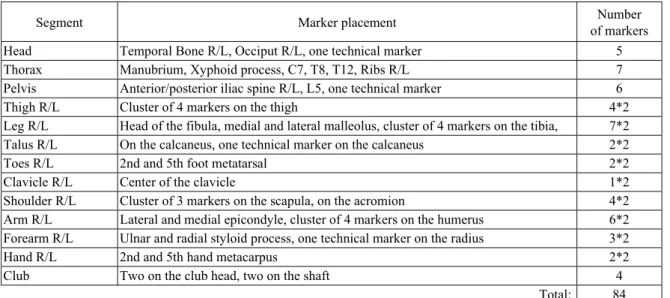
Table 1. Positions of all the markers. R/L means that there were markers on both right and left side of the body.
Segment Marker placement of markersNumber
Head Temporal Bone R/L, Occiput R/L, one technical marker 5 Thorax Manubrium, Xyphoid process, C7, T8, T12, Ribs R/L 7 Pelvis Anterior/posterior iliac spine R/L, L5, one technical marker 6
Thigh R/L Cluster of 4 markers on the thigh 4*2
Leg R/L Head of the fibula, medial and lateral malleolus, cluster of 4 markers on the tibia, 7*2 Talus R/L On the calcaneus, one technical marker on the calcaneus 2*2
Toes R/L 2nd and 5th foot metatarsal 2*2
Clavicle R/L Center of the clavicle 1*2
Shoulder R/L Cluster of 3 markers on the scapula, on the acromion 4*2 Arm R/L Lateral and medial epicondyle, cluster of 4 markers on the humerus 6*2 Forearm R/L Ulnar and radial styloid process, one technical marker on the radius 3*2
Hand R/L 2nd and 5th hand metacarpus 2*2
Club Two on the club head, two on the shaft 4
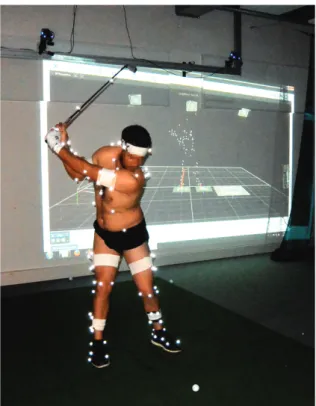
Participants were equipped with 84 reflective mark-ers, including anatomical and technical markmark-ers, al-lowing a full-body analysis (Table 1 and Figs. 1 and 2) and the definition of segment coordinates systems following recommendations from the International Society of Biomechanics [23]–[25]. After completing their own warm-up routine, including practice swings to get comfortable with the environment and the experi-mental setup, participants performed 10 swings with their own driver, shoes and glove. Locations of the re-flective markers were captured using a 12-cameras
Fig. 1. Photograph of the experimental set up with a golfer equipped with reflective markers (here with an iron-6)
Fig. 2. Position of all the markers on the body
optoelectronic motion capture system (Vicon®
Sys-tem, ©Oxford Metrics Inc., UK) working at 200 Hz.
Finally, the best swing of each participant was se-lected for analysis, based on the club head linear ve-locity at impact measured by a dedicated launch monitor (TrackMan 3, Trackman, USA).
Data preparation and data processing
Markers trajectories were smoothed with an aver-age sliding window (5 values) with 2-passes in reverse direction to minimize the shifting effect. This corre-sponds to a low-pass, zero-phase filter with a cut-off frequency of 18 Hz. Gaps in trajectories were filled us-ing a C2-spline interpolation (gaps lower than 15 frames, i.e., 0.075 s) or using a rigid registration based on the other markers of the same segment [17] (gaps higher than 15 frames). The beginning of the downswing was visually identified based on the change of direction of the club head markers. The ball impact was defined as the instant the club head markers reached their ini-tial mediolateral position at the beginning of the take away.
Kinematics were obtained through a multibody kinematic optimization [11] with a full-body model [1] based on previous available models [15], [16]. The data processing was performed in OpenSim 3.3 soft-ware [5] using a classical workflow starting with the scaling of the model to fit the subject anthropometry, followed by a multibody kinematic optimization pro-viding segmental angular velocities in the local coor-dinate systems. The segmental angular velocities were smoothed with a Butterworth filter (5 Hz, zero-phase, with a total order of 4).
Kinematic sequence
Seven methods were investigated to determine the kinematic sequence, all relying on the same segmental angular velocity vectors, and considering the segments: pelvis (P), thorax (T), lead arm (A), lead forearm (F) and lead hand (H). For the first method (M1) the kinematic sequence was determined from the time occurrence of the maximums of the norms. In the second method (M2), only the longitudinal components in the local segment coordinate systems were considered. The third method (M3), relied on the projection of the angular velocity vectors in the swing plane, i.e., following the direction perpendicular to the swing plane. This swing plane was determined as the least square plane passing by all the points that described the trajectories of the markers fixed on the club from the early backswing to the mid-follow-through [2]. The next three methods (M4 to M6) used the projection of the angular velocity vector onto the
three axes of the global coordinate system: anterior-posterior axis corresponding to the frontal plane (M4), vertical axis corresponding to the transversal plane (M5), and medio-lateral axis corresponding to the sagittal plane (M6). A seventh method (M7) was implemented simi-larly to Cheetham et al. [3] by retaining the longitudinal components of the angular velocity vectors for both the pelvis and the thorax, and the projection of the angular velocity vectors perpendicularly to the swing plane for the arm, forearm and hand. A Matlab routine (MATLAB R2014a, The Mathworks, Inc., USA) was used to make the different projections, the identification of the peak velocities, and their time occurrences for the identifica-tion of the kinematic sequence.
3. Results
Club head linear velocities at ball impact ranged from 36 to 52 m/s (mean 45 m/s, SD: 5 m/s), cor-responding to simulated carries ranging from 144 to 259 m (mean: 216 m, SD: 33 m). Maximal resulting segmental angular velocities (i.e., the norms) were 480 ± 82 °/s for the pelvis (range: 280 to 590 °/s), 605 ± 87 °/s for the thorax (range: 470 to 760 °/s), 1310 ± 236 °/s for the lead arm (range: 1000 to 1700 °/s), 1490 ± 203 °/s for the lead forearm (range: 1150 to 1930 °/s), and 1650 ± 211 °/s for the lead hand (range: 1300 to 2100 °/s).
Fig. 3. Example of time courses of the angular velocity for one participant with method M7
An example of the determination of the kinematic sequence is displayed in Fig. 3. Kinematic sequences with respect to different methods are presented for the 13 participants in Table 2. Overall, according to the different methods, 5 to 7 different results were ob-tained per participant. Regarding M1, i.e., based on the norms, the maximal angular velocities of the pel-vis and the thorax were reached before those of the upper limb segments for most of the participants. The proximal-to-distal sequence (i.e., PTAFH, for Pelvis, Thorax, Arm, Forearm, Hand) was found for the best two performers. However, some good performers (participants No. 9 and 10) exhibited a sequence in
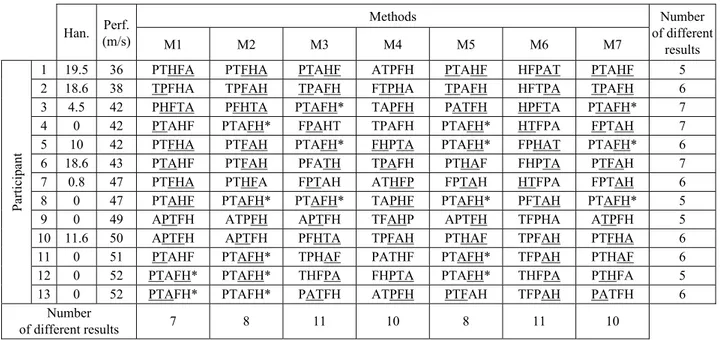
Table 2. Kinematic sequence found for all the participants for all the methods Methods Han. (m/s)Perf. M1 M2 M3 M4 M5 M6 M7 Number of different results
1 19.5 36 PTHFA PTFHA PTAHF ATPFH PTAHF HFPAT PTAHF 5
2 18.6 38 TPFHA TPFAH TPAFH FTPHA TPAFH HFTPA TPAFH 6
3 4.5 42 PHFTA PFHTA PTAFH* TAPFH PATFH HPFTA PTAFH* 7
4 0 42 PTAHF PTAFH* FPAHT TPAFH PTAFH* HTFPA FPTAH 7
5 10 42 PTFHA PTFAH PTAFH* FHPTA PTAFH* FPHAT PTAFH* 6
6 18.6 43 PTAHF PTFAH PFATH TPAFH PTHAF FHPTA PTFAH 7
7 0.8 47 PTFHA PTHFA FPTAH ATHFP FPTAH HTFPA FPTAH 6
8 0 47 PTAHF PTAFH* PTAFH* TAPHF PTAFH* PFTAH PTAFH* 5
9 0 49 APTFH ATPFH APTFH TFAHP APTFH TFPHA ATPFH 5
10 11.6 50 APTFH APTFH PFHTA TPFAH PTHAF TPFAH PTFHA 6
11 0 51 PTAHF PTAFH* TPHAF PATHF PTAFH* TFPAH PTHAF 6
12 0 52 PTAFH* PTAFH* THFPA FHPTA PTAFH* THFPA PTHFA 5
Particip
ant
13 0 52 PTAFH* PTAFH* PATFH ATPFH PTFAH TFPAH PATFH 6
Number
of different results 7 8 11 10 8 11 10
P – Pelvis, T – Thorax, A – Arm, F – Forearm, H – Hand.
*PTAFH is the proximal to distal sequence. The segments underlined have a timing difference under three frames (<0.015 s). Han. is the handicap for all the players, 0 means that the player is a professional.
which the arm angular velocity peaked before the pelvis and the thorax. Method M2, based on segments longitudinal component, provided the highest number of PTAFH sequences (5 subjects), which was found in the best three performers, based on the club head velocity at impact, but also in two others participants (4 and 8) with noticeably lower levels. In the swing plane, i.e., M3, three participants exhibited the PTAFH sequence, but none of them were among the best per-formers. Regarding the projections on the frontal (M4), transversal (M5) and sagittal (M6) planes, none of these methods gave equivalent results. Method M5 provided five participants exhibiting the PTAFH se-quence but with heterogeneous performances (partici-pants No. 4, 5, 8, 11 and 12). Method M6, in the sag-ittal plane, resulted with the hand or the forearm appearing in first or second position for most of the participants. Finally, M7 resulted in 3 participants (participants No. 3, 5 and 8) exhibiting the PTAFH sequence but they were far from being the best per-formers. Finally, for all the methods, the average du-ration between the first and last peak occurrences ranged between 0.13 ± 0.03 s and 0.19 ± 0.04 s and most timing lags between two successive peaks were below three frames (i.e., 0.015 s) (Table 2).
4. Discussion
This study aimed at evaluating the effect of the choice of segmental angular velocity component on the identified kinematic sequence. Thirteen participants were involved with a heterogeneous golf level and performed a golf swing with their personal driver in a motion cap-ture laboratory. The club head linear velocities at ball impact for the best performers were in accordance with results previously reported in the literature on profes-sional golfers (109 mph [3], i.e., about 48 m/s). Maximal angular velocities were also in accordance with previous results [3], [13]. On average, the results of maximal segmental angular velocities were consistent with the principle of angular velocities summation from the proximal to the distal parts of the body [14], as reported in previous studies [3], [7], [9], [13], [20], [21].
Regarding the timing of the segmental angular ve-locities, the results showed the critical influence of the selected components on the identified kinematic se-quence, because the number of obtained sequences was almost as important as the number of tested methods. A proximal-to-distal (PTAFH) sequence was observed in the three best performers when using the longitudinal components in the segment coordinate system (M2), and
for the two best performers when using the norms (M1). This result is in favour of an ideal proximal-to-distal sequence to ensure the highest club head velocity. How-ever, using the longitudinal components, the other two golfers with lower levels also exhibited this ideal se-quence. Because the golf swing is often described as a planar motion for the golf club [10], it could have been expected that the method based on the segmental angular velocities projected in the swing plane (M3) would be the most appropriate to identify the ideal PTAFH se-quence. However, this was not the case in this study. This can be explained by the fact that all the segments do not necessarily rotated in a same plane to result in a pla-nar movement of the club. Indeed, if all the segments rotated in a same plane, M1 and M3–M6 would have given the same kinematic sequence. Other methods also exhibited some subjects identified with a PTAFH se-quence, but these subjects were far from the best per-formers.
Finally, this study demonstrated the crucial influence of the angular velocity component selection on the iden-tification of the kinematic sequence. Although the proxi-mal-to-distal kinematic sequence for the golf swing can still be debated, this study proved that the results from previous studies cannot be used in this debate because of the different methods that were used. In addition, previ-ous studies also varied in term of acquisition rate, seg-ments number and definition, calculation method of segmental angular velocity, etc., whose effects were not investigated in this study. Besides, this study did not investigate the effect of the data preparation such as filtering (type and cut-off frequency) or smoothing (win-dows size, weighting, etc.), or differentiation method, that might also have an important impact on the determi-nation on the kinematic sequence.
Considering the small lag between the first and last angular velocity peak occurrences and the numer-ous sources of inaccuracies with the current systems and methods (such as soft tissue artefacts compensa-tion, etc.), it seems unlikely that the concept of kine-matic sequence can be studied experimentally in a reli-able way. However, if Putnam [14] stated that the kinematic sequence based on the angular velocities was the most intuitive, this can be also be done in terms of segmental contribution to linear velocity of the club head [19] or in term of energy which might be less sensitive to these small lags. In silico study based on multibody simulations, an appropriate solution could be to investigate the golf swing optimal kinematic sequence. This was already done with a simplified model in the swing plane, but our results indicate that the segments do not rotate in the swing plane [12]. Musculoskeletal simulations not restricted to the
swing plane would thus be more suitable. However, this kind of study is complex and needs a full-body musculoskeletal model that can be customizable for each individual. Efforts have been made in this direc-tion [6], but improvements still need to be done at various levels of the model, and, in particular, for the shoulder kinematic chain that was demonstrated to be not suitable [1]. Further works are thus still to be done to perform such in silico studies.
Acknowledgements
Authors would like to thank the French Federation of Golf for their help for recruiting golfers, TrackMan and Titleist for the equipment loan, and the volunteers.
Declaration of interest statement
The authors declare they have no financial or personal rela-tionships with other people or organization that could inappropri-ately influence their work.
References
[1] BOURGAIN M., HYBOIS S., THOREUX P., ROUILLON O., ROUCH P., SAURET C., Effect of shoulder model complexity in upper-body
kinematics analysis of the golf swing, J. Biomech. [Internet].
2018, 75, 154–158, Available from: https://doi.org/10.1016/ j.jbiomech.2018.04.025.
[2] BOURGAIN M., Analyse Biomécanique du swing de golf, ENSAM, 2018.
[3] CHEETHAM P.J., ROSE G.A., HINRICHS R.N., NEAL R.J., MOTTRAM R.E., HURRION P.D. et al. Comparison of Kinematic
Sequence Parameters between Amateur and Professional Golfers, Sci. Golf V., 2008, 30–36.
[4] COLEMAN S.G.S., RANKIN A.J., A three-dimensional
exami-nation of the planar nature of the golf swing, J. Sports Sci.,
2005, 23(3), 227–234.
[5] DELP S.L., ANDERSON F.C., ARNOLD A.S., LOAN P., HABIB A., JOHN C.T. et al., OpenSim: Open-Source Software to Create
and Analyze Dynamic Simulations of Movement, 2007, 54 (11),
1940–1950.
[6] DEMIRCAN E., BESIER T.F., KHATIB O., Muscle force
transmis-sion to operational space accelerations during elite golf swings,
Proc. – IEEE Int. Conf. Robot. Autom., 2012, May, 1464–1969. [7] FERDINANDS R.E.D., KERSTING U.G., MARSHALL R.N., A
twenty--segment kinematics and kinetics model for analysing golf swing mechanics, Sport Technol. [Internet]. 2013, 6 (4),
184–201, Available from: http://www.tandfonline.com/doi/full/ 10.1080/19346182.2013.854799.
[8] FRADKIN A.J., SHERMAN C.A., FINCH C.F., Improving golf
per-formance with a warm up conditioning programme, Br. J. Sport
Med., 2004, 38, 762–765.
[9] HORAN S.A., KAVANAGH J.J., The control of upper body
seg-ment speed and velocity during the golf swing, Sport Biomech.,
2012, 11 (2), 165–174.
[10] KWON Y.-H., COMO C.S., SINGHAL K., LEE S., HAN K.H.,
Assessment of planarity of the golf swing based on the func-tional swing plane of the clubhead and motion planes of the body points, Sport Biomech., 2012, Jun., 11 (2), 127–148.
[11] LU T.W., O’CONNOR J.J., Bone position estimation from skin
marker co-ordinates using global optimisation with joint con-straints, J. Biomech., [Internet]. 1999, Feb 1, [cited 2018, Jul. 18],
32 (2), 129–134. Available from: https://www.sciencedirect.com/ science/ article/pii/S0021929098001584.
[12] MACKENZIE S.J., SPRIGINGS E.J., A three-dimensional
for-ward dynamics model of the golf swing, Sport Eng., 2009, 11
(4), 165–175.
[13] NEAL R., LUMSDEN R., HOLLAND M., MASON B., Body
Seg-ment Sequencing and Timing in Golf, Int. J. Sport Sci. Coach.,
2007, 2, 25–36.
[14] PUTNAM C.A., Sequential Motions of Body Segments in
Striking and Throwing Skills: Descriptions and Explanations,
J. Biomech., 1993, 26, 125–135.
[15] RAABE M.E., CHAUDHARI A.M.W., An investigation of
jog-ging biomechanics using the full-body lumbar spine model: Model development and validation, J. Biomech., [Internet],
2016, 49 (7), 1238–1243. Available from: http://dx.doi.org/ 10.1016/j.jbiomech.2016.02.046.
[16] SETH A., MATIAS R., VELOSO A.P., DELP S.L., A
biomechani-cal model of the scapulothoracic joint to accurately capture scapular kinematics during shoulder movements, PLoS One,
2016, 11 (1), 1–18.
[17] SÖDERKVIST I., WEDIN P.Å.A., SODERKVIST I., WEDIN P.Å.A.,
Determining the movements of the skeleton using well--configured markers, J. Biomech., 1993, Dec., 26 (12),
1473–1477.
[18] SPRIGINGS E.J., NEAL R.J., An insight into the importance of
wrist torque in driving the golfball: a simulation study, Regard
sur l’importance de la force du poignet dans la frappe de la balle de golf: une etude de simulation. J. Appl. Biomech., [Internet], 2000, 16 (4), 356–366, Available from: http://articles.sirc.ca/ search.cfm?id=S-669626%5Cnhttp://proxy.lib.ohio-state.edu/ login?url=http://search.ebscohost.com/login.aspx?direct=true &db=s3h&AN=SPHS-669626&site=ehost-live%5Cnhttp:// www.humankinetics.com/
[19] TEU K.K., KIM W., FUSS F.K., TAN J., The analysis of golf swing
as a kinematic chain using dual Euler angle algorithm,
J. Biomech., 2006, 39 (7), 1227–1238.
[20] TINMARK F., HELLSTRÖM J., HALVORSEN K., THORSTENSSON A.,
Elite golfers’ kinematic sequence in full-swing and partial-swing shots, Sport Biomech., [Internet], 2010, 9 (4), 236–244,
Available from: http://www.tandfonline.com/doi/abs/10.1080/ 14763141.2010.535842.
[21] VENA A., BUDNEY D., FOREST T., CAREY J.P., Three-dimen
sional kinematic analysis of the golf swing using instantaneous-screw axis theory, part 1: Methodology and verification, Sport
Eng., 2011, 13 (3), 105–123.
[22] WHITE R., On the efficiency of the golf swing, Am. J. Phys., [Internet], 2006, 74 (12), 1088–1094, Available from: http:// aapt.scitation.org/doi/10.1119/1.2346688.
[23] WU G., CAVANAGH P.R., ISB Recommendations in the
Re-porting for Standardization of Kinematic Data, J. Biomech.,
1995, 28 (10), 1257–1261.
[24] WU G., VAN DER HELM F.C.T., VEEGER H.E.J., MAKHSOUS M., VAN ROY P., ANGLIN C. et al., ISB recommendation on
defi-nitions of joint coordinate systems of various joints for the reporting of human joint motion – Part II: Shoulder, elbow, wrist and hand, J. Biomech., 2005, 38 (5), 981–992.
[25] WU G., SIEGLER S., ALLARD P., KIRTLEY C., LEARDINI A., ROSENBAUM D. et al., ISB recommendation on definitions of
joint coordinate system of various joints for the reporting of hu-man joint motion – part I: ankle, hip, and spine, J. Biomech.,
[Internet], 2002, 35(4), 543–8. Available from: http:// linkinghub.elsevier.com/retrieve/pii/S0021929001002226.