HAL Id: hal-00344877
https://hal.archives-ouvertes.fr/hal-00344877
Submitted on 9 Nov 2011
HAL is a multi-disciplinary open access
archive for the deposit and dissemination of
sci-entific research documents, whether they are
pub-lished or not. The documents may come from
teaching and research institutions in France or
abroad, or from public or private research centers.
L’archive ouverte pluridisciplinaire HAL, est
destinée au dépôt et à la diffusion de documents
scientifiques de niveau recherche, publiés ou non,
émanant des établissements d’enseignement et de
recherche français ou étrangers, des laboratoires
publics ou privés.
On the hybrid aid-localization for outdoor augmented
reality applications
Imane Zendjebil, Fakhr-Eddine Ababsa, Jean-Yves Didier, Malik Mallem
To cite this version:
Imane Zendjebil, Fakhr-Eddine Ababsa, Jean-Yves Didier, Malik Mallem.
On the hybrid
aid-localization for outdoor augmented reality applications. VRST ’08: Proceedings of the 2008 ACM
symposium on Virtual reality software and technology, Oct 2008, Bordeaux, France. pp.249–250,
�10.1145/1450579.1450637�. �hal-00344877�
On the Hybrid Aid-Localization for Outdoor Augmented Reality
Applications
I.M. Zendjebil∗ F. Ababsa† J-Y. Didier‡ M. Mallem§
IBISC Laboratory, University of Evry Val d’Essonne, CNRS FRE 3190
Abstract
In mobile outdoor augmented reality applications, accurate local-ization is critical to register virtual augmentations over a real scene. Vision-based approaches provide accurate localization estimates but are still too sensitive to outdoor conditions (brightness changes, occlusions, etc.). This drawback can be overcome by adding other types of sensors. In this work, we combine a GPS and an iner-tial sensor with a camera to provide accurate localization. We will present the calibration process and we will discuss how to quantify the 3D localization accuracy. Experimental results on real data are presented.
CR Categories: K.6.1 [Infomation Systems]: Outdoor Aug-mented Reality—; K.7.m [Computer Vision]: 3D localization— Hybrid sensor Calibration
Keywords: Outdoor augmented reality, 3D localization, hybrid sensor, calibration, error prediction
1 Introduction
Vision-based methods are widely used in augmented reality (AR) applications to obtain an accurate registration. In outdoor scenes, these types of methods lack of robustness and accuracy mainly due to outdoor conditions. Adding other types of sensors improves vision-based approaches. Indeed, we can combine GPS to initial-ize visual tracking [Reitmayr and Drummond 2007], fuse inertial sensor data with a visual tracking [Bleser and Stricker 2008] to im-prove stability and robustness, or assist visual tracking with inertial sensor [Aron et al. 2007].
In our work, we combine a GPS with an inertial sensor to assist a vi-sual tracking process. The combination of GPS and inertial sensor represent our Aid-localization system. This combination is used to estimate continuously the user’s position and orientation even when vision tracking fails. The accuracy of this hybrid sensor depends on the accuracy of the calibration procedure that determines the rela-tionship between the different used references frames. We propose two calibration processes to estimate the relationship between iner-tial sensor and camera and the transformation which maps the GPS position to the camera position. The measures provided by the
Aid-∗e-mail:[email protected]
†[email protected] ‡[email protected] §[email protected]
localization module are less accurate. So, we need to quantify these errors in order to correct the estimated position and orientation.
2 Calibration Procedure
Each sensor provides data in its own reference frame. The inertial sensor computes the orientation between a local inertial reference frame RI attached to itself and a global inertial reference frame RG. The GPS’s position is expressed in a global reference frame.
For registration, we need to estimate continually the camera’s pose which relates the world reference frame RW and the camera
refer-ence frame RC. Thus, the pose provided by the Aid-localization
system must be aligned with the camera reference frame RC.
2.1 Inertial/Camera Calibration
We need to estimate the rotation between reference frames attached to the camera and the inertial sensor in order to transpose the ori-entation obtained from one sensor into the reference frame of the other. We define RCW, obtained from the camera pose estimation,
the rotation of the world reference frame RW with respect to the
camera reference frame RC. The rotation of the local inertial
refer-ence frame RIwith respect to RCis RCI. Also, RIGis the rotation
between RI and the global inertial reference frame RGprovided
by inertial sensor. The rotation between the RWand RGis defined
by RGW. Thus, the transformation between the camera and inertial
sensor is defined by RCIand RGWand expressed as:
RCW= RCIRIGRGW (1)
In our case, the Inertial/Camera calibration process consists in esti-mating a rotation matrix RCIand deducing the second rotation
ma-trix RGW. We assume that the Z axis of the global inertial reference
frame RGis pointing up along vertical. To simplify the equation
(1), we define the Z axis of the world reference frame collinear with it (Z axis is along vertical and pointing up). Therefore, RGWis only
a rotation around the Z axis with an angleθ . With this configura-tion, we estimate RCIusing least mean squares from the following
equation:
rCW3 = RCIrIG3 (2)
With rCW
3 and r3IGare the third column of RCWand RIGrespectively.
Then, RGWis deduced using (1):
RGW= RTIGRTCIRCW (3)
2.2 GPS/Camera Calibration
The GPS/Vision calibration estimates the rigid transformation (ro-tation + translation) which allows to deduce the camera’s position from the position provided by the GPS. For each GPS position pgps,
we associate a camera’s position pcamobtained from the estimated
pose (pcam= −RTCWtCW). The relationship between the two
posi-tions is given by: pcam= Rpgps+ t. The rigid transformation is
obtained by minimizing the following criterion:
n
∑
i
We introduce then the vectors−→Nigps= pgpsj − pigps and − →
Nicam =
pcamj − picam with i = 1..n2 and j = n2+ 1..n.. The relationship
de-duced from (4) between them is:
n 2
∑
i
k−→Nicam− R−→Nigpsk2 (5) From equation (5), we can estimate the rotation R. The translation is then deduced from the following equation (With pcam= 1n∑nipicam
and pgps=1n∑nipi gps):
t = pcam− Rpgps (6)
We use GPS to obtain a 2D localization (longitude and latitude). Concerning the altitude, we fixed it according to where we are in the environment.
3 Error Prediction
The error estimation is important in the localization process. In-deed, it allows quantifying the quality of measurements and im-proving the estimate provided by the aid-localization module. Our error represents the difference with respect to the camera’s pose provided by vision method. When the vision fails, we need to pre-dict this error. So, we opt for a regression with a Gaussian process [Williams 1997]. A Gaussian process is a stochastic process which generates samples and can be used as a prior probability distribu-tion over funcdistribu-tions in Bayesian inference. During visual tracking, we record the offset between the hybrid sensor and camera pose. When the visual tracking fails, the Gaussian process allows predict-ing the offset made by hybrid sensor and improves the localization estimate.
4 Experiments and Results
We use data acquired in an outdoor environment to calibrate the dif-ferent sensors and validate the 3D localization using GPS and iner-tial sensor. The camera’s pose used to calibrate the hybrid sensor is estimated using a manual 2D/3D points matching (for accurate estimate). The camera poses are estimated along the images se-quence using a point-based visual tracking and was used as ground truth. To validate Inertial/Camera Calibration, different views were taken with various rotation angles. For each view, we estimated the camera’s rotation using inertial orientation and vision method. The means errors obtained between the two estimated rotations are shown in table 1. The use of inertial sensor allows us to cover the camera’s orientation with low errors. This represents a good result for registration. Concerning position, the transformation between
φ θ ψ
Mean error −0.3460◦ −0.7211◦ −2.293◦
Table 1: Angular means errors in degree
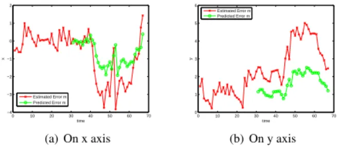
the GPS and the camera was estimated using a set of fixed images (20 images) with geo-referenced coordinates provided by the GPS. The different positions are well spread over the work area. There-after, we tested the validity of the calibration procedure on a set of data taken continuously. Figure 1 and table 2 show the errors ob-tained on meters (red line). The obob-tained results are satisfactory for the purposes of the application (i.e. to assist visual tracking). The GPS position can move closer to the real position using the pre-dicted errors. In our experimentation, prepre-dicted error is estimated with a set of N = 40 last sample (empirically determined). We can see the predicted errors in figure 1 (green line) and table 2.
0 10 20 30 40 50 60 70 −4 −3 −2 −1 0 1 2 x time Estimated Error m Predicted Error m (a) On x axis 0 10 20 30 40 50 60 70 0 1 2 3 4 5 6 y time Estimated Error m Predicted Error m (b) On y axis
Figure 1: Estimated Error vs. Predicted Error Errors µx σx2 µy σy2
Estimated 0.7572m 1.7087m2 2.344m 1.8473m2 Predicted 0.8604m 0.4588m2 0.9015m 0.3174m2
Table 2: Mean errors and variation in meters
5 Conclusion
In this work, we present our hybrid sensor composed of a camera coupled with a GPS and an inertial sensor. The use of the GPS and the inertial sensor provide an estimate of the camera’s pose when visual tracking fails. For this, we propose two calibration processes allowing to deduce the camera’s pose from data provided by these two other sensors. Our calibration processes are distinguished by its simplicity and efficiency. In addition, our methods do not re-quire heavy assumptions. Also, to characterize the quality of the localization of the system, the use of Gaussian process allows pre-dicting the obtained error and thence improving the estimate. The results obtained are quite satisfactory.
Acknowledgements
This work is supported by the RAXENV project funded by the French National Research Agency ”ANR”.
References
ARON, M., SIMON, G.,ANDBERGER, M. 2007. Use of inertial sensors to support video tracking: Research articles. Comput.
Animat. Virtual Worlds 18, 1, 57–68.
BLESER, G., AND STRICKER, D. 2008. Advanced tracking
through efficient image processing and visual-inertial sensor fu-sion. In VR, 137–144.
REITMAYR, G., AND DRUMMOND, T. 2007. Initialisation for
visual tracking in urban environments. In IEEE ISMAR.
WILLIAMS, C. 1997. Prediction with gaussian processes: From
linear regression to linear prediction and beyond. Tech. rep., Neural Computing Research Group, Oct.