Publisher’s version / Version de l'éditeur:
Vous avez des questions? Nous pouvons vous aider. Pour communiquer directement avec un auteur, consultez la
première page de la revue dans laquelle son article a été publié afin de trouver ses coordonnées. Si vous n’arrivez pas à les repérer, communiquez avec nous à PublicationsArchive-ArchivesPublications@nrc-cnrc.gc.ca.
Questions? Contact the NRC Publications Archive team at
PublicationsArchive-ArchivesPublications@nrc-cnrc.gc.ca. If you wish to email the authors directly, please see the first page of the publication for their contact information.
https://publications-cnrc.canada.ca/fra/droits
L’accès à ce site Web et l’utilisation de son contenu sont assujettis aux conditions présentées dans le site LISEZ CES CONDITIONS ATTENTIVEMENT AVANT D’UTILISER CE SITE WEB.
Report (National Research Council of Canada. Division of Building Research), 1952-09-01
READ THESE TERMS AND CONDITIONS CAREFULLY BEFORE USING THIS WEBSITE. https://nrc-publications.canada.ca/eng/copyright
NRC Publications Archive Record / Notice des Archives des publications du CNRC :
https://nrc-publications.canada.ca/eng/view/object/?id=546d5177-d1db-4694-81da-64174e7120c4 https://publications-cnrc.canada.ca/fra/voir/objet/?id=546d5177-d1db-4694-81da-64174e7120c4
NRC Publications Archive
Archives des publications du CNRC
For the publisher’s version, please access the DOI link below./ Pour consulter la version de l’éditeur, utilisez le lien DOI ci-dessous.
https://doi.org/10.4224/20386636
Access and use of this website and the material on it are subject to the Terms and Conditions set forth at
Strain Measurements on the Temporary Road Deck for the Toronto Subway
NATIONAL RESEARCH COUNCIL CANADA
STRAIN MEASUREMENTS ON THE TEMPORARY ROAD DECK FOR THE TORONTO SUBWAY
by
W. R. Schrie ver
ANAL VZED
Prepared in co-operation with the Toronto Transportation Commission
and now circulated for comment
Not for Publication
Research Report Noo
9
of the
Division of Building Research
Ottawa September, 1952
PREFACE
The Toronto Transportation Commission is constructing Canada's first subway. This great construction project cuts
through the heart of downtown Toronto. It is thus beyond
question one of the most complex building operations yet to be carried out in the Dominion. Completion is anticipated by the end of
1953.
The Division of Building r・ウ・。イ」ィセ nセrNcNセ has been privileged to be closely associated with this unusual project
since the start of its キッイォセ following the writer's personal connection as a consultant to the T.T.C. on soil and foundation problems until he came to Ottawa in
1947
to assume his present position. When construction of the subway started (in1949)
the Commission kindly agreed that the dゥカゥウゥッョセ in effect,
might use the job as a large scale "building research laboratory" in return for such special a$sistance as it might render with unusual problems encountered as construction proceeded.
Accordingly, the author of this Report (Mr. W.R. s」ィイゥ・カ・イセ an Assistant Research Officer in the Soil Mechanics Section of D.B.R.) moved to Toronto in s・ーエ・ュ「・イセ QYTYセ and was engaged for the next two years as Research Engineer on the
subway project. He continued to be a member of the D.B.R. staff but acted generally as though he were on the T.T.C. construction engineering staff. The arrangement worked admirably» it is believed to mutual benefit.
Many problems were investigated and some major projects undertaken. This is the first of a number of reports which
will record the results of these invest4.gations. This paper deals with a study of the actual loads to which the temporary road deck structure was subjected and the corresponding actual stresses set up in the steel. It is thus a contribution to the rather limited literature dealing with the true loading of civil engineering structures, a field of work in which the Division hopes to make further studies. The need for research work of this kind has only recently received renewed attention
aS9 for example» in a notable paper by Prof. A. G. Pugsley*.
The practical implications of its conclusions will be obvious. The paper is issued first in this form by agreement with the Toronto Transportation Commission. It is hoped that the
author may be favoured with critical comments from those who
*
Pug s ley , A.Goo "Concepts of Safety in Structural Engineering" Journal of the Institution of Civil Engineers, London,March
1951.
read the paper in this ヲッイュセ If it seems to be agreed by those competent to judge that the paper should be published, the permission of the Commission will be sought for submitting a revised version of this paper to one of the major civil
engineering societies for publication and public discussionv Ottawa
September,
1952.
(11)
Robert F. Legget, Director.
TABLE OF CONTENTS
Page Noo Synopsis
The Toronto Subway
(a) A General Note
(b) Description of the Temporary Road Deck (c) Construction of the Temporary Road Deck The Safety of the Temporary Road Deck
(a) The Safety of Engineering Structures in General
(b) Statistical Approach to the Design Load Problems (c) Fatigue ( iv) 2 3 3
4
6 7 Strain Measurements on the Temporary Road Deck(a) General Remarks 7
(b) Objects and Methods of Measurements
9
(c) Experimental Results 10
ao Strains in Deck Beams Caused by
Known Loads 10
bo Strains Caused by Normal Traffic 11
co Effect of Impact 11
do Effectiveness of Knee Braces 12
eo Continuity Effect of the Stringers 13
fo Coincidence of Heavy Loads During
Concrete Placing 13
g. Strains Caused by Earth Pressure
14
Discussion of Results
(a) Low Maximum Stresses
15
(b) Infrequency of Heavy Loads 16
(c) Improvement of Economy in Future Designs 16
Acknowledgements
Appendix A: Equipment Used for Strain Measurements
(iii)
SYNOPSIS
This report deals with strain measurements made on the deck beams and some other parts of the temporary
steel structures oftre street deck used during the construction of the Yonge St. Subway by the cut-and-cover method. The results of measurements on the various deck beams are presented. The
investigation included both normal traffic loads as heavy load
」ッュ「ゥョ。エゥッョウセ and to some extent, earth pressure. The maximum
values of stresses and the frequency of occurrence of loads are discussed, with a view to improving future design basis.
STRAIN MEASUREMENTS ON THE TEMPORARY ROAD DECK FOR THE TORONTO SUBWAY
by
Wo
a,
SchrieverCanada's first subway has been under construction in Toronto since
1948.
This project, undertaken by the Toronto Transportation Commission, provided good opportuni-ties for study of soil and foundation conditions and of some related design and construction problems. A number of investi-gations were ·therefore unde rt ake n jointly between the Division of Building Research of the National Research Council and the Toronto Transportation Commission.Many problems encountered in the course of the design and construction of a aubway セエイオ」エオイ・ still leave much room for improvement in their solutioQ. Re$earch on some of these questions could therefore contribute to more economical
construction. It i8 hoped that this re,earch may be of interest and value to the construction inqqstry.
Numerous subjeots worthy of investigation were encoun-tered during the design stages of the project and demands for research projects were plentifulo By the time construction began, the number- of pro jec1is· had been reduoed to the following: 10 Recording of a complete engineering and geological soil
profile along the excavation including groundwater observations;
20 The measurement of strains occurring in various steel and timber elements 9f t:pe shoring of the subway exca-vation and of tpe temporarY road deck in order to
determine horizontal and vertical loads;
30
The measurement of ウエイセウウ・ウ occurring in some parts of the permanent reinforced concrete structure;40 The dissipation of ground vibrations due to construction ope rat'-:ons;
50
The recording of soil temperatures beneath the subway; and 60 Observation and stUdy of some construction problems suchas compaction ュ・エィッ、ウセ drainage, and underpinningo Due to the limited staff available both from the Toronto Transportation Commission and the National Research Council, it was necessary to concentrate efforts on one or two of the investigations mentioned above, as all of them required extensive preparations and a great number of routine measurements over many months.
- 2 セ
tィゥセ report deals with the measurement of strains occurring in various steel elements of the temporary road decko This deck is an important part of the construction me thod
known as B」オセ。ョ、M」アv・イBセ which is 、セウ」イゥ「・、 in more detail in the next sectiono Tpe temporary road 、・」ォセ which carries all traffic including セエイ・・エ cars during oonstruction of the subway structure underneath9 represents a major item of cost 9
a very large a.mount of steel being required for it.
The deck members were designed to carry a very heavy combination of loads 」ッョセゥウエャョァ of crane cars9 street-cars and
trucks. In view of this assumed load concentration and the question of the probability of the actual simultaneous occur-rence of such heavy load$9 it was thought that an experimental study of actual ウエイ。ゥョセ in the steel decking would be justified. Although the part of the problem dealing with static loading
(earth pressure and dead load) was also studied 9 the major part of the study was concentrated on the transient stresses
resulting from live loads considered from their two separate aspects: HセI magnitude9 a,nd (b) frequency of occurrence.
z
THE TORONTO SUBWAY(a) A General Note
The ヲャイセエ line of the proposed Rapid Transit System
for Toront09 which is under construction at the present time,
is the Yonge Street Line 9 now often referred to simply as the Toronto Subway. Of the total length of
4.6
miles9 roughlyone third is being constructed under heavily travelled streets in the heart of the city9 mainly under Yonge and Front Stree tsセ
by the 」オセ、M」ッカ・イ method of construction. This construction
method9 by which the subway is built from the ground surfaceD
was imperative9 because the subway was designed to be as
shallow as possible in order to facilitate the passenger transfer to and from surface transportation and because of the local
geological formation. During construction all normal traffic, including st.r-e e t.c c ar-s , is carried on a temporary road de ck , while the major part of the excavation and the construction of the reinforced concrete subway structure proceeds underneath.
Support of the sides of the cut against earth
pressure and support for the loads on the deck is achieved by steel H piles known as soldier piles9 which are driven into
the ground along both sides of the street9 at
6
to8
footintervals. The first part of the excavation is then carried out9 to take care of the great number of utilities and to
install the road deck. Normal street traffic can be resumed on the road deck9 while construction work continues underneath.
Wooden lagging is inserted between the soldier piles as the excavation is deepened until it reaches final grade, which is some 30 to 40 feet below the street surface. The actual subway structure consisting of a reinforced concrete "box" is then constructedD sand backfill placed on top $nd the street repaved after removal of the de ckc
- 3
セThe remaining two third$ of the subway consist partly of 」セエM。ョ、Mセッカ・イ sections not under city streets but on a private right ッセ セ。yァ some distance off Yonge Street g and partly of ッーセセ Cqt, with cross streets carried on overhead
br-Ldge s ,
(b) Description of tbeTemporary Road Deck
v。イゥアTセ types of road deck constructions are used on
this project, depending on the required span» the available clearance underground and also on the steel sections available at the time g which was a period of steel shortageso For the box sections of the subway (ioeo between itations) intermediate sections Hエイ。ョウゥエゥッョウセ etco) and some of the narrower stations, 36-inch wide flange beams of various weights are used; for
station sections either trusses or 36=inch beams with knee braces or posts as a means of reducing the unsupported spano Typical deck constructions of the three main classes are shown in Figso 1 and 20 Trusse,p used extensively in the first
station sections at Queen Street and at Union Station g were not used as mucn later on maiqly because g although lighter in weight» they involve much more labour for placing and welding
and are not as adaptable ゥセ re=useo Attention in the measurements was therefore concentrated on the beam type deck cons tz-uct tona ,
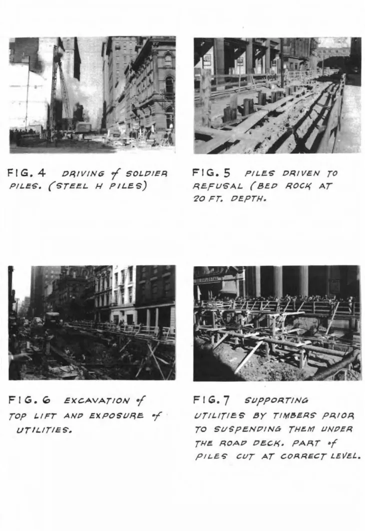
(0) Construction of the Temporary Road Deck
A brief 、・セ」イゥーエゥッョ of the construction work in the "cut-eend-oover-" me tihod haa already been given in a previous chaptero Construction of the road deck proper follows these Li.nee , First» a'l ong each side of the street, soldier piles are driven into the ground (Figo 4)0 The required depth of
driving ia.
8
fto below the final grade level in soil while in rock the piles are driven to refusal (Figo 5)0 The pavement and the street-car rails are then removed and the first lift of the exeavation can be taken out from the surface by a power shovel -(Flgo6)0
Excavation around the many utilities, however, has to be qone by hand (Figo7)0
The soldier piles are allcutoff at tl:1e same depth below street surface and capped by steel be ame, By means of two truck mounted crane" the main deekbeams can then be laid across the street at 12-foot
intervals (Figo
8)
supported laterally by timber spreaders and tie rods and fastened to the cap beams by welded br-acket a , Stringer beams are セ・クエ welded to the web of the main beams (Figo9)
and 12- by 12-inch timbers laid along the outer lanes for use by the truck mounted craneo The utilities are attached to the underside of the deck by steel cables or suitabletimber 」ッョウエイセ」エゥッョ (Figq 10)0 With the laying of ties,
street-car rails and the remaining part of the deck timbers the
temporary roadway is completed and traffic can be resumed (Figo 11)0 The live load assumption which was made in the design
of the deck construction and which was approved by the City of Toronto is show.n graphically in Section
40
All deck beams were designed as simple be ams,=
4
=30 THE SAFETY OF THE TEMPORARY ROAD DECK (a) The Safety of Engineering Structures
in General
In using a certain allowable stress in the design of an engineering ウエイオ」エオイ・セ the engineer usually visualizes the "factor of safety" as the ratio of the stress at failure (strength) to the allowable stress with which be is designing. Possibly he thinks of another factor of safety with regard to yield p ioe0 9 the ratio of the stress at the beginning of
inelastic yield to the maximum stress occurring in the 」イゥエセ」。ャ
points in the design of the structureo He knows that values of slightly over three and two respectivelyp are used at the
present time for these two factors of safety for structural steelo The engineer should always consider also the question whether the above values actually represent the factors of
safety oi: the full=scale structure and, f'ur-tiher-, what this factor should be.
In the light of the many considerations entering into the picture of safety in structural engineering, it seems appropriate to review some of its pertinent aspectso As
Ao Go Pugsley points out in his paper "Concepts of Safety in Structural Engineering" (1) the factor of safety was defined firstp in the late eighteenth century when cast=iron began to
be used as a structural materialp as the ratio of the load
required to break a girder to the greatest load the girder was actually required to carryo It can be seen that this factor of safety does not conform with the term in its present useg
because nowp as mentioned beforep it is generally applied to
stresses and not to loads o A large margin of safety was desirable at that time for cast=iron construction because of the many hidden faults in large castingso Thus a factor of safety of four9 and six in the case of rolling loads to allow
for Lmpact , was used , Latar-, when the beam theory became generally knownp it was possible to use the factor of safety;>
not with breaking and キッイォゥセ loads p but with breaking and working stresses. Thus the stress factor of safety" was
introduced and connected directly with material testing whichp in a new and unprecedented wayp provided numerical values for the strength of various materials.
(1) Journal of the Institution of Civil Engineers» lッョ、ッョセ March;> 1951.
5
-This development paralleled the arrival of wrought iron and mild steel which through their ductility revealed the importance of yield stresses. The ductility in the material introduced the possibility of large inelastic or permanent deformations without actual collapse. This greatly increased the safety of a structure as a whole» that is as long as no buckling was involved, for the stability of columns is, of
」ッオイウ・セ a different matter. It is interesting to note in this
connection that the stress factor of safety became so firmly embedded in engineering practice that even results of column te sts and theorie s were and often still are discussed in terms of stresses rather than loads.
In the early days, as A. Go Pugsley remarks» most of the maximum external loads acting on bridges and buildings» apart from wind loads, were thought to be cle arly definable and in most cases no question of the likelihood of their actual occurrence arose. In aeronautical engineering however, ideas of the probability or of frequency of occurrence of loads had to be introduced into considerations of margins of safety. A military aircraft, for instancep is designed with values of the forces acting on the wings which were based on past experience. If found satisfactory under reasonable conditions, an aircraft would be loaded further with fuel and armament or, be made more manoeuvrable» until some structural failures began to occur. Laboratory tests to destruction of complete wings then permitted
the application of the re su.l ts of this experience to other cases. Such is not the case for large civil engineering
structures where it is usually impossible to depend on tests to destruction and where external loads are frequently difficult
to measure and are to a certain extent uncontrollable. Empirical= ly limited working stresses, linked with conventional stress
calculations for idealized loading cases, are therefore used in general. On the other hand, where external loads can be controlled by the designer» a new outlook on margins of safety and therefore greater overall structural economy becomes possible. As will be
seen later on, in Toronto the maximum load for the temporary road deck could be controlle d to a certain degree.
For no structure can the maximum load to which it will ever be subjected be forecast with absolute certainty. There is therefore always some "accident risk" involved, although this'
risk may be extremely small. In other words, it woUld be uneconomi-cal, even impossible, to design and build a structure that is
absolutely safe, as under unforeseen circumstances, as in an
emergency, it is possible that a heavier load than the design load may have to be carried by the structure. The responsibility as to what extent this possibility of excessive loads, as well as to what extent deficiencies of design and workmanship, corrosion, etc., should be allowed for in the design, normally does not fall upon the designing engineer, for building codes or other regulations specify the design load and the greatest allowable stresses with which he may design permanent structures. Such specifications,
= 6 =
On the other hand, inaccuracies of design assumptions are usually toward the safe side only. In cases where defects in material quality and workmanship are reasonably apparent and when at least part of the maximum design load can be controlled by the designer
(or owner), an improvement in the economy of the design can be achieved. This, in fact should be achieved, especially in times of scarcity of materials.
(b) Statistical Approach to the Design Load Problems
There is often a regrettable tendency to regard extreme safety in a structure as a virtue in ゥエウ・ャヲセ without due
consideration of the question whether this degree of safety is actually necessary or whether the public actually wants to be protected to this extent. Where heavy load combinations
approaching or reaching the design load are likely to occur only on very rare occasions or not at all, it does not seem reasonable to consider this design load on the basis of the usual allowable stress==that is to provide the full factor of safety--especially in case s whe re the "load factor of safe ty" probably considerabl y exceeds the "stress factor of safety". The fact that extreme load combinations, such as the coincidence of an extreme wind with an extreme snow load on buildings, are not very likely, has been recognized in practice and is often allowed for by an increase in permissible working stresses. Another example of the improbability of coincidence of extreme loads is in the design load for
skyscrapers as it is assumed that it is unlikely that on all floors the maximum floor loading will occur simultaneously.
In this same connection mention should also be made of the impact factor, which is defined as the ratio of the dynamic stress for a vehicle moving over a structure to the static stress for the same vehicle stationary on the structure. Since statistically and actually the maximum impact effect is not likely to be produced simultaneously by all parts of the heaviest live load combination, it is not usually necessary to apply the maximum impact factor to the full combined live load, except for railway bridges.
For temporary structures, such as the one in tッイッョエッセ
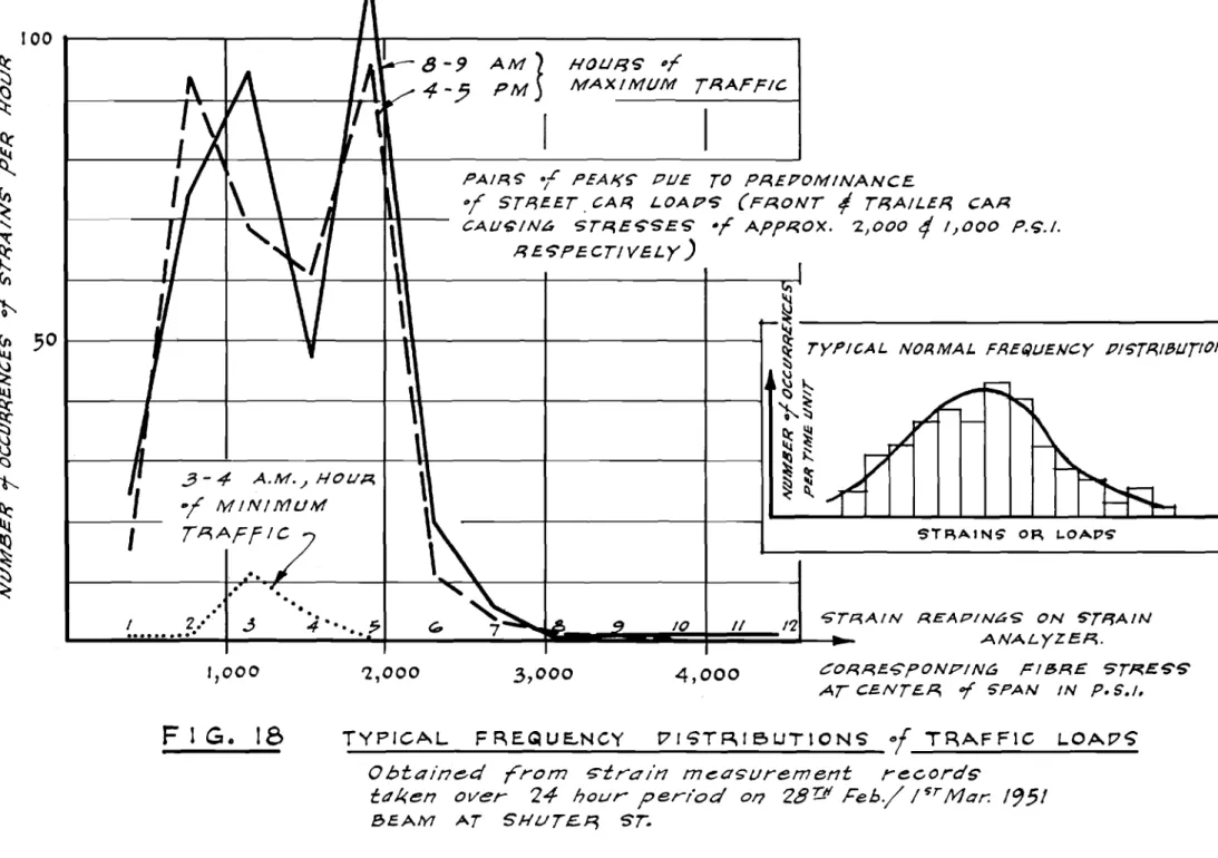
therefore, an attempt should be made to determine the frequency or probability of occurrence of heavy load combinations. This, in a general case, would mean making a statistical study of continuous records of traffic loads passing over the structure. If continuous records of strains occurring in a main member are taken, these would indirectly represent traffic loads. They can, however, for practical reasons, be considered in terms of
stresses, rather than strains or loads. If the results are plotted in form of a frequency distribution diagram a curve of
the type shown in the insert in Fig. 18 would generally be obtained. In this diagram stresses corresponding to loads of エィセ order of magnitUde of the design load in most cases are at the extreme right or probably even beyond the values that can
セ
7
=be shown by such a curve0 Consequently, in all practical cases
where records cannot be obtained over extremely long periods,
the frequency
or
very heavy loads may only be obtained by extrapo-lation of the curve. Extrapolating from frequencies of measured loads to the frequencies of extreme loads is difficult, however, and sometimes of doubtful value. This is especially true in a case such as the one in Toronto. When certain definite loadsbecome predominant, such as the weights of street-car::!, and ready-mix concrete エイオ」ォウセ the shape of the frequency distribution curve
varies greatly from the normal curve, which is obtained, for
ゥョウエ。ョ」・セ for rain storm precipitation9 wind pressures, etc. and
statistical rules cannot be appliedo The theory of probability,
エィ・ョセ is no substitute for the measurements of a great number of
actual loads, as no matter how much time was spent on curve
ヲゥエエゥョァセ the accuracy of the curve for extreme loads would be
uncertain. Consequently sound judgement has to be used without much quantitative help from the law of statistics.
(c) Fatigue
As is well ォョセキョL a structural member subjected to millions of repetitions of load may fail by rupture even though
the stress is below the elastic limit stress. This fatigue
failure is due to progressive fracture caused by the very gradual spre ading of minute cracks. The number of load cycle s which has to be reached before the possibility of fatigue failure has to be considered Ls , very r-o ughLy , one million. Since street-cars pass over each pair of stringers a sufficient number of times to
cause Rセooo or more axle loads a day and as the life of the road deck is about one or two years, the stringers come within the range where the fatigue strength is a decisive factor, as far as
the number of cycles is concernedo The magnitude of the stresses in the stringers, ィッキ・カ・イセ and even more so in the main beams, is, as will be seen later too small to indicate a danger of fatigue failure in the deck in question.
4.
STRAIN MEASUREMENTS ON THE TEMPORARY ROAD DECK (a) General RemarksIf the above general considerations are applied to the Toronto ーイッ「ャ・ュセ their importance can readily be ウ・・ョセ
because the design load consists of very heavy concentrations which are likely to occur simultaneouslv only on very rare occasions. The justification of the design load is therefore questioned. Frequency considerations of load alone9 however,
cannot apply to all parts of the temporary road deck, since
there are other aspects entering into the choice of the sections, for the soldier piles and the cap beams for instance, such as driving through hard soils with boulders and the resistance of earth pressure.
8
-In the light of these facts it was decided to carry out an investigation of strains occurring in the deck beams and some other structural elements of the temporary road deck. This work was done co-operatively by the Toronto Transportation Commission and the National Research Cowlcil. The Toronto
Transportation Commission besides assisting the National Research Council personnel also made available the following:
(1) Auxiliary equipment such as the special hut for housing the equipment during the tests;
(2) The personnel of the Testing Subsection of the Rapid Transit Department when needed;
(3) The use of the Soils Laboratory and of some of the work-shop services;
(4) The use of the crane car with crew for loading of the deck beams;
(5) The use of the automobile assigned to the Testing Subsection;
(6) The co=operation of the traffic inspectors during the loading of the deck beams.
The National Research Council supplied personnel to work on this project and all scientific equipment.
The majority of strain measurements for the subway were carried out on deck beams since they are the elements of
the temporary structure for which an improvement in the economy of design would be obviously most important. Tonnage of steel in the deck beams is the ァイ・。エ・ウエセ apart from the tonnage used for piles for キィゥ」ィセ however9 ウエイ・ウセ・ウ due to traffic loads are
not the decisive factor. Only a few measurements were made on one of the trusses which are used for the wider span of the
station sections of the subway. Because of the much greater amount of labour involved in the 」オエエゥョァセ 。ウウ・ュ「ャゥョァセ and
キ・ャ、ゥョァセ the trusses were abandoned in favour of I-beams with
knee braces.
The knee braces not only serve to reduce the free span of the I-beams but also act as partial shoring of the supporting piles against earth pressure. In other キッイ、ウセ they represent structurally one step in the transition from a frame to an arch with a corresponding reduction of bending movement. Appreciable stresses were therefore expected in the knee braces
エィ・ュウ・ャカ・ウセ especially in view of the fairly light steel sections
used for them; a number of strain measurements were made, consequent-ャケセ on these braces.
セ 9 =
The stringers represent the main longitudinal element in the deck which should be considered as a grid system for analysis. cッョウ・アオ・ョエャケセ when stresses in the deck beams were found to be low, measurements were also made on some of the
stringers in an attempt to investigate the distribution of load from a loaded main beam to the neighbouring main beams.
As all deck beams9 for economical reasons, have
constant cross-sections, measurement in the section of the maximum stresses was considered sufficient. Strain ァ。オァ・ウセ therefore» were attached at the centre of the span, which in most cases coincided approximately with the centre line of the street and of the street-cartracks. In one case measurements were also taken at the quarter points of tre span.
Stresses occurring in the deck beams consist of two parts» a static part due to dead load and earth pressure and a
superimposed dynamic part due to live load セエイ・・エM」。イ and motor traffic). Fbr the first part which» due to earth pressure, may develop very slOWly» a very stable type of gauge must be used, while for the live load stresses9 which are the more important,
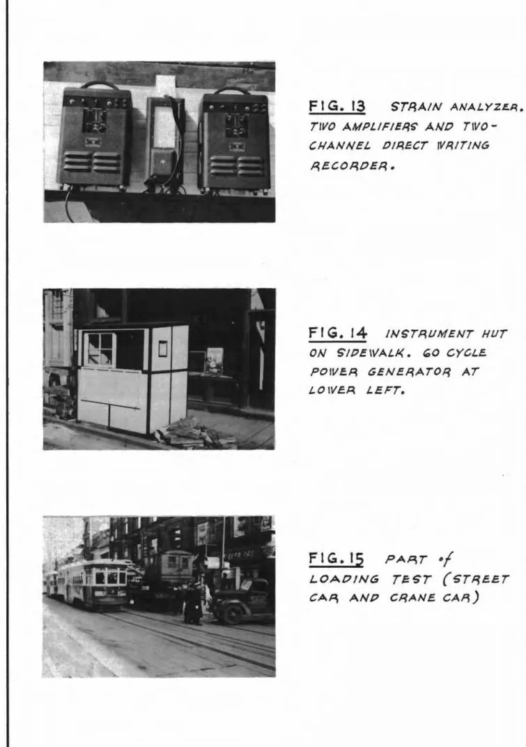
a type of gauge must be used which allows easy recording of the transient phenomena. The two strain gauges chosen were: an
8=inch mechanical extensometer (Fig. 13) and electrical resistance wire strain gauges, known as srセT gauges9 together with amplifiers
and a direct writing recorder (Fig.
14).
(b) Objects and Methods of Measurements
In accordance with the objectives already stated, of determining both the magnitude and the frequency of traffic load stresses» the two main types of strain measurements made were the ヲッャャッキゥョァセ
(a) Recording of strains in deck beams caused by very heavy loads (st re et e-c an weighed T"T.C. crane car and weighed ready=mix concrete truck); and
(b) Recording of strains caused by normal traffic (street-car and motor traffic) over longer periods of time.
The following two special strain tests, on one beam e ach , were also made:
(a) Determination of impact effect of slow and fast moving street-cars going over rail crossings on
strain in deck be am ; and
(b) Determination of effectiveness of knee braces in reducing strain in the main deck beams.
- 10 =
In addition, the following three special investigations were made:
(a) Determination of the continuity effect in the stringers; (b) Observation of the simultaneity of heavy loads
(street-cars and ready-mix concrete trucks) on one beam during a concrete placing operation; and
(c) Some observations of strains caused by earth pressure. (c) Experimental Results
(a) Strains in Deck Beams Caused by Known Loads
In order to determine the maximum stresses in the deck beamsg a combination of loads corresponding closely to the assumed
design load was used. It was found, however, that due to the traffic on Yonge Street it would be too difficult to position the combination of cars usedg consisting of a ToToC. crane car, a T.T.C. street-car,
and two or more heavy trucks all at one time on one beam. Strains caused by these loads acting separately were, therefore, measured and added together, using the law of superposition, except for the crane car and the street-car the load effects of which ware measured simul-taneously. The law of superposition may not be strictly valid for the deck because the continuity effect of the stringers and the deck timbers may contribute to a progressively increasing distribution of the load on to the adjacent beams. Should this be the case, howeverg the
resulting sum of strains (or stresses) could only be greater than the strain (or stress) produced by the combined load, and therefore the deck beams in reality would be safer than would appear from the test results.
According to the specifications of the Toronto Transportation Commission, the design load for the temporary street deck consists
briefly of the following:
(1) A train on each street=car track, consisting of two or more 50-ton double truck cars, 40 feet long. Each axle load shall be 12.5 tons; axle spacings shall be 5, 20, and 5 feet; plus
(2) A column of trucks on each traffic lane of la-foot width, consisting of one 20-ton truck, preceded and followed by 15-ton trucks; the load on the rear axle (or axles) shall be 4/5 of the total truck load and the spacing of the trucks shall be
44
feet.Considering one deck beam alone in a simplified way the desi&n セッ。、 consists of the following double axle loads acting mainly on one beatn
1 Truck
16 t ons 1 Street-car25 tons
1 Street-car
25 tons 116 tonsTruck
The load used in the experiments, although varying slightly from test to testg was approximately as follows:
1 Truck
17 tons 1 Crane car
33
tons I Street-carQWセ tons1 Truck 17 tons
11
-It can be seen that the magnitude of the test load with regard to its effect on bending moments was reasonably similar to the design load. Figure 15 shows part of the loads during a loading test.
The strains and resulting stresses measured in the various beams under the above-mentioned loads are presented in Table ャセ whereby the following load cases are shown separately: one street-car north-bound; one str..ee t-car south-bound; crane car north-bound; crane car south-bound plus street-car south-bound; one concrete truck north-bound; one concrete truck south-bound; the last three loads combined. The maximum stresses obtained range from
5500
p.s.i. to8500
p.s.i. Figure 16 shows areproduction of two of the test records obtained during load test.
(b) Strains Caused by Normal Traffic
For each beam investigated strains caused by
normal traffic on Yonge Street were recorded for various lengths
of エャュ・セ in order to obtain an idea of the frequency of occurrence
of various loads. For the beam at Shuter Street a continuous twenty-four hour record of strains caused by all traffic was obtained. Figure 17 shows the distribution of strains (grouped by the numbers of lines of chart deflection) over the twenty-four hour period. Figure 18 presents the same measurements in a different manner: for typlc-al hours of the day, the number of occurrences of the various strains is plotted. The predomi-nance of the strains corresponding to the two loads of the
street-caffi is evident and explain why it was stated in the
paragraph "Statistical Approach to the Design Problem" that the laws of statistics could not be applied here. Figure 16 shows the characteristic two pairs of strain peaks caused by the trucks of the front and the trailer car.
(c) Effect of Impact
The effect of impact is usually greatest at street intersections where street-cars passing over the rail crossings cause vibrations of the deck. This effect was determined in one case (for a beam at the intersection of Yonge and Wellington Streets) by comparing the strains caused by a street-car crossing the intersection at full and at very low speeds. The increase of strain due to full speed operation over the strain caused by static load キ。ウセ for this beam» in the order of 30 per cent for one street'-car alone. The impact effect of mul tiple loads was not determined. It was observedD however» that the heavier the load
combination the more of its parts were moving slOWly or even stationary. cッョウ・アオ・ョエャケセ the impact effect decreases with increasing loa.d,
12 -(d) Effec"tiveness of Knee Braces
OWing to the fact that it was possible to test one station section beam (north of Wellington Sto) in three different 」ッョ、ゥエゥッョウセM with knee braces9 with one only, and
with none-- under normal traffic9 an approximate idea of the
effectiveness of knee braces in reducing the centre span stresses has been obtained. It was not possible, however, to load the beam with the heavy load combination for all three conditions. Table 2 shows the stresses as determined from the strains
measured for the loads of one street:-car north-bound and one
ウエイ・・セ south-bound for the above=mentioned three conditions.
The difference between the strains caused by the north- and south-bound_street-cars is due to the fact that the strain gauges could not be mounted exactly in the centre of the セー。ョL because of a spreader beam. The gauge was 10 inches east of the centre of the street as defined by the atreet-car rails.
The east knee brace was removed first as part of construction operations. The west knee brace was also removed while traffic on Yonge Street was still maintained. It was only cut near its lower end by an acetylene burner and in such a manner as to become effective under heavier loads. The gap created by the burner was just wide enough so that it would not be closed under the deflection caused by the load of one
street-care
The increase of stress due to removal of one knee brace was, on the average, close to 100 per cent; removal of both knee braces was approximately 200 per cent. If this same increase is applied to the stress due to the maximum lOad
combination (692 00 p.soi. obtained by superposition) a maximum
fibre stress of close to 199 0 0 0 p.s.io would have been reached.
The stresses in one of the knee braces of the above= mentioned beam were also measured•. The conclusion that the knee brace would experience the highest stresses near mid-span on the
underside was confirmed by taking spot readings at various points of the knee brace by means of the 8-inch mechanical
extensometer. Electrical strain gauges were then attached only at mid-span of the brace and the results shown in Table 2 were attained by the gauge on the underside.
The maximum stress in the knee braces caused by the usual heavy load combination totalling 84! tons, was セUP p.soio compared to 6,200 p. s , I , in the de ck be am. Both the se figures were obtained by superposition. Consequently, the knee "brace was underdesigned compared to the beam, in fact considerably more than appears from the comparison of the stress values because of the danger of buckling present in the knee brace.
=
13
=(e) Continuity Effect of the Stringers
The low values of maximum stress obtained in the deck beams lead to the conclusion that these beams receive considerable load relief, compared to strict simple beam action, by distribution of load, to varying degrees, to the adjacent beams through stringers, rails, and timbers. This load relief
is caused by the fact that the greater deflection of the loaded beam except when all beams are equally loaded which is never
the case with the spacing of beams and loads used on this
project results in a tendency of the stringers, rails and partly also the timbers to bridge over this beam. The partial fiXity of the ends of the deck beams (welded brackets) also contributes to the load relief. Beaause of'the spacing of'the beams
and
loads on this project, it is never possible for all beams to be loaded equally.The stringers act partly as continuous beams through the webs of the deck beams to which they are welded by means of bracketso The transmission of bending moments through the web of the heavy deck beams is, of course, impeded by the torsional stiffness of the deck beams. As can be seen from the strain lines of Fig. 19, however, some negative moments do act in the non=lcaded spans adjacent to the loaded span. The strain
readings were taken by means of an 8-inch mechanical extensometer on two lines of stringers over two spans, at the quarter= and mid-span pointso The load used consisted of the tッtセcッ crane car loaded to approximately 32 tons per truck, ioeo, exceeding
the specified design load by
7
tonso For the measurements the deck planks covering the ties were removed and the personreading the extensometer was stanqing just below the deck on the partly completed backfillo
The maximum stress recorded in the stringers was
9,400 pos.i. which is 25 per cent below the value of 12,600
p.s.io computed for the same steel section acting as a simple beamo The greatest stress measured in an area of negative moment was approximately 1,000 p.soio
From the magnitude of strains in the stringers for the load stradling a deck beam it can be seen that always a considerable portion 0f the load of a truck) of a 。エイ・・エセ car or crane car is distributed to the adjacent beam.
(f) Coincidence of Heavy Loads During Concrete Placing The likelihood of occurrence of heavy load combinations was greatest during concrete placing operations, when, in addi tion to two street-cars crossing on one beam, there might be two' イ・。、ケセュゥク concrete truckS standing on the side 1 ana s on the same beam. It is not surprising that during the accurate observation made of one complete concrete placing operation for a roof section, approximately 100 feet south of Dundas Street, during about five' hours, not once was a beam
=
14
=This. becomes understandable when one considers that only once every two to two and one-half hours do two street-cars cross on
the same beam which would double the strain caused by one
street-car. This was established from the records obtained by means of the strain analyzer equipment.
During the 。「ッカ・セュ・ョエゥッョ・、 observation of load combi= nations occurring 、オイゥョァセ concrete placing operation the
following frequencies of loads were found:
2 street-cars plus 2 concrete trucks exactly on the same beam - 0 times.
I ウエイ・・エセ」。イ plus 2 concrete trucks exactly on the same
beam - 0 times.
1 street-car plus 2 concrete trucks with centre of rear
axles at average distance of I ft. from the beam - 0 times. I street-car plus 2 concrete trucks average distance of
2 feet セ once.
I street-car plus 2 concrete trucks average distance of 3 feet = twice.
1 street-car plus 2 concrete trucks average distance of
4
feet = 8 times.I street-car plus 2 concrete trucks average distance of
5
feet - 7 times.It ヲッセャッキウ that even during concrete placing ッー・イ。エゥッョウセ
load combinations consisting of two street-cars and two concrete trucks acting simultaneously on the same beam are extremely イ。イ・セ although definitely possible.
(g) Strains Caused by Earth Pressure
The attempt to determine the axial load in deck beams and also in steel struts by means of the mechanical
extensometer was only partly successful. Taking readings on beams Which were almost inaccessible under the street deck as well as obtaining the zero readings was often very difficult. The inaccuracies inherent to ャッョァセエ・イュ measurements (deterio= ration of the small drill holes in the beams9 etc.) affected
the quality of the readings. Some difficulties were also
encountered at first due to the fact that the extensometer was made of ordinary steel (and not of Invar as indicated by one
authority) 。ョ、セ エィ・イ・ヲッイ・セ was found to be sensitive to the heat of the hands of the person taking the readings.
= 15 =
In Fig. 20 the results of the strain measurements on the knee-braced beam north of Wellington Street (Stations 115 and
44)
are shown. At the time of the last readings (when the slab and the walls of the subway had been completed) the axial stress in the beam had reached a value of the order of magnitude of 5,000 p.s.i.9 corresponding to a force of 130 tons.Out of general interest the results of some strain measurements taken on steel struts, in the same 。イ・。セ are also
shown (Fig. 21). The load on the struts, varying roughly between 20 and 30 tons, was not very large. This is in line with the relatively late installation of the struts. In view
of the stiff plastic nature of the soil, it was possible for the contractor to determine the need. for struts in most
locations on the basis of measurements of the distance of opposite soldier piles by means of a measuring tape. If any excessive
inward movement of the piles was detected, struts were installed. The danger of buckling in a horizontal direction of both the deck beams and the struts, was considerably reduced by effective use of spreaders and tie rods, and also of the stringers
connecting the deck beams.
5.
DISCUSSION OF RESULTS (a) Low Maximum StressesThe two most striking aspects of the results are the low value of stresses obtained under a heavy load combination corresponding closely to the design load and the infrequency of heavy loading by the traffic on the deck. It is believed that the low stresses in the deck beams were principally due to the fact that they do not act as simple beams. Two reasons for this are:
(a) Due to the load relief resulting from the continuity effect of stringers, rails, and deck エゥュ「・イウセ the maximum load actually carried by one beam does not correspond to the combined axle loads acting on this beam;
(b) The welded connections between the deck beams and the cap beams and piles introduce some end fiXity into the beams.
The amount of axial load due to earth pressure that is transmitted from the soldier piles to the deck beams is limited by the conditions present. The earth pressure acts mainly as a horizontal load on the piles, which are supported at the top by the deck beams, at the bottom by the embedment in the soil and, in some cases, in between by struts. The flexural strength of the steel piles, combined with their unsupported vertical span below the deck beam, limits the reaction in the deck beam and, therefore, the stresses dne to earth pressure. An estimate for an average deck beam, with struts 10 feet below it,
= 16 セ
yields an average compressive stress of less than 39000 posoio even when the piles are loaded to yield (40pOOO posoio fibre stress)a Actually this force is introduced along the bottom of the deck 「・。ュセ resulting in a favourable eccentric loading, Le 0 セ a tendency to compensate the stresse s due to the deck
loada In knee-braced deck beams the axial load can become greater because the knee 「イ。」・ウセ in assuming part of the role of the ウエイオエXセ transfer a greater percentage of the earth pressure to the deck beam,
(b) Infrequency of Heavy Loads
As the records of strains in the deck beams caused by normal traffic show, the other notable aspect of the results is the infrequency of large strains or stresseso It is probable that the majority of the deck beams on this project will never normally experience stresses exceeding three-quarters of the stress obtained under the heavy experimental load combination used p and be
sUbjected to this stress only very ウ・ャ、ッュセ ioeo, only when the TaToOo crane car is used on Yonge Sto In the absence of the crane 」。イセ the probability of relatively heavy loads acting simulta-neously on the same beam is greatest during concrete placing operationso Even then, ィッキ・カ・イセ very few beams will experience the f'u l I combined load of two stree t-cars plus two full concrete
エイオ」ォウセ as the observation of vehicle movements made during a
concrete placing operation showedo
(c) Improvement of Economy in Future Designs
One of the principal objectives of this study was to see in what direction improvements might be effective in future designs of the same type of temporary deck structurea The design loads used for this part of the TaToOa Subway project were neces-sarily used in the absence of such specific information as this Report presents0 Nothing in this Report is to betaken as any
indication of criticism of this quite proper approach to an unusual design problema sィッオャ、セ however, a similar temporary
structure have to be designed in the ヲオエオイ・セ in Toronto or elsewhere, it does now seem possible for some additional economy to be
introduced safely into the proportioning of the deck systemo In the first place, it would seem practicable to make Bome allowance, possibly to the extent of a reduction of 30 per cent in the assumed design load on any one 「・。ュセ for the continuity which obViously exists even in such a temporary structure as that which was investigated in Torontoo
To allow for the infrequency of heavy load combinations a further decrease of the design load would seem possible because the probability of occurrence of the heavy load combinations is small a In fact a considerable saving might be obtained by
regulating the movement of the ToToCo crane 」。イセ by issuing
instructions to the driver with regard to passing other vehicles on the street deck o If, in this wayp the driver were not allowed
17
-to pass a street-car and two heavy trucks at the same エゥュ・セ
consideration of a further reduction in the design load would be possible. Even if the driver of the crane car neglected to observe the instructions, the factor of safety inherent to the allowable design stress would be ample to take care of the slight overloading.
The investigation of the effectiveness of the knee
「イ。」・セ showed the great benefit obtained by these braces in
reducing the 「セョ、ゥョァ moments in the deck beamso The knee braces would seem, therefore, to be of great value in saving steel in the deck beams, possibly also in the box sections of the subway, when circumstances allow their use. The knee braces also help to reduce the need for strutting by transferring a greater percentage of the earth pressure from the piles to the deck beams. This force should also be taken into account in the design of deck beams for similar structures.
ACKNOWLEDGEMENTS
Much assistance has been received by the author during his work. It would be impossible to list all those who have given a helpful hand in the work itself or in the form of suggestions during discussions. To all sincere gratitude is expressed.
Special mention, however, must be made of the
co-operation of the Toronto Transportation Commission and the staff of the Testing Subsection of the Rapid Transit Department in particular, without whose help this work could not have been carried out. The co-operation of the General Contractor for S=l and S-2, Pitts, Johnson, Drake and Perini, is also acknow-ledgedo Gratitude isaleo expressed for the many helpful :sug-gestions and the loan of some equipment which was received
from the staff of the Research Laboratories of the Hydro-Electric Power Commission of Ontario.
The author wishes to record his gratitude ror the continued assistance, encouragement, and understanding received during this work from Mr. R.F. Legget and a large number of the staff of the Division of Building r・ウ・。イ」セッ
APPENDIX A
Equipment Used for Strain Me asuremenl;s Extensome ter
The extensometer, in principle, is a device for measuring the change in distance between pairs of small holes drilled into the steel structure. The extensometer, shown in Fig. 13, consists of two conical steel points mounted on a metal frame, which carries a dial gauge actuated by a lever. One of the two conical points is fixed, the other movable over a range of 3/100 inch. This movable point is part of the lever which actuates the dial gauge with a lever ratio of QセQPN Each unit on the dial gauge, which is graduated in 1/1000 inch,
therefore, represents a movement of the point of 1/10,000 inch. With a gauge length of
8
inches, this is a strain of12.5
micro inches/inch, or a stress of375
pounds per square inch in steel with the usual modulus of elasticity.As the Metzger extensometer is not made of Invar but of steel, it is sensitive to temperature changes. If, however, the coefficient of thermal expansion of the extensometer is the same as that of the structure and if the extensometer is at all
エゥセ・ウ at the same temperature as the structure, no correction
of the イ・。、ゥョセウ is necessary for temperature expansion. A "standard bar for reference readings should, however, be used in all cases. It should be laid on the structure for a suffi-cient time to allow it to assume the temperature of the structure. The standard bar is also used to compensate for possible changes in the length of the extensometer which might be caused by
accidental bending of the conical points or in case of repairs. The punch bar, which is supplied with each extensometer, was used as standard bar by taking readings on the hole s drilled for this purpose near the set screws.
Electrical Resistance Strain Gauges
SR-4
strain gauges were used for picking up strains in the deck beams due to traffic loads. This type of gauge operates on the principle that the electrical resistance of a given wire changes with a change in a length such as may be produced by tensile or compressive stress of the wire. A stretching of the wire results in an increase of electrical resistance due to both the increased length and the reduced cross-section. This change of resistance, other factors such as temperature remaining constant, can be calibrated in terms of strain. The gauge consists of a grid of fine alloy wire, bonded to a paper base, about the size of a postage stamp. The gauge was bonded to the structure at the desired place, after the steel surface has been prepared by means of a grinder and various grades of emery paper. The lead wires of the gauges were soldered to the wires of a cable leading to the recording equipment and the gauge covered by a coating of wax to protect2A
-The SR-4 gauge will respond to compressive as well as to tensile strains. Since the full length of wire is bonded g the wire cannot buckle and does not need to be preloaded. As already mentioned g the stretching of the gauge results in an increase of resistance due to the increase of the length of the wire
ana
the decrease of' the cross-section. It has been found that the change of resistance is larger than would be expected from the pure geometrical change of the wire. The magnif'ication f'actor expressed 「ケセrOr ッカ・イセlOlァ where R means electrical resistance and L length of the wire» is called the gauge f'actor. It varies considerably for dif'ferent materials» and slightly for each batch of manufactured gauges. Therefore each package of gauge carries a value for the gauge f'actor whichg for the common type of' SR-4 gauge used in this project g is around 2.05.Naturally some form of temperature compensation has to be employed in order to eliminate changes of resistance of the wire due to temperature changes of the wire and due to
strains in the structure resulting from thermal expansion. For this purpose a second SR-4 gauge g known as a "dummy gauge" is mounted on an unstrained piece of' the material of the structure
located near the "active gauge" and used in the compensating arm of the Wheatstone bridge of' the measuring circuit.
The two pairs of lead wiresj) from the active and the dummy gauges» are carried as a セィゥ・ャ、・、 four-conductor cable to the recording equipment located above ground in a small hut (Fig.
15).
This equipment g which consisted mainly of' two bridge balancing units and amplifiers and a two-channel direct-writing recorder g was chosen after a careful study of commerciallyavailable instruments. The convenience of' direct writing
recording (in contrast to photographic recording) and the wide range of paper speeds g were the main factors in f'avour of the
choice of the strain analyzer used because it had been established that the frequency response of the direct writing method was
sufficient.
The strain analyzer contains two arms of a Wheatstone bridge, connected to a high frequency carrier supply (2,000 cycles per second). The other two arms of the bridge are the active and the dummy gauge. The bridge is balanced by the resistance and phase controls on the panel of the amplifier. The bridge output is amplified» demodulated and fed into ad-c.
amplifier and f'rom there into the magnetic pen motor of the recorder. When the active gauge is subjected to a strain» the "out-of-balance" of the Wheatstone bridge shows as a deflection of the chosen zero-line on the chart of the recorder. The strain analyzer
18
calibrated directly in terms of strains, so that for the SR-4 strain gauge of 120 ohms, strain can be read directly in micro inches per inch from the chart deflection. The overall gain can readily be checked by a control on the amplifier whichconnects an internal calibrating resistor into the bridge circuit and be adjusted if necessary. For various applications of the
3A
-equipment with different orders of magnitude of strain, an attenuator permits a choice of sensitivities, from 10 to 2,000 micro-inches per inch corresponding to a deflection of one
line on the chart paper, which has a width of 40 lines. Magni-tude as well as direction (tension or compression) of the
strain can be read from the chart and also both static and dynamics strains (up to approximately 80 to 100 cycles per second). The speed of the chart paper can be selected easily by a gear shift from the following values: 50, 250, 1250 mm!hour, 5, 25 and 125 mm/sec. corresponding roughly to 2, 10, UPセ 720,
セVPP and ャセooo inches/hour. The strain analyzer operates on
60-cycle power. Since Toronto is still in the 25 cycle area, a portable gasoline engine driven generator was used as a power
-,. ---r---
-SU81vAY 5£CTION sox ,leT/ON l>OX ,L(.TION 80X SlCTION ,TATION .£(.TION HATION ,lCTION
セッ・atioセG AT ,NI/TlR ST. AT |jiャlャinセton 'T. AT DUNDAS ';t;. NOIITH OF ..,£LUNGTON NOIITH OF QUllN ,r.
'TATION IJ8 ..セL /14'"Jf /44 +()O 1/6+ 44 IJ1 .. '0
rrrs I/!;I.AM I &!.AM I l>LAIItI I &£AM (NU l>.I,ACl. J:¥!j
'TUL ,leTION 16' I.. 182* $i'V 13O· 36' ... 182- 36' ... IS2" VセV 4lNGTH /2'1.. 99"
SPAIU 3#' '7'- 10· u,' $4'
,PACING OF 8l.AM, 12' SOUTH " NOIITH 12' 12' IZ' 11'
OAT! or TUT 111 MAil./951 !1I 18 JAN. 195/ 17 JilL YI 14 AIl(;. Sf 12 occ. /950 17 JULYI 17AI/{i.51 TYP£ 01' 5 T/lAIN 6AI/(;£ 5/l-4 ,A-I 511-0/, A-I SIl-4, A-I SIl-4,A-1 '/l-4I A-I
6Al/ti£ FACTOIl 1.0'5 '2.05 1.05 1.05 1.05
tiAUG£ TO lXTIl. FIBIlE 4' I'ROM TOP 4' FROM TOP 4' FROM TOP 4' FROM TOP ct NTER -ISOTTO#!CNOI/P "AUGl TO (OF Sf.AM 2 '(lY!>T) -z"(VHT) /0'(lA'T) ,'. " (!MT)
if1I0AO TO tl01' BlAM 1'(I"£5T) /I' (I"iST) 1j'(1II£ST) INSTRI/MOIT ATTlNUATION
'TIIAIN'IlINf. ON CHAIIT c 10,," IN/INCH lOP IN/INCH /0,," IN/INCH Ooセ IN/INCH 1O"u. IN/INCH 'TIIHS' IセinA ON CHAIIT - 300 PSI 300 PSI 300 PSI 300 PSI 300 pセO
LOAP5 ON PlC/( 8lAM STfl.AIN STIILH AT STRAIN STIILH AT STIIAIN STII£H AT STRAIN STII£H AT STRAIN STill. . AT
o
(LINES) gaセᆪ UTII.1i (LiNtS) GAU(;! £1TII1 (liNts) 6AUGE lXTJ.F. (lINU) tiAUu!tmr (iINU) uA1/6! £XUI' (p,1) (PSI) HpセOI (PSI) (PSI) (P'I) (PSI) (p,/) (PSI) (m)I STIU£T CAli NOIITH
セoaoᆪpL QWセ TON5/TIII/CX) S/1 16.0 1100 Jr. 10SO IHO 4f/-; 13.0 1750 J "'0 1/.0 4Y-z IHO /!HO I STRUT CAR SOUTH
sh
(LOAO!O, 17h TONG/TIII/el<) 1650 110e 3 gOO 10.0 5 1500 1950 1 000 750 .J gOO 900 I (.RANl CAli NORTH
(LOAPlO, .33 TONS/TI//X/() IJ ,900 sooo セヲON 1HO "00 IJ ,gOO 5000 10J.1 3150 4050 I'Z '600 3600
aAN! CAR N+S77,!!T CAlis.
17?1 lOY:
(LOAO!O, 50Y-: TONS) • U50 67.0 ".0 セoso 12 J600 46.0
CONCIl£T£ TRI/CI< NOATH
(ON 510! LAN!. 17 TONS) '1 '00 775 Gャセ '7. 850 '1 "'0 750 3 !JOO 1/50
"'
CONCIlETE TIlUCX SOUTH A'.""" (ON .IP! LAN£, 17 TONS) '1 fiOO 775 If!: J50 600 I JOO セッッ 1
MAX. LOAO !LAST THlllE) A"-Vltla'
XTセ TONS(8Y SUP£IIPOSJ 11/1 04,0 8300 14J4 .-275 >500 12 "00 H!1£ I. 4800 .100 10 6000 .000 Iセtiャut CAli NOIITH, SLOW
Qセ
(FOR MIN. IMPACT) • 825 1050
I STR£IT CAA fOUTH, SJ:Ol...
Qセ
(Fall MIN. IMPACT) • 67. セNo
tABLE. l SIBf..$SE.S IN DE.CK M,AM$
Shuter St. 4 Dund=. セアオッNイ・Z
Trucle. Street Car セエイ e et Co.r Tr.,..\<'
"---,
...---ell,,!,,!
'l$' ,
t!t?Ci"
I"ftセ
セ
Stro.,n qQ.u,lle) t-lorlh Of w・ャャゥャGャセGイエッョ St.: IE: Truek North Of Queen セN : Tt"ueK s " セ of R.oa.dStreetCo.r , セイ・ et Co.r Trud<.
.--'---. . . - ' - - - .
TrucK.
SLlBtVAY <SECTION t:;'tation section
LOCATION North "f IVellination
5treet
STATION 1/3 +
41-TyPE I beam, knee - brace d
" : # " #
-5TE£.L SECTION 8eam: 36
w:-
/82, knee bracee : 8w=-
40f "
knee bra c e-s 37'-/0"
<SPAN Tota/
57
-'2 セ between5'?ACIN6
"I
PECK 8EAmセ /'2 /STRAINS'
4
セtreDsGeN・Z[[ INPECK BEAM IVITH BOTH KNEE BRACES PEep< 8EAM PE.CK, BEAM
ONLY ONe. BRACE. 80TH
PECI< L3EAM KNEE. 8RACE (£ BP,ACE REMOVEP) BRAe£.5' REMOVEP
5TRAIN 'S'TRE5'S AT STRAIN STP,E<;;'S AT STAAIN STRE.SS AT stセain STRE.'SS AT
LlNE..<;;*Vauセe pSI EXT/(.P'31F. 1.1NE.';; 6AU6£ EXT/.? F.P51 PSI LINE.5' i3AU4EPSI sxre.PSIF. LINES i5AlJ6E.r e : EXTR.F.
PSI
/ STREE.T CAR. NOP,TH 3 セッッ 1/50
7
1.500 15°03%z
1'50 '2100 8 '2400 3100(LOA[)C.t? /7J2 TONS' pER TRUCK.)
/ STREET CAR £ouTH 2 (000
:I..2.E.
3jz 1°5° 1°5°4-
/700 15°0 セjR 195 0 25°0(LOA1?E.1? QWセ TO,vt;' fJEP. TAUCK) セ
...,
1 CAANE CAR NORTH QPセ 31.50 4 0
5
0 14 4'200 4'200 83% 167%(LOAI?EI7 3.3 Toll/'£> ,PER TRUCI{)
I \
II
I CRANE CAR N. -I- I 'f;TRE£.T CAP, 12 3600 4(050 i_セ 46
5
04
rP5°
100'1. I "\
2'25%
(f.OAOE.t7 50jz TONS)
セ
V
/ CONCRETE. TRucK NOP,TH 3 セッッ 1/.5 0 ;J 27°0 2700 INCAEA5'E
of"
STRAINS(ON sloe LAAlE.,
/7
TONS) COMpARE.1? TO BE.AM/CONCAETe taカ」セ 50UTH / 300 400 4 /200 /200 lVITH 80TH KNEE BR,ACEt;'.
(ON 5'117.E LANEJ 17 TON';)
セ 5EE TABLE. 1
MAX'. LOA17 LAST THREE.., BY /0 4800 セGRPP 7.8!2 8550 855°
SUPERPOSITION 84f2 TONS'
l3c>arn w. Pile> 12" W-65# a' On C(!>ntc;>rs. ---f'H S'_,3'f .\.. .:J'_;'I Sr:rUT 12' セ /2.' On c・ョエセイウN 3" tOイョAクセイ L0,'1{IIr'/l' L...--I 9 '- /'
----I..
5'-.3 " NNlNNUGMGMセGセヲMMMMBBNM]MM]MMMエ⦅MMMMセMMMMMMセ 4'_OH Wale /4' l¥:Bea.m 、セ[ IV /10#(-300# For Lat;!1er Spans)
12' On Ce-nters. I - - - ---j -.',,' :.' • ,i't,.. • • セMMMGMMMMMMMMMMMMZN I ..,'' , r - - - - - - - - --r-->, .• Iセ • -: ' ..' • : '\J \ -, I
l-.
o <, " i'-... FIGURETYPICAL BEAM CONSTRUCTION FOR BOX SECTION OF SUBWAY
SCALE
I' It 1'1 ii' I o I '2 3 45FT.
For Dt:!'tai/s ェセBL Also fI/i- 1 . I::: セ 'I() t»
..
r '.
" I I ." , ,.
.,''.
..
" \ セ.
\. , I.,.
1 Oセ " . ,..'
セN セセ
,. I II II II II II :1 >.3;/0' 52GMQZセ n • III 11 ,---,--, 1 1 - ' o I 2. !> "\- , FT. 5CALE FIGURE 2. MMMセMMMLMMMEXAMPLE OF" BEAM WITH KNEE BRACES. EARTH SUB - GRADE
&eam <3,,"
we
jdZ"# XイqcZZセ o· W- 40 セ /2. '4-" I *f".';.' P, ,. , </v, , " ,p-, I , . . . . , '.
.', . 1セ , _ .. G:J-STrvt 12"W: 5J '"12'On cセョエ・イMウN
/4"W' 78*
IG'>i/tiJ"x!;i Plat",. (Driv.. n)
• ' . 1'.'
.
セ,.
"-, ' : r;:. "1' • , 1>. t'. • p- • po " a'" II' p.' " 2' セ ' I ;;.. - - - , , ;,ZセLi I ,' " ,t>"セNG I' II II [I ,I II ,I [I Ii II po • . . l» .-,,.---. '(>.p. e- o , FIG.3EXAMPLE OF TRUSS" ROCK SUB-GRADE SCALE
セ r r-I
FIG. 4
ORIVINGf
SOLl7IEA PILE5. (STEE.L H PILes)FIG. セ E'XCAVATION
of
TOP LIPT ANP EXPOSVAE:. "f" ' UTILITIES'.
FIG.5 PILE.5 l7RIVEN TO
REFuSAL (8£0 ROCK AT
'20 FT. O£pTH.
FIG.
7
UGvヲGiGopNtinセVTILITIE;S f3Y TIMl!JER5' PQ,IOf:l, TO SvGI'eN171N6 THeM i.JNPER THE. ROA/?
aec«,
PARTof
plL.•E. 'ii' CUT AT COR.RECT LEVeL..
FIG. 8
PLACING.f "" IIセr
BEAMS ON CAPPED 50/../JIE.R PILE..S AN/J7"
12""I'2"TIMBER PLANKING.F
r
G. 10 TIMBeR PLANKIN(;cur
TO LeNGTH. Pl.ACING.;-tieセ AND RAIL!;. NoTe
Sl/S'peNPE.1? ivat・セ MAIN
FIG.
2
GE.NERAL VIEW#If
CONSTRlICilD.N·f
PECK.NOTe PART
11/
STAINGeRS IN PLAce LJNOEA CENTER I.ANes.FIG. 11 TEMf'ORAAy AOAO
peCK GOMpLerep. NOTe
IN5'rALJME.NT
uur
foセ STP,A/N Me.ASURE:.MENT"!; AT RI6HT.fQguセeNN
1'2.
FIG.
rs
STAAIN ANALYZE-A.rlVo amplifierセ AN"
TIVO-CJ.lANNEl
omecr
WRITING PtE.CO,qlJER.Fr G. 14
inセtaument HUTON S/PE\VAL.K. GO CYCL.E. POIVEA GENERATOR AT
L.OIVE-A L.EFT.
FIG.15 PAp,T セヲ
LOAOING re