THE EFFECT OF PRINT STYLE ON
MECHANICAL AND MICROSTRUCTURAL PROPERTIES OF
STRUCTURAL CERAMICS FABRICATED VIA
THREE-DIMENSIONAL PRINTING
by
Bugra Giritlioglu
B.S. Materials Science and Engineering, 1993 Cornell University, Ithaca, NY
Submitted to the
Department of Materials Science and Engineering in Partial Fulfillment of the Requirements
for the Degree of MASTER OF SCIENCE in Materials Science and Engineering
at the
Massachusetts Institute of Technology February, 1996
© Massachusetts Institute of Technology, 1996. All rights reserved
Signature of Author
Department of Materials Science and Engineering January 19, 1996 Certified by
Michael J. Cima Norton Associate Professor of Ceramics Thesis Supervisor Accepted by
Michael F. Rubner iAHUSETTS INSITITETDK Professor of Materials Science and Engineering
THE EFFECT OF PRINT STYLE ON
MECHANICAL AND MICROSTRUCTURAL PROPERTIES OF
STRUCTURAL CERAMICS FABRICATED VIA
THREE-DIMENSIONAL PRINTING
by
Bugra Giritlioglu
Submitted to the
Department of Materials Science and Engineering on January 19, 1996 in partial fulfillment of the requirements for the degree of Master of Science in Materials Science and Engineering
ABSTRACT
Three-dimensional printing (3DP) is a solid freeform fabrication technique that utilizes ink jet type print heads to place binder droplets in a computer-specified pattern onto layers of powdered materials, gluing the powder bed on a point-by-point basis. The mechanical and microstructural properties of green and fired parts depends strongly on the specific manner in which droplets are deposited onto the powder bed, i.e. the print style. In particular, line spacing, layer height, droplet placement, line arrangement are among the important parameters.
The effects of print style was investigated by printing 3 sets of bars out of spray dried alumina using 3 print styles, viz. the linear raster, staggered, and checker styles. Each set consisted of 3 types of long rectangular bars oriented along the 3 orthogonal axes of the 3D printer. Four-point bend testing was performed on as-printed bars as well as Cold Isostatically Pressed (CIP) & fired bars. The dependence of Modulus of Rupture (MOR) on direction and print style was determined. Shrinkage due to CIP along the 3 axes was quantified. SEM and optical microscopy was used to characterize microstructure of green and fired parts. Current CIP technique was modified to allow CIP of complex shapes with hollow interiors. A prechamber part was fabricated using this new technique.
Green parts were strongest along the fast axis, weakest along the z axis, with an MOR ratio of ~3. WIP & firing virtually eliminated the defect/strength anisotropy observed in as-printed green parts. The staggered style reduced the number and size of 3DP-induced intergranular porosity by preventing line merging. The staggered bars yielded the highest fired alumina strengths (-400 MPa). Proportional deflection improved green strength along the slow axis. The average strength for silicon nitride bars was -570 MPa.
ANAGRAMATICALLY YOURS,
I am really sorry about the small font but I had to do it to correct a big big page number error somewhere else. This might save my life...
Can youfigure out who the following are?? If not, see solutions at the end
To thank Professor "I am chemical," a.k.a "I am a chic male" I would like very much (1) Over the past two years, for all his guidance, and for beyond graduation agreeing to hire me , thereby, for the time being, from the horrors of the Turkish military saving me, I owe him a lot! Out of the way is this degree thing now. Like, forward to a fruitful and less stressful collaboration I'm looking, I mean, like, some fun time together. (English or no English, is that the question??!)
I would also like to thank Professor "humane scales," a.k.a. "has mean clues," or "such mean
sale" (2) for all his support, especially for helping me get on the alphamachine queue just at the right time... If it weren't for him, I could still be doing experiments now!
"Jist a Arab hunk!" a.k.a. "It's Arab junk!" (3) The latter anagram used to come up quite frequently in regards to the mess that a certain friend of ours used to habitually leave behind! Watch out for (3) he's gotta be the fastest paper towel drawer in all of the East! Nobody has put them to as many uses as he either- data collection, warpage demos. He always has the "enthu" to clarify a point or two right on the spot (of course, he finds the marker/paper towel combination the most convenient for that purpose also! "let's just...why don't we jot down the main issues..." will say the master. And of course he has always "done those experiments," and "has those results..." "just has to dig them out") He will make you laugh in the direst of situations. It was a lot of fun working and joking around with you. Thanks for making the whole CPRL experience an enjoyable one. Looking forward to more bitching sessions together in the coming months! (he got away with botheration but I don't know about "viction"... I'd say he's really pushing it!)
"Okay Joe Doe!" (4) is the second person who has helped me a lot over the past two years, especially when I first arrived here. Like his anagram suggests, he says "OK" a lot when he's explaining stuff! He used to diligently and tirelessly direct me towards the cage every time I looked for something until I finally realized that the "cage" contained just about anything you needed (except maybe love). At times, I must admit, your overmeticulousness gets to me, but I greatly admire your persistence and determination in life, my friend. I know that you will go straight to heaven some day-- but don't forget your promise to take the protomachine there with
you!
I also thank my officemate "never irk less" a.k.a. "reverse links" (5) in joining hands with "No!
Bring seven Ellen!" (6) in constantly teasing and annoying me over the past two years. You actually never got me. I'm just really good at pretending that I'm scared. You will have my "favorite American" as a wife soon. And I must admit you too look really cute together! I wish you the best in the near and far future.
you don't believe me!) He's kinda arrogant and condescending, and he also will get ticked off
by just about anything. Oh, and he also has this really straaaaange accent. Otherwise, he's an
alright guy. I owe him lots of thanks for all the computer help. Take care, and keep on wearing blue. Blue's you!
"shan't join in" a.k.a "oh! isn't jan in??" (7) is just another Italian stallion at CPRL (the last to join the club) and he's in many ways the last straw that broke the camel's back but we won't get
into that!
"Rumanian Model" "An immoral nude!" "Dream on Alumni!" (8) This guy is just rrrrrrreally rrrrrrrreally notorrrrrrrrious forrrrrrr rrrrrrrrrrrrolling his rrrrrrrrrs and forrrrrrgetting to clean up afterrrrrrrr himself. But he's alrrrrrrright otherrrrrrwise. Thanks for all the help. Hope to see you again some day.
And here is the absolute winner as far as anagrams... This person's name was made for anagrammatization. (you rule, man!!) Without further delay, here is:
"esoteric man" "MA secretion" "nice maestro" "Erection Sam!" "come nastier" "romance ties" "men's erotica" "I ascent Rome" "a cosine term" "erotic amens"
"no secret aim" "crime: ate son!" "enter Ms. Ciao" "A Rome incest" "A Rome insect"... .(9)
Not too bad, eh??
Solutions to the anagrams:
(1) Michael Cima, (2) Emanuel Sachs, (3) Satbir Khanuja, (4) Jaedeok Yoo, (5) Kevin
Ressler, (6) Neville Sonnenberg, (7) John Santini, the studio for hair. (8) Daniel Nammour, (9) Cesare Monti.
Sorry, I don't have anagrams for the rest of you guys :-(
John Jack Smith, thanks for enlightening me on so many different topics over the past two years. Only you would have a story about a food truck driver momentarily resting a huge chunk of raw meat of unknown origin directly on ancient driver's seat (edited by Jack himself!)
Karina Rigby, you will always be a really nice and sensitive girl no matter how hard you try to be the tough woman engineer :-) And I will always cherish the memory of our (leider einmalige) close friendship... Ausgezeichnet! Party weiter! (Wayne's Welt)
Jason Grau, thanks for listening to my babbling on various research dilemmas and giving me advice along the way and also for all the help with the porosimetry. I'm glad your stomach is OK; don't let CPRL give you a ulcer, I'm looking forward to working with you for a while longer.
John Centorino, thanks for all the help and sorry for all those times that I forgot to log in and the times that I almost gave you a heart attack by coming really close to blowing up the Centorr!
Take care and I will see you in a month.
meticulous and methodical guy. Thanks for all the help with spray-drying, sieving, and so on, but above all thanks for being around, esp. when I needed to talk to somebody at strange hours in the lab.
Barbara Layne, thanks for putting up with my childish ways, and my rubber bands! I think I finally got that rubber band throwing technique down, the one you taught me, now I just have to get you! (you shouldn't have taught me-- too late now)
Rhinoceros?? Rynorsin?, Rhynursen ?? I believe it was Rynerson (Michael). Now tell me, does this come from "Reinersohn" which means "son of the purer" in German??! If so, something must have gone wrong somewhere down the line!! just kidding dude. Thanks so much for all the Proengineer and protomachine help. And of course, I developed the new CIP strategy using the samples that you had given me a long time ago. (read section 3.3.2 in this thesis if you're interested in finding out what we coinvented!) Leb' wohl!
Jim Serdy, thanks for going through the dehumanizing nine-hour ordeal of manually spreading powder with me to build those z bars... Also thanks for putting up with my incessant "materials related" questions and ... for being such a great story-teller. You're really the ultimate walking idiom/phrase book! (I look forward to getting my personal copy of the "Hagia Sophia!")
David Brancazio, thanks for always being so approachable and ready to help. The checker bars could not have been printed without your last minute help.
Jain Charnnarong and Won Bang, thank you guys for the anisotropy data, and all the help in file preparation and so on.
Steve Michaels, Jim Bredt, Alain Curodeau, thank you for the all the important advice I received from you.
Last but not least, I want to thank my friends Alkan, Binnur, Daniel, Deniz (Ertas), Dicle, John Lin, Kaori, Martin, Mete, Paco, Sridhar, Tamer, Tarun, Tumkan, Vidya, Vivek, and Zeynep for all the support and fun times together.
I wanted to write a message for each one of you but I really really really don't have any time left. My plane is leaving in 16 h and I have so much to do before then!!!
This thesis is dedicated to my mother Semra (aniiiiicim!), my father Cengiz (Cingoz), my brother Bogac (poker suratli Bobusko), and my sister-in-law Idil (sisko Idisko). I never would have completed it if it weren't for their unwavering support and trust.
CONTENTS
A BSTRA CT ... 2
A CK N O W LED G EM EN TS ... 3
C O N TEN TS ... 6
LIST O F FIG U R ES... 9
LIST O F TA BLES... 11
1 IN TR O D U C TION ... 12
2 BA CK G R O U ND ... 14
2.1 A dvanced Structural Ceram ics... 14
2.2 Processing of Advanced Structural Ceramics... 14
2.2.1 Powder Synthesis... 15
2.2.2 Powder Processing... 15
2.2.3 Form ing M ethods... 16
Injection M olding/Extrusion... 17
Slip Casting... 17
D ry/Isostatic Pressing... 18
Tape Casting... 18
2.2.4 Compaction Behaviour of Spray Dried Granules... 19
2.2.5 Sintering-- Pore Elim ination... 20
Stages of Sintering... 21
Subnorm al/N orm al sintering regim es... 23
2.3 Fracture Strength of Structural C eram ics... 24
2.4 Mechanical Testing of Structural Ceramics... 25
2.5 Solid Freeform Fabrication... 26
2.5.1 Lam inated Object M anufacturing... 27
2.5.2 Selective Laser Sintering... 27
2.5.3 Stereolithography... 28
2.5.4 Three D im ensional Printing (3D P)... 28
2.6 Process Physics of Three-Dimensional Printing (3DP)... 30
2.6.1 Single D rop Prim itives... 30
2.6.2 Lines... 30
2.6.3 Layers... 31
2.7 Strength and Anisotropy in Structural Ceramics via C onventional vs. SFF Techniques... 32
2.7.1 Conventional M ethods... 32
2.7.2 Solid Freeform Fabrication Techniques... 33
LOM ... 33
Stereolithography... 33
SLS ... 34
3D P... 34
3 EX PER IM EN TA L PR O CED U RE... 37
3.1.2. P ow der... 37
A lum ina... 37
Silicon N itride... 38
3.2 Sample Preparation- 3D Printing... 38
3.2.1 Alumina Bars and Lines... 38
S trategy ... 4 2 P rint Styles... 44
Linear raster style... 44
Staggered style... 45
C hecker style... 46
3.2.2 Alumina Pre-ignition Chambers... 47
3.2.3 Silicon Nitride Bars... 47
3.3 Post Processing and Firing... 48
3.3.1 A lum ina B ars... 48
3.3.2 Alumina Prechambers... 49
3.3.3 Silicon N itride Bars... 51
3.4 Mechanical Testing-- Four Point Bend Testing... 51
3.5 Microstructural Analysis... 52
4 RESULTS AND DISCUSSION... 53
4.1 A lum in a B ars... 53
4.1.1 F ired B ars... . 53
Mechanical Characterization... 53
Testing procedure... 53
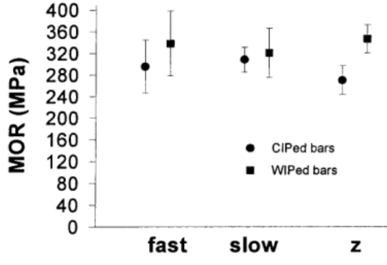
CIP vs. W IP ... 54
Contamination defects vs. 3DP-induced intragranular pores... 55
Microstructural Analysis... 59
A control experiment in compaction... 59
Linear raster bars vs. staggered and checker bars.. 61
4.1.2 G reen B ars... 63
Mechanical Characterization... 63
MOR standardization calculations... 63
MOR as a function of loading direction... 66
-- anisotropic internal defects Effects ofprinting parameters/style on MOR... 68
MOR as afunction of surface characteristics... 68
Microstructural Analysis... 70
Lines-Isolated single, double, and quadruple... 70
line sequences, and lines in multilayered parts SEMfractographs of green bars... 75
Polished cross sections of partially sintered bars... 76
4.1.3 Isopressing Shrinkage Measurements... 80
F ine Pow der... 80
4.2 Alumina Prechambers... 82
4.3 Silicon N itride P arts... 83
5 C O N C L U SIO N S ... 85
REFERENCES ... ... 88
LIST OF FIGURES
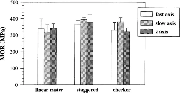
Figure 2.1: Figure 3.1: Figure 3.2: Figure 3.3: Figure 3.4: Figure 3.5: Figure 4.1: Figure 4.2: Figure 4.3: Figure 4.4: Figure 4.5: Figure 4.6: Figure 4.7: Figure 4.8: Figure 4.9: Figure 4.10: Figure 4.11: Figure 4.12: Figure Figure 4.13: 4.14: Figure 4.15:Schematic diagram showing the fast, slow, and z axes on a three-dim ensional printer... Lines are stacked on top of each other in the linear raster print sty le ... Line spacing is increased and layer thickness reduced in the staggered style... Schematic showing the formation of consecutive lines and layers using the checker build style ... The two directions along which fast, slow, z bars were loaded... The six different tensile stress configurations along which the extent of stitching was measured... MOR values for fired linear raster bars that were CIPed or W IPed prior to firing... Mean fired strength vs. print style... Mean fired strength vs. loading direction ... Optical micrograph of a metal contaminant particle on an alum ina bar surface... Fractograph of fired linear raster z bar showing intragranular pores betw een lines... Fractograph of fired linear raster slow bar, showing a ~320 pm lamination defect... The same defect in Fig. 4.6 at the top left-hand corner & another defect parallel to it 270 im (- 2 layers) below... Fired linear raster bar cross section showing lamination defects... Fired staggered bar cross section. No lamination defects are p resen t... Fired linear raster bar cross section showing defects
betw een lines... Fired staggered bar cross section. 3DP-related defects are ab sen t... Fired linear raster bar cross section showing large pores betw een layers... Fired staggered bar cross section. Porosity is much finer... Standardized green MORs vs. print style. The numbers 1-6 represent the different loading directions... Standardized green MORs vs. print style. Average MOR ratios along the fast, slow, and z axes are given for the three p rin t sty les...
-Figure 4.16: Figure 4.17: Figure 4.18: Figure 4.19: Figure 4.20: Figure 4.21: Figure Figure Figure Figure 4.22: 4.23: 4.24: 4.25: Figure 4.26: Figure 4.27: Figure 4.28: Figure 4.29: Figure 4.30: Figure 4.31: Figure 4.32: Figure 4.33: Figure 4.34:
Standardized green MORs vs. loading direction... Stereomicrograph of an isolated single line sequence of acrysol printed on spray dried alumina powder... Schematic of the steps in the formation of adjacent lines on spray dried alum ina... Stereomicrograph of an isolated double line sequence of acrysol printed on spray dried alumina powder... Stereomicrograph of an isolated quadruple line sequence of acrysol printed on spray dried alumina powder... The top surface of a WIPed fast linear raster showing
m issing and m erged lines... Fractograph of linear raster green slow bar showing layers... Fractograph of linear raster green fast bar... Fractograph of linear raster green z bar, showing lines... Optical micrograph of a green linear raster fast bar showing defects between consecutive layers... Optical micrograph of a green staggered fast bar showing no d efects... Optical micrograph showing defects between pairs of lines in the green linear raster fast-slow plane... Optical micrograph showing that no defects exist
in the green staggered fast-slow plane... Optical micrograph of the green linear raster z-slow
plane reveals no clear patterns... Optical micrograph of the green staggered z-slow plane reveals two parallel diagonal pullout lines--an effect of the staggered p rin t sty le ... Average % shrinkage upon WIP for different powder systems
and print styles along the fast, slow, and z directions... Left to right: as printed, CIPed, and CIPed & fired alumina prech am bers...
Same prechamber parts as Figure 4.32 as seen from a different angle... Fractograph of Si3N4part showing elongated p-Si3N4 grains...
LIST OF TABLES
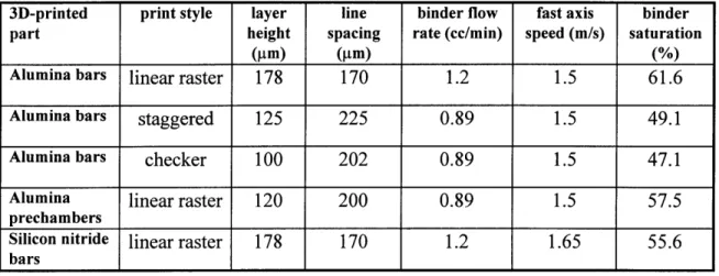
Table 2.1 Demonstrated mechanical properties of 3DP-derived materials... 36 Table 3.1 The printing parameters used in making the parts referred to
in this th esis... 4 8 Table 4.1 Comparison of the three print styles with respect to the intergranular
porosity, granular bulk density, and radii of the spray-dried granules that were used for each printing run and the radii of the binder necks
CHAPTER 1
INTRODUCTION
Three-dimensional printing is expected to produce parts with anisotropic characteristics by virtue of the additive nature of the process. The knitting between primitive elements will be different along different directions, leading to strength and shrinkage anisotropy. The incentive to study the effects of print style on strength anisotropy has originated from studies done on investment casting molds. A modification of the simple raster scan print style was found to lead to much improved green strengths and to prevent breakage of molds during metal casting [Charnnarong]. Another modification to the print style, namely the implementation of triangular deflection of droplets (described under print styles in section 3.2.1) was observed to prevent splits during debind and sinter of metal parts, presumably by improving stitching along the slow axis. These two findings provided the motivation for verifying the existence of similar effects in the case of structural ceramics. The spray dried alumina-acrysol system was chosen for the current study.
The purpose of this thesis was to first determine the extent of green and fired strength anisotropy in structural ceramics parts fabricated via 3DP. To this end, the green and fired strength of long rectangular bars oriented along the three orthogonal axes of the 3D printer, i.e. the fast, slow, and z axes, were determined by four-point bend testing.
These results, along with shrinkage measurements revealed that green strength anisotropy was indeed an issue for current system. The goal was then to investigate the effects of varying a number of printing parameters, known collectively as the "print style," on the mechanical and microstructural properties of both green and fired parts. These parameters include the layer height, the line spacing, line arrangement, binder flow rate, and proportional deflection. This study was done in an effort to determine the potential benefits of print style modification as a means to the end of reducing the size and number of defects arising during the 3DP step. The simple linear raster scan style is compared with two different print styles, namely the staggered and the checker styles. Microstructural examination and four-point bend testing of green and fired bars prove that print style does have an effect on microstructure and strength.
In addition to the results of print style related experiments, this thesis reports mechanical strength data for 3DP-derived structural ceramics parts (Table 2.1) and describes how the current Cold Isostatic Pressing (CIP) technique was modified to allow CIP of complex shapes with hollow interiors (sections 3.3.2 and 4.2).
CHAPTER 2
BACKGROUND
2.1 Advanced Structural Ceramics
Ceramics are broadly classified as functional or structural depending on the type of application for which they are used. The former are used in applications that exploit their optical, electrical, and magnetic properties. Structural ceramics are used in applications that require excellent thermal and mechanical properties. They are expected to perform mechanical functions that demand high mechanical integrity at elevated temperatures. High strength-to-weight ratio, wear resistance, corrosion resistance, and high thermal shock resistance are among the major requirements. The most important examples of structural ceramics are materials that are based on alumina, zirconia, silicon nitride, and silicon carbide.
Nearly all experiments for this thesis have been performed using A1203. This
ceramic material is used in a wide variety of materials-processing technology applications (textile guides, nozzle inserts, cutting tools, milling media) and electrical applications (spark plug insulators, electronic substrates, electrical insulation).
2.2 Processing of Advanced Structural Ceramics
Classical ceramics are processed from natural raw materials. Advanced structural ceramics, on the other hand, are manufactured from chemically processed materials.
Alternative manufacturing methods such as sol-gel processing, direct melt oxidation, and impregnation of fiber structures are currently being explored. However, advanced ceramics have traditionally been produced through the classic powder processing methods described below.
2.2.1 Powder Synthesis
The starting powders must be pure in terms of foreign particles for a structural ceramic component to have the desired reliability and high strength. They should also be free of hard agglomerates. Hard agglomerates are known to result in defects, and thus reduce the strength of the final product. The starting powder particles should be uniform, roughly spherical, and of a fine size, typically submicron, in order for a uniform, fine-grained final microstructure to be achieved. Alumina powder for structural ceramics is manufactured through one of four processes: the Bayer process, thermal decomposition of ammonium-alum, hydrolysis of aluminum alkoxides, and treatment of aluminum flakes by electric power discharge in water (Iwatani process) [Gauckler, 1988]. These processes are capable of yielding powders of varying fineness, and Na2O impurity levels. The
Reynolds RC172-DBM used for in our study was MgO doped A1203 synthesized by the
Bayer process. MgO is commonly added to A1203 as a grain growth inhibitor.
2.2.2 Powder Processing
The powder must be prepared for the subsequent forming method once it has been synthesized. A polymer-ceramic mixture of high (up to 30 vol%) polymer content is
prepared for plastic-forming methods such as extrusion and injection molding. Fine ceramic powder is dispersed in a liquid vehicle, either water or an organic solvent in slip casting and tape casting. Small amounts of organic stabilizers (or deflocculants) are added to prevent the formation of particle aggregates which can lead to structural faults in the final product. Appropriate amounts of binder and plasticizer (- 6 vol% of each) are added also in the case of tape casting. The most widely used forming process is dry pressing. This process works best with highly flowable, controlled granules. Such granules are often prepared by spray-drying. A small amount of binder is added to the slurry to be spray dried. The binder serves the purpose of holding together the ceramic particles that make up individual spray-dried granules, and of improving the compaction behaviour of granules. A plasticizer is commonly added to ease deformation of granules during the subsequent pressing stage. The spray-dried alumina powders used in our experiments were produced in-house.
2.2.3 Forming Methods
Several forming methods exist for consolidating ceramic feed material into a coherent body having a definite shape and microstructure. The goal of all forming methods is to produce a homogeneous green body with high green density. The green body is generally required to be about 60% of theoretical density for ceramics that sinter by solid-state diffusion. Green densities as low as 30% would have been sufficient to ensure normal sintering at the sintering temperature (= 1650'C) used in the present work. Green densities lower than about 30% would fall into the subnormal regime [Bruch,
1962] where sintering does not occur. These issues will be discussed further in section 2.2.5. Some of the conventional forming methods are briefly described below. The uniqueness of 3DP as a viable forming method will be described in section 2.7.2.
Injection Molding/Extrusion
Injection molding is a plastic forming technique whereby a ceramic-polymer mixture is injected into a mold by a plunger, using a combination of heat and pressure. The viscosity of the plastically deformable mixture is required to be low for proper filling of the mold and for prevention of air bubble entrapment. Extrusion, a similar plastic-forming process, is used to produce long, uniform cross section parts. Extrusion dies are open at one end in contrast to injection molding dies. Clay bricks, tiles, and pipes, as well as monolithic cordierite honeycomb structures for catalyst supports have been fabricated by extrusion.
Slip Casting
Slip casting involves pouring a ceramic slip into a porous mold, commonly a gypsum mold with 40-50% porosity, which absorbs liquid and deposits solid material on the mold walls. Excess slip is drained off. The cast is then removed and fired. The quality of a cast generally depends on three factors. First, the slip must be stable so that deposition occurs evenly on the mold walls. Second, the solids content must be high (-70 wt%) to improve drainage rate. Lastly, as with injection molding, slip viscosity must be low enough so that the mold may be filled easily, and air bubble incorporation
into the green body prevented. Slip casting has been used for manufacture of tableware, sanitaryware, crucibles, tubes, thermocouple sheaths, and gas turbine stators.
Dry/Isostatic Pressing
Pressing is used for the simultaneous compaction and shaping of soft, controlled agglomerates in a rigid die (dry-pressing), or a flexible mold (isostatic pressing). Parts thicker than 0.5 mm and parts with surface relief in the pressing direction are dry-pressed
using hardened metal punches. Products fabricated by dry-pressing include various fine-grained technical aluminas such as spark plugs, engineering ceramics such as cutting tools, ceramic tile and porcelain products, coarse-grained refractories, grinding wheels, and structural clay products.
Pressure, and consequently density gradients are set up within a compact during dry-pressing due to die wall friction. Isostatic pressing, or isopressing, offers one way of reducing this friction effect, thus minimizing density gradients within the green body. Isopressing involves pressurizing powder filled flexible rubber molds in liquid pressure chambers. This method is used to produce shapes with relief in two or three directions. A variation of the so-called wet bag technique, which is commonly practised in industry for pressing complex shapes of various sizes and large refractories, was used for our specimens.
Nonuniform density, nonparallel faces, and breakage become important limiting factors in dry-pressing of articles that are thinner than 2 mm. Tape casting, a continuous, high-productivity process, is the viable alternative for the manufacture of flat, smooth, thin (0.01-1 mm) ceramic substrates of uniform density. A film of controlled thickness is formed when a slurry flows down an inclined substrate, or under a blade onto a supporting surface. The cast film is dried to an elastic, leathery state, and cut to the proper handling width. A puncher is used to shape the dried film. This process is used to manufacture substrates for multilayer ceramic electronic packaging, multilayer titanate capacitors, piezoelectric devices, thick and thin film insulators, ferrite memories, and catalyst supports.
2.2.4 Compaction Behaviour of Spray Dried Granules
Plotting relative green density vs. log (punch pressure) for spray-dried granule compacts reveals that compaction of spray-dried granules occurs in three distinct stages [Youshaw, 1982]. In stage I, granules might rearrange some to give a higher than fill density packing. Stage II typically begins at about 1 MPa. During this stage, depending on the amount and plasticity of the binder, granules fracture or deform, filling up intergranular voids. Of the three stages, the highest extent of densification occurs in this stage. Large intergranular pores, as well as interfaces between softer granules are mostly eliminated. Interstices between harder granules persist into stage III, which starts at about 20 MPa. During stage III, particles rearrange a bit further into a denser packing configuration, increasing the homogeneity of the powder mass.
Intergranular pores have a negative effect on the densification of green compacts during sintering and on the bending strength distributions of the sintered bodies. These pores must collapse completely to produce highly reliable, high-strength ceramics. This is discussed in further detail in the following section.
2.2.5 Sintering-- Pore Elimination
Sintering refers broadly to the changes in grain/pore size and shape that ceramic (or metal) particles in contact undergo when heated to high temperatures. The elimination, or at least minimization of porosity by the sintering process is essential in ceramics if properties such as strength [Carniglia, 1972; Davidge and Evans, 1970], translucency [Peelen and Metselaar, 1974], and thermal conductivity are to be maximized. Experimental data suggests that strength, for instance, is decreased nearly exponentially with porosity. This is because residual pores in a fired part increase the amount of stress experienced by that part. They do so not only by reducing the effective load bearing cross sectional area, but also by acting as local stress concentrators. The stress is increased by a factor of two in the vicinity of an isolated spherical pore.
Densification, or consolidation of a porous green compact to full density by pore shrinkage, is accomplished by solid phase or liquid phase sintering. The driving force for sintering is the decrease in total free energy of the system associated with replacement of solid-vapor interfaces by lower-surface-energy solid-solid interfaces, namely grain boundaries [Smith, 1948; Coble, 1959]. This is achieved by the transport of material away from the contact area between two particles into the necks around this area.
Regardless of whether this occurs by bulk diffusion, grain boundary diffusion, or through a liquid phase concentrated at the grain boundaries, the transport distance will be smaller, and the sintering rate will thus be higher for smaller grain sizes.
Stages of Sintering
Sintering can be conceived as a three-stage process [Coble, 1961 (I)]. The initial
stage is where necks form at the contact points between particles. This is accompanied
by interparticle shrinkage of a few percent [Kingery and Berg, 1955; Coble, 1958]; the relative density of a typical powder compact will increase by about 20% during neck growth. No grain growth occurs, i.e. the boundaries between the single-crystal particles do not migrate during the initial stage. This is because the solid-vapor surfaces diverge from the grain boundary surfaces at an acute angle. Migration of the boundary would result in a significant increase in grain boundary area given this particular geometry and thus be energetically unfavorable. The termination of the initial stage is marked by the onset of grain boundary migration, i.e. grain growth, as the transport of matter to the necks rounds and blunts them, relieving the geometrical restraint.
A significant amount of grain growth and pore shape change takes place before
the intermediate stage begins, forming equilibrium dihedral angles at the pore-grain
boundary intersections. The intermediate stage itself is characterized by a shrinking continuous, interconnected pore phase, intersected by grain boundaries.
The final stage begins as the continuous pore phase breaks up into isolated pores
stable fashion hereafter. However, discontinuous, (a.s.a abnormal, or exaggerated) grain growth may occur, leading to the entrapment of porosity inside grain interior. During discontinuous grain growth, grain boundaries move on across pores and reform on the other side. Pores entrapped thus will generally persist to high density since they must rely on lattice diffusion for closing off, which is a relatively slow transport mechanism. Densification can only proceed at a reasonable rate if the sources and sinks for the associated diffusion process are kept close together. The pores must remain attached to or at least close to grain boundaries if full density is to be attained [Burke, 1957; Burke and Rosolowski, 1974]. Thus, discontinuous grain growth must be actively suppressed during the final stage of sintering for the attainment of close to theoretical density [Coble and Burke, 1963]. This is achieved by the addition of grain growth inhibitors. In the case of A1203, for example, MgO is used for this purpose [Coble, 1961 (II)].
Porosity is never ideally distributed in experimental green samples. As a consequence, a distribution of pore sizes will generally exist as the intermediate stage of sintering is entered. The pore concentration variations will generally persist to the final stages of sintering as a result of the slower elimination of larger pores. Large pores in a poorly compacted powder tend to be thermodynamically stable or even grow [Rhines, 1950]. A ratio of pore diameter to grain diameter greater than 1.5 is sufficient for pores to grow in pure alumina [Kingery et al, 1976]. Carbone and Reed (1978) have also found that a broad range of pore sizes distributed inhomogeneously leads to poor sintering behaviour. They report that a uniform distribution of pores up to about one particle size is required for optimum sintering characteristics.
Subnormal/Normal Sintering Regimes
The relationship between green and final density in the MgO-doped alumina system has been studied extensively [Bruch, 1962; Greskovich, 1972]. Bruch defines two sintering regimes based on the variation of the time exponent with temperature and green density in an empirically derived sintering kinetics equation. The region in the green density-temperature space where the time exponent is independent of these two parameters is called the normal sintering regime. This behaviour is observed at higher green densities and/or higher temperatures. The magnitude of the time exponent decreases with decreasing green density and/or temperature in the so-called subnormal
sintering regime. An important observation made by Bruch is that for compacts within
the normal sintering regime, green density has a profound effect on the rate coefficient, viz. the coefficient increases with green density. Thus, lower density compacts can "catch up"with higher density compacts, i.e. achieve approximately the same final density within a given period as higher density compacts.
The consequences of having higher and lower density regions within a uniform packing density green matrix were studied by Lange and Metcalf (1983). They observed that for specimens containing lower-density agglomerates, circumferential cracklike voids were formed at the agglomerate/matrix interface. Similar results were obtained for our specimens. Uncollapsed spray-dried granules have a lower green density (- 50% theoretical density) than the surrounding collapsed powder mass (~ 60% theoretical). The range of sintering variables in the present work (local green density = 50-60%, sintering
temperature = 1650'C) were such that sintering occurred strictly in the normal regime as defined by Bruch (1962). Thus, the lower-density uncollapsed or partially collapsed granules presumably sintered at a faster rate than the surrounding matrix, attaining approximately the same final density. Due to the differential shrinkage, intergranular pores were exaggerated. These results are discussed further in section 4.1 .1.
2.3 Fracture Strength of Structural Ceramics
No metal can be used under mechanical load at temperatures above 1100*C without the use of some sort of cooling system [Gauckler, 1988]-- for such applications, advanced structural ceramics stand alone as the materials of choice. Ceramics have great thermal and chemical stability, high hardness and wear resistance owing to their strong ionic and covalent interatomic bonds. However, these bond characteristics preclude the plastic behaviour that is normally associated with metals, causing them to undergo brittle fracture.
Crack initiation is the critical stage of the rupture process in brittle materials like ceramics. The crack begins to propagate under the right stress conditions once it is initiated since there is no large energy absorbing process like in ductile materials. Grain boundaries in polycrystalline ceramics can act as obstacles that force the crack to change direction at a boundary, increasing fracture stress by a factor of 2 to 4.
The part fails when the crack finally grows above a certain critical size. Crack propagation occurs when the decrease in stored elastic energy associated with the extension of the crack exceeds the energy required to form the new fracture surfaces.
This energy balance argument first formulated by Griffith leads to the following equation for fracture strength:
K (2.1)
(rc),
where a F = fracture stress
K= fracture toughness
c = crack size
Equation 2.1 clearly suggests that there are two possible ways of increasing the strength and reliability of structural ceramic components. The first of these is to reduce the size of (both process and machining-induced) defects, which act as stress concentrators and lead to breakage at relatively low stresses. The second approach is to increase the fracture toughness of the material through techniques such as transformation toughening (e.g. A1203-ZrO2), the introduction of a second phase (e.g. SiC-TiB2), fiber and whisker reinforcement (e.g. A1203-SiC), or grain boundary engineering (e.g.
Si3N4/YAG) [Gauckler, 1988]. The present work focuses on eliminating or at least
reducing the number and size of processing related defects, specifically those introduced during the three-dimensional printing step (see section 2.5.4 and 2.6 about 3DP).
2.4 Mechanical Testing of Structural Ceramics
---The maximum tensile strength of ceramics is ordinarily not determined through tensile testing due to the inherent difficulty in gripping brittle specimens without breaking them. Instead, three-point and four-point bend testing are widely used. The maximum tensile stress that the specimen can withstand, namely its Modulus of Rupture (MOR) is largely determined by the size of flaws present in the stressed region of the specimen, which act as stress concentrators. The entire volume of the specimen is under maximum stress in the case of tensile testing. The maximum stress is restricted to a line on the surface of the specimen in three-point bending, and a planar region in four-point bending [Nunomura, 1989]. Consequently, for the same specimen shape and size, the probability of finding a supercritical flaw in the stressed region is highest in tensile testing, lower in four-point bending, and lower still in three-point bending. The mean value and variability in strength in bend testing is correspondingly higher compared to tensile testing.
2.5 Solid Freeform Fabrication (SFF)
Solid Freeform Fabrication, otherwise known as rapid prototyping or desktop manufacturing, can be defined as the production of freeform solid objects directly from a computer-aided drawing (CAD) without the use of part-specific hard tooling, dies, or molds. A variety of SFF techniques have been developed in recent years that use radically different techniques and materials. The common aspect of these systems is that they construct parts or prototypes through additive laminated building processes. A three-dimensional representation of the part is sliced into two-dimensional cross sectional layers. These slices are then used to guide the SFF machine in building the part on a
layer-by-layer basis. Presented below is a brief description of those SFF techniques that have been demonstrated in the manufacture of structural ceramics.
2.5.1 Laminated Object Manufacturing (LOM)
Laminated Object Manufacturing [Griffin, 1994] is capable of building parts out of paper, plastic, metal sheet stock, or ceramic tape. A sheet of material is rolled in over the work area. A computer-guided laser cuts out a cross section of the part and cuts the remaining portions into tiles to facilitate part removal. A new sheet is laminated to the previous sheet by passing a hot roller to activate a previously applied adhesive layer. This process is repeated until the full part emerges.
2.5.2 Selective Laser Sintering (SLS)
Selective Laser Sintering is commercially available for use with polycarbonate, PVC, and wax powders. Parts have been fabricated from metal and ceramic powders also. SLS is based on spreading uniform layers of powder material much like three-dimensional printing (3DP). A CO2 laser then scans the powder bed in
computer-specified regions. The beam intensity of a laser can be adjusted so as to melt or sinter together the powder material. This spreading-scanning cycle is repeated until the part is completed.
Direct sintering of ceramic materials with SLS requires the use of high laser energies (~1000 cal/cm2). However, even at these high intensities, completed parts hardly hold together because of the high thermal gradient and rapid heat dissipation
involved. Low melting temperature inorganic and organic second phases have been used to obtain green alumina parts [Subramanian et al, 1994].
2.5.3 Stereolithography
Stereolithography has traditionally been used to make plastic parts. A UV laser scans a bath of acrylate liquid causing it to photopolymerize in selected regions. The cured part is supported usually from underneath by a flat surface attached to an elevator which lowers once the layer is completed. The liquid polymer flows over the cured part, and the laser scans the next cross-section. Attempts have been made at adapting Stereolithography to produce ceramics. Alumina slips consisting of 45-55 vol% ceramic powder have been dispersed within a UV-curable aqueous acrylamide solution [Griffith, 1994]. Single layer parts have been constructed using this new technique.
2.5.4 Three Dimensional Printing (3DP)
3DP is a solid freeform fabrication technique that utilizes ink jets to place binder droplets in a computer-specified pattern onto layers of powder material. The ability of 3DP to fabricate parts out of materials as diverse as polymers [Borland], metals [Michaels, 1992], ceramics [Yoo, 1993], glass, and glass-ceramics [Nammour, 1995] has been demonstrated.
A pile of powder is dispensed at the edge of the piston which supports the powder bed. A spreader rod then pushes the powder across the piston, spreading it in a thin layer
Most powders (e.g. 30 micron alumina and metal powders) are dispensed automatically from a reservoir situated above the machine. Powder layer generation techniques have been described elsewhere [Lee, 1992].
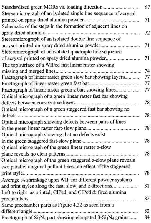
Once the spreading of the powder layer has been completed, it is raster scanned by the printhead. Liquid binder is delivered through a continuous-jet type ink-jet printhead. The continuous stream of binder that passes through a nozzle with a 45 pm orifice is made to break up into small droplets by a piezoelectric disc attached to the nozzle vibrating at about 60 Hz. Droplets are then selectively charged as they pass through a capacitor. A high voltage electric field deflects the charged droplets, directing them onto a "catcher" so that the unprinted binder may be recycled. Uncharged droplets pass undeflected through the deflection cell, falling vertically into the powder bed. Thus, the powder bed gets selectively glued together by the binder droplets. The spreading-printing sequence is repeated until the full green part emerges. Figure 2.1 shows the so-called fast, slow, and z axes on a three-dimensional printer.
X-Axis (slow) Y-xst) Printhead Z-Axis (v. slow) Powder Bed
Figure 2.1 Schematic diagram showing the fast, slow, and z axes on a three-dimensional printer.
2.6 Process Physics of Three-dimensional Printing (3DP)
2.6.1 Single Drop Primitives
The smallest building block in a 3D-printed part is called a primitive, and is an agglomerate of powder particles (or granules) formed by a single binder droplet. Powder particles are pulled together into spherical agglomerates in response to the binder liquid surface tension forces. The physics of primitive formation has been studied extensively [Bredt, 1995]. The single drop primitive size is determined by various factors such as binder drop chemical composition and size, powder chemical composition and size, layer thickness, powder bed density and surface tension. For example, a 75 ptm drop of colloidal silica printed on a 175 pm thickness of 30 pm alumina powder will form a 125 ptm drop primitive.
Drying of the binder droplet will typically be accompanied by rearrangement of the powder particles leading to further densification. Indeed, the packing density of primitives composed of 325 mesh alumina powder is 1.8 times higher than the rest of the powder bed [Lauder, 1992]. Thus, the primitive represents a defect since its formation results in an inhomogeneity in the packing density of the powder. The spray dried granules used in this study are certainly prone to rearrangement upon contact with the liquid binder since they have high flowability, i.e. low cohesive strength.
The simplest print design places binder droplets on a straight line to form the next substructure in the hierarchy, the printed line. The 75 pm droplets in the example above, when overlaid on each other every 20 pm, will form a 200 pm wide line [Sachs, 1994]. This highly linear arrangement ensures good knitting between primitives within a printed line along the fast axis. However, this occurs at the expense of poor knitting along the slow axis. Defects appear between pairs of lines as a result of the ballistic interaction between the powder and the binder combined with powder rearrangement effects [Lauder, 1992]. "Triangular deflection" is currently being used to help alleviate this problem. This print pattern is described in greater detail in section 3.2.1. The specific observations pertaining to line formation in spray dried powder beds are given at the end of section 4.1.2.
2.6.3 Layers
Knitting between individual layers can be improved either by reducing the layer thickness, and/or by modifying the print style. Cylindrical printed lines are stacked right on top of each other in the simple linear raster print style. An alternative approach (staggered style) reduces the layer thickness and staggers the lines so as to achieve a more closely packed line arrangement. This approach was first demonstrated to reduce strength anisotropy in bars printed with coarse alumina powder and silica binder [Chamnarong]. The present work corroborates this effect for the spray dried alumina -acrysol system.
There are other important printing parameters besides print style and layer thickness, such as binder saturation in the powder bed (controlled by the printhead speed
along the fast axis, the binder flow rate, the powder bed packing density, line spacing, and layer thickness), as well as materials parameters, such as the wetting characteristics of the powder. These also play an important role in determining the defect structure and mechanical strength by affecting how the printed lines rearrange themselves and how the binder gets distributed within the printed part.
This thesis discusses the extent of anisotropy found in green as well as fired structural ceramics printed using three different print styles. The effect of print style alone on strength anisotropy and microstructural properties was demonstrated by varying the print style while keeping other parameters constant (or by factoring out the effects of other parameters).
2.7 Strength and Anisotropy in Structural Ceramics via Conventional vs. SFF Techniques
2.7.1 Conventional Methods
The values reported for room temperature bending strengths of polycrystalline 98% bulk density alumina vary as a function of porosity in the range from 200 to 500 MPa depending on experimental conditions and material composition.
Another source lists strengths for different grain sizes [Cook, 1985]. The average strength for alumina with a 3 im grain size is 488 MPa; for 11 pm, 400 MPa; and for 25 ptm, 302 MPa. The grain size in our samples is -4-7 tm, which corresponds to -450 MPa.
---A commercial grade alumina is reported to have bending strengths of 379 MPa. (Data from product data sheet for AD995 (99.5%) alumina, data sheet 7164C FP 20K 2/89, Coors Ceramics Co.)
2.7.2 Solid Freeform Fabrication Techniques
The only solid freeform fabrication (SFF) technologies that have demonstrated structural ceramic parts are LOM, Stereolithography, SLS, and 3DP.
LOM
Strength results for dry-pressed and LOMed bars have been compared [Griffith, 1994]. Flexural strength varied ~ 3% with direction in dry-pressed bars (w/ 0.4% open porosity). Bars where the tensile stress was applied parallel to the pressing direction broke at -336 MPa. Average strength was 325 MPa for stresses applied perpendicular to the pressing direction.
Flexural strengths of about 310 MPa were reported for LOMed alumina bars with 1.0% open porosity. Strength anisotropy in this case was statistically insignificant. The test direction parallel to the lamination direction produced an average of 314 MPa; the perpendicular test direction produced 311 MPa.
Stereolithography
Ceramic green bodies have recently been created through Stereolithography of dispersions of alumina slip (45-55 vol% solids) within a UV-curable aqueous acrylamide
solution. Only one layer thick green parts (300 pm) have been built so far. However, initial results are promising.
SLS
Fully dense monolithic structural ceramics have not been demonstrated for this technique. However, SLS was done on 100 ptm agglomerates of 2 pim A1203 particles
mixed with polymer powder to construct alumina green samples [Subramanian, 1994]. Samples were built in different orientations. The green bend strengths revealed that samples built using shorter scan lines have higher strengths (- 2 MPa). The anisotropy is due to the fact that, for shorter scan lines, there is less time for heat dissipation between two consecutive scans. The process physics is quite different than both LOM and 3DP. However, in both SLS and 3DP, anisotropy is a result of the additive nature of solid freeform fabrication.
3DP
3DP has two main advantages over conventional powder forming methods. Fabrication of complex shapes through powder molding processes like injection molding involves forming a heavily plasticized powder mass against a mold. Depending on the shape and size of the mold, differential shear forces may develop during the process, resulting in inhomogeneity in powder packing, which in turn leads to distortion upon firing. In contrast, each layer in the 3DP process is prepared in the same way so that the particular shape or size of a part has no effect on distortion. Secondly, a 3D-printed
ceramic green body typically contains 2-3 wt% binder unlike injection molding, where up to 30 v/o polymer is required to plasticize the powder. Thus, 3DP is potentially unrestricted in its capability to manufacture parts having large dimensions unlike injection molding where cracking problems during binder burnout preclude manufacture of thick cross section parts.
The capability of 3DP to fabricate structural ceramic components has been demonstrated for several different materials systems. Prior to this study, a number of structural ceramic parts had already been fabricated out of fine alumina powder using the press-rolling spreading sequence and the linear raster print style. Bars constructed this way had average MORs of 324 MPa [Yoo, 1993].
Spray dried alumina powders were used for the current study. Fabrication of alumina bars involved three different print styles. The highest fired MORs (~400 MPa) were obtained using the so-called staggered style. Green strengths along different directions varied by a factor of 3. On the other hand, virtually no strength anisotropy was observed in fired bars.
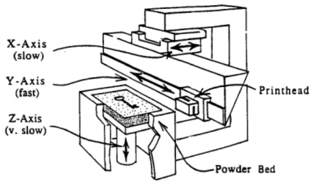
Silicon nitride bars with flexural strengths of 570 ± 112 MPa were also fabricated. Concurrently, Zirconia Toughened Alumina (ZTA) bars with an average strength of 475 MPa were constructed by Yoo (1995). Flexural strengths of inceram infiltrated alumina parts prepared by Nammour averaged 205 MPa. These flexural strength results are summarized below in Table 2.1.
Table 2.1 Demonstrated mechanical properties of 3DP-derived materials.
Finally, a wet deposition process is currently being developed by Khanuja for direct fabrication of structural ceramics. The process features spray deposition of slurries, building high green bodies that can be sintered directly to full density. It eliminates the need for the intermediate isostatic pressing step required in dry processing.
Type of Material 4-pt Bend Strength (MPa) Inceram infiltrated 205 A1203 [Nammour, 1995] fine A1203 Yoo, 1993] 324 linear raster A1203 340 checker A120 3 340 staggered Al203 380 ZTA Yoo, 1995] 475 Si3N4 570 ANOWINNOMM
CHAPTER 3
EXPERIMENTAL PROCEDURE
3.1 Materials
The ceramic powder used in almost all of the experiments reported in this thesis was spray dried A1203. The mechanical strengths of parts made out of Si3N4 are included
as well. The binder used was a diluted form of Acrysol WS-24 in all cases.
3.1.1 Binder
The binder used in all the experiments was a 6 vol% Acrysol WS-24 (Rohm and Haas Company, Philadelphia, PA) solution in water (99.9 vol% water, 0.1 vol% ammonia). Acrysol is an acrylic copolymer dispersion resin.
This formulation, originally optimized for submicron alumina powder [Yoo, 1993], was adopted successfully for all the spray-dried as well as the submicron powders used in this study.
3.1.2. Powder
Alumina
Spray dried alumina powder was prepared from submicron alumina powder (Reynolds RC 172 DBM) using an in-house laboratory scale spray drier. 2 wt%
polyacrylic acid (M, = 240,000) was used as a binder. The resulting spherical spray dried granules had high flowability and a packing density of ~ 30% on spreading. Bulk density of granules varied from batch to batch, averaging about 47%. Fines, i.e. loose submicron particles, were sieved out in most cases. Granule sizes between 30 pm and 100 pm were used for printing.
Silicon Nitride
Si3N4 powder (grade M 11; H.C. Starck, Germany), containing 6wt% Y203 (Atlantic Equipment Engineers; Bergenfield, NJ) and 6wt% A1203 (Baikalox type CR-30;
Baikowski International Corporation, Charlotte, NC) as sintering additives was used to fabricate rectangular bars. The powder mixture was ball milled for 20 h in ethanol using ZrO2 media. The slurry was air dried, crushed, and sieved to obtain agglomerates
between 53 pm and 106 pm for printing. Spray-drying was not used in this case.
3.2 Sample Preparation- 3D Printing
3.2.1 Alumina Bars and Lines
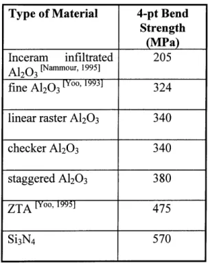
Three sets of rectangular bars (0.46x0.46x3.8 cm) were fabricated on the alpha-machine using three different print styles, namely the linear raster, staggered, and checker styles. Figures 3.1-3.3 show the distinctive features of these print styles. Each set of bars consisted of fast, slow, and z bars, with their long axes parallel to the three orthogonal axes of the 3D-printer (Figure 3.4). Four-point bend testing was performed on
fasi
Z
slow
178 pm
170 pm
Figure 3.1 Lines are stacked right on top of each other in the linear raster print style. The dimensions that were used are indicated in this drawing.
Z
fast
slow
125 ptm
225
tm
Figure 3.2 Line spacing is increased and layer thickness reduced in the staggered style. Lines are staggered in alternate layers to achieve higher packing.
8
8
I
II
I
a) A singleline8
5c
b) Two consecutive lines 250 microns apart
I
I
II III
II III
V....
I
8
8
12
178
3
c) Three consecutive lines
d)Two consecutive layers
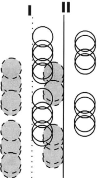
Figure 3.3 This schematic shows consecutive lines and layers in the checker build style. The total deflection for a given line is 250 microns. Line spacing is 125 microns.
I, II, III represent the centerlines ofthe 1st, 2nd, and 3rd lines in the 1st layer 1,2, and 3 represent the 1st, 2nd, and 3rd lines in the subsequent layer
The empty circles are the primitives of the last line to be printed.
( a / '4% / %' -. 1 a ~, a / a / \ -~1
Z axis
Fast axis
Slow axis
23
3
4
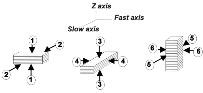
Figure 3.4 Fast, slow, z bars were all loaded in one of two directions
z
I
fast
Sl|W
Figure 3.5 The extent of stitching in 3D-printed green parts was measured along two different axes in three different planes, creating six difenmttensile stress configurations The numbers correspond to the six loading directions shown in Figure 3.4
as-printed green bars in order to understand the effects of print style on the quality of stitching between primitives in different planes and along different directions. Each type of green bar was loaded in two different ways, creating a total of six distinct tensile loading configurations as shown in Figure 3.5. Such a distinction was not made in the case of fired bars. Fast and slow bars were always broken with the top surface (last layer to be printed) in tension while z bars were always broken with the front surface (formed by the last line in each layer) in tension.
Strategy
6 vol% Acrysol had already been established as the optimum binder formulation for printing on fine alumina powder [Yoo, 1993]. Higher concentrations (12 vol%) were found to lead to binder build-up between layers, forming interlaminar defects [Yoo, 1993]. The linear raster bars were thus fabricated by printing 6 vol% Acrysol. The other printing parameters that were used are tabulated in Table 3.1 in Section 3.2.3. The saturation values in this table assume the intragranular porosity within spray dried granules to be completely accessible by the binder solution.
The fracture surfaces of linear raster bars that were isopressed (240 MPa, 80'C) and then fired revealed long linear defects that were clearly formed during the 3DP step. That these defects were 3DP-induced was confirmed by a compaction experiment where loose spray dried alumina powder was post-processed and fired in the same exact way as the printed bars, i.e. evacuated, WIPed, and fired according to the recipes given in Section 3.3.1. The thickness of the loose powder was made to approximate the thickness of the