Dinitrogen Fixation Chemistry of a Molybdenum Trisanilide System
byJohn Joseph Curley
B. Sc. Chemistry University of Chicago2004
Submitted to the Department of Chemistry in Partial Fulfillment of the Requirements
for the Degree of
DOCTOR OF PHILOSOPHY at the
MASSACHUSETTS INSTITUTE OF TECHNOLOGY
June 2009
© Massachusetts Institute of Technology, 2009
Signature of Author: __________________________________________________________ Department of Chemistry May 4, 2009 Certified by: __________________________________________________________ Christopher C. Cummins Thesis Supervisor Accepted by: __________________________________________________________ Robert W. Field Chairman, Departmental Committee on Graduate Students
This doctoral thesis has been examined by a Committee of the Department of Chemistry as follows:
Professor Daniel G. Nocera ____________________________________________________ Chairman Professor Christopher C. Cummins ____________________________________________________
Thesis Supervisor Professor Richard R. Schrock ____________________________________________________
Professor Andrei Tokmakoff ____________________________________________________
Omne verum vero consonant.
–Emerson,
Nature
This book is dedicated to Ellen Danielczik,
“Nonny”.
Title Page
1
Signature Page
3
Dedication
7
Table of Contents
8
Abstract
11
Abbreviations
13
Compounds
15
Preface
The Nitrogen Problem
17
Chapter One
Structural Features and Redox Chemistry of
(μ-N
2)[Mo(N[t-Bu]Ar)
3]
223
Introduction 24
Results and Discussion 25
Conclusions 42
Synthetic Procedures 43
Physical Measurements 49
References 52
Chapter Two
Photochemistry and Photophysics of
(μ-N
2)[Mo(N[t-Bu]Ar)
3]
257
Introduction 58 Photophysics of (μ-N2)[Mo(N[t-Bu]Ar)3]2 58 Photochemistry of (μ-N2)[Mo(N[t-Bu]Ar)3]2 65 Conclusions 74 Photochemical Reactions 75Transient Absorption Spectroscopy 77
Computational Methods 79
References 80
Chapter Three
Synthesis of Nitriles from Dinitrogen:
A Model for Catalysis
83
Introduction 84
N-atom Transfer from Siloxyketimides 88
Derivatization of a Terminal Nitride to a Terminal Cyanide 97
N-atom Transfer from Methoxyketimides 101
Conclusions 112
Experimental Procedures 113
References 134
Chapter Four
Synthesis and Reversible Reductive Coupling of
Cationic, Dinitrogen-Derived Diazoalkane Complexes
137
Introduction 138
Dinitrogen-Derived Diazoalkane Complexes 139
Redox Chemistry and Reductive Coupling 147
Conclusions 159
Experimental Procedures 160
References 169
Appendix
Supplemental Information
173
Preparation of Mo(N[t-Bu]Ar)3 175
Design of an OTTLE for Use with Air-Sensitive Compounds 179 ESI-MS and SQUID Data for (μ-N2)[Mo(N[t-Bu]Ar)3]2n+ 183
Optimized Geometries for (μ-N2)[Mo(N[t-Bu]Ar)3]2n+ 189
Positive-ion Electrospray Mass Spectrometry, Fourier-Transform Infrared and Raman Spectroscopy, and Cyclic Voltammetry Data for [4-RC6H4C(H)NNMo(N[t-Bu]Ar)3][AlCl4]
197 References 209
Preparative Index
211
Curriculum Vitae
213
Acknowledgements
215
9by
John Joseph Curley
Submitted to the Department of Chemistry on May 4, 2009 in Partial Fulfillment of the
Requirements for the Degree of Doctor of Philosophy in Inorganic Chemistry ABSTRACT
Dinitrogen cleavage by Mo(N[t-Bu]Ar)3 (Ar = 3,5-C6H3Me2) proceeds through the intermediate (μ-N2)[Mo(N[t-Bu]Ar)3]2 before forming N≡Mo(N[t-Bu]Ar)3 as the product. Both the intermediate bridging N2 complex and the nitride product have been structurally characterized by single-crystal X-ray diffraction. The spectroscopic and structural features of this bridging N2 complex are discussed in comparison to its one- and two-electron oxidized congeners, [(μ-N2)[Mo(N[t-Bu]Ar)3]2]n+, n = 1, 2. This series of three complexes share a common chromophore, the nature of which was identified with the aid of time-dependent density functional theory. A photochemical reaction of (μ-N2)[Mo(N[t-Bu]Ar)3]2 that forms both Mo(N[t-Bu]Ar)3 and N≡Mo(N[t-Bu]Ar)3 is described. The dynamics of this photochemical reaction are explored by ultrafast transient absorbance spectroscopy.
A synthetic scheme for nitrogen fixation in the form of organic nitriles is initiated from the product of dinitrogen cleavage, N≡Mo(N[t-Bu]Ar)3. This synthetic scheme is a closed cycle that returns the molybdenum nitride starting material at the conclusion of the cycle. To achieve this synthetic goal, new methods were developed to form C–N bonds between organic electrophiles and the weakly nucleophilic terminal nitride. In a key reaction, Mo(IV) ketimide complexes, R’O(R)CNMo(N[t-Bu]Ar)3, were shown to react with either SnCl2 or ZnCl2 to afford the corresponding nitrile, RCN, and a ClMo(N[t-Bu]Ar)3 in essentially quantitative yields. The chloromolybdenum complex may be reductively recycled to yield Mo(N[t-Bu]Ar)3 for subsequent dinitrogen cleavage.
A series of cationic diazoalkane complexes [4-RC6H4C(H)NNMo(N[t-Bu]Ar)3][AlCl4], R = NMe2, Me, H, Br, CN, have been prepared by treatment of the N2-derived diazenido complex Me3 SiNNMo(N[t-Bu]Ar)3 with 4-RC6H4CHO and 2 equiv AlCl3. The physical properties of these complexes were determined by the use of X-ray crystallography, cyclic voltammetry, infrared, Raman, UV-vis, and 15N NMR spectroscopies. Electrochemical reduction of these cationic diazoalkane complexes forms the C–C bonded dimer, μ-(4-RC6H4C(H)NN)2[Mo(N[t-Bu]Ar)3]2, in a reaction that is proposed to proceed through the neutral, odd-electron complex 4-RC6H4C(H)NNMo(N[t-Bu]Ar)3. The structure of this odd-electron compound is described with the aid of density functional theory. The central C–C bond in μ-(4-RC6H4C(H)NN)2[Mo(N[t-Bu]Ar)3]2 is redox non-innocent, and oxidation of these compounds returns the cationic diazoalkane complex from which they were prepared.
Thesis Supervisor: Christopher C. Cummins Title: Professor of Chemistry
ArF 3,5-bis(trifluoromethyl)phenyl
°C degrees Celsius
COT cyclooctatetraene D zero-field splitting parameter DFT density functional theory dpv differencial pulse voltammetry
e– electron
EPR electron paramagnetic resonance
ESI-MS electrospray-ionization mass spectrometry
eV electron volts
EXAFS extended X-ray absorption fine-structure spectroscopy
f oscillator strength
FT-IR Fourier-transform infrared g Landé gyromagnetic ratio
HOMO highest occupied molecular orbital HMDSO hexamethyldisiloxane HMDS hexamethyldisilazide J coupling constant
K degrees Kelvin
LUMO lowest unoccupied molecular orbital Mes mesityl
mmol millimoles MOM methoxymethyl
NMR nuclear magnetic resonance
OTTLE optically-transparent thin layer electrode py pyridine
SQUID super-conducting quantum interference device
TA transient absorbance
t-Bu tertiary butyl
TDDFT time-dependent density functional theory Tf trifluoromethanesulfonyl THF tetrahydrofuran
TIP temperature-independent paramagnetism TIPS triisopropylsilyl UV-vis ultraviolet-visible ZFS zero-field splitting δ chemical shift ε extinction coefficient λ wavelength
μ denotes a ligand that bridges two metal centers
μB Bohr magnetons
μeff effective magnetic moment
ν frequency
ρ total electron density χ magnetic susceptibility
1-N2 N Mo Ar[t-Bu]N N[t-Bu]Ar N[t-Bu]Ar N 2 N[t-Bu]Ar Ar[t-Bu]N Mo N Ar[t-Bu]N Ar[t-Bu]N N[t-Bu]Ar N Mo N[t-Bu]Ar 3 Mo N 1 N Mo 3 N 3 3 Mo N O OTf N R 4-R[OTf] 3 Mo N Me3SiO N R 5-R 3 Cl Mo N 6 3 Mo N MeO N R 8-R Mo N C 3 N 9 3 Mo N N H MeO R OTf 7-R[OTf] [10-R]2 Mo N N N N N N N N N N R R Mo H H R N Mo N 3 N C H AlCl 4 [10-R][AlCl4]
.
N Mo N 3 N C H 10-R R.
15The Nitrogen Problem
Nitrogen is among the elements essential for life on Earth, and is one of the most abundant elements in biological organisms. This element is found in the essential building blocks of life, nucleotides and amino acids, alongside carbon, hydrogen and oxygen. In contrast to these elements, nitrogen in biologically usable forms is the scarcest with regard to Nature’s appetite for it.1 A limiting supply of nitrogen-containing nutrients is the most common impediment to plant growth, including crops that are grown for human consumption.2 Nitrogen is limiting only because less than 0.5% of the world’s supply exists in forms that are metabolically available to most organisms.1 The largest reserves of nitrogen exist in the form of dinitrogen, N2, composing 78% of the Earth’s atmosphere by volume; however, this feedstock is difficult to utilize because the strength of the N≡N triple bond (De = 225.96 kcal/mol) renders this molecule inert.3 The contrast between the sheer abundance of nitrogen and its scarcity in biological ecosystems was recognized early in the 20th century; Keeble coined this dichotomy “the nitrogen problem”.4
A great deal of energy has been expended optimizing methods to convert N2 into chemically useful forms of nitrogen. The Haber-Bosch process which forms NH3 from N2 and H2, is the most well-studied and currently the most widespread process for nitrogen fixation.5-7 The success of the Haber-Bosch process is largely due to the economic feasibility of fixing large quantities of N2. Accordingly, the ability to mix gas phase reactants in flow reactors contributed to the successful displacement of the previously popular cyanamide, process which required solid-state methods to provide the following transformation: CaC2 + N2 → C + CaNCN.8 Today, an impressive 98 million tons of N2 is fixed by the Haber-Bosch process each year, constituting nearly one-third of fixed N2 on a per-annum basis.9 The capacity of this process to provide these large amounts of biologically-available nitrogen has been essential to fulfilling the agricultural needs of industrialized countries. The other two major sources of fixed N2 are the marine and terrestrial biospheres, contributing 120 million tons and 105 million tons per year.
Research in the area of N2 fixation remains active, and several chemical systems have been developed for the conversion of N2 to NH3. One such system is trans-(N2)2Mo(PMe2Ph)4, which produces NH3 upon
treatment with a strong acid.10 This stoichiometric reaction inspired a catalytic synthesis of ammonia via the sequential addition of protons and electrons using N2Mo([(HIPT)NCH2CH2]3N), HIPT = 3,5-C6H3(2,4,6-C6H2(i-Pr)3)2, wherein the formal oxidation state of Mo is different from the phosphine example.11,12 Bridging N
2 complexes have also been important in the continuing story of N2 fixation.13 In 2003, (μ-N2)[ZrCp’2]2, Cp’ = η5-C5HMe4, was shown to react with H2 to form NH3,14 drawing contrast to (μ-N2)[Zr(N2)Cp*2]2, Cp* = η5-C5Me5, which releases 1 equiv of hydrazine when treated with acid.15
Scheme 1.a NO3 -N -N NH3 NO HCN N2H4 H2NOH (H2N)2CO NH4+ NO 2 -Haber-Bosch Process NCN 2-Cyanamide Process (H2NCN)3 CN
-a The chain of production for some commodity chemicals that contain nitrogen. Adapted from references 3 and 8.
Ammonia serves as the industrial feedstock for a number of commodity chemicals that are ultimately used to manufacture higher-value products (Scheme 1).16 As a result, N
2 that first has been converted into ammonia is again chemically modified before it is incorporated into the desired product, most commonly an organic compound. A more efficient synthesis of nitrogen-containing compounds would directly transfer nitrogen atoms from N2 into organic molecules without the intermediacy of ammonia.17-26 Therefore, the development of new chemical methods that transfer N2 into organic molecules is attractive.
Synthetic methods for nitrogen fixation described thus far have depended upon transition-metal, coordination complexes of N2. One reason for the popularity of this approach is that N2 complexes are far more common than those compounds that result from N2 cleavage.13 Conversely, a relatively large number of reactions have been found to undergo the reverse reaction: forming a strong N≡N bond via nitride coupling.27-31 Although reactions aimed at the delivery of two terminal nitrides via N
2 cleavage have been targeted for some time,30-32 the first example was not discovered until 1995. At that time, Cummins and Laplaza reported that the three-coordinate molybdenum compound, Mo(N[t-Bu]Ar)3, 1, undergoes reaction with N2 to form 2 equiv of the corresponding nitride complex (Scheme 2).33 Discovery
Scheme 2. Mo N[t-Bu]Ar N[t-Bu]Ar N Ar = 1 3 N Mo Ar[t-Bu]N N[t-Bu]Ar N[t-Bu]Ar N Mo(N[t-Bu]Ar)3 -35 oC 1-N2 2 N[t-Bu]Ar Ar[t-Bu]N Mo N Ar[t-Bu]N Ar[t-Bu]N N[t-Bu]Ar Mo N N[t-Bu]Ar + N[t-Bu]Ar Mo N N[t-Bu]Ar N[t-Bu]Ar Ar[t-Bu]N Mo N Ar[t-Bu]N Ar[t-Bu]N N2 Ar[t-Bu]N Mo N Ar[t-Bu]N Ar[t-Bu]N N[t-Bu]Ar Mo N N[t-Bu]Ar N[t-Bu]Ar
zig-zag transition state
of this unique reaction prompted two detailed mechanistic studies34,35 and a number of theoretical investigations.36-39
Stored under an N2 atmosphere Mo(N[t-Bu]Ar)3, exists in equilibrium with 1-N2 in solution. The equilibrium between 1 and 1-N2 has been shown to be reversible at 20 °C by both trapping and electrochemical experiments.35 Consistent with this, only upon cooling does (μ-N
2)[Mo(N[t-Bu]Ar)3]2, 2, form in appreciable quantities; presumably, the decrease in temperature both shifts the equilibrium toward
1-N2 and lowers the activation barrier to the entropically unfavorable capping step. Intermediate 2 has been characterized by EXAFS and resonance Raman spectroscopy.34 However, beyond thermal N
2 cleavage, little has been said about its reactivity. The zig-zag transition state shown in the scheme was first proposed by Morokuma and coworkers and has become a common feature of descriptions of N2 cleavage in this system.36 The N–N bond cleavage process that yields 2 equiv of 3 has been studied in great detail. The kinetics for this process are characterized by the activation parameters: ΔH‡ = 23.3(3)
kcal/mol and ΔS‡ = 2.8(8) cal mol–1 K–1, as well as a 15/14N kinetic isotope effect of ca. 1.1.34
The work in this volume explores several aspects of nitrogen fixation that make use of the known N2 chemistry of Mo(N[t-Bu]Ar)3. The intermediate compound in N2-cleavage reaction, 2, is structurally characterized by single-crystal X-ray diffraction and compared with those compounds that result from the 1e– and 2e– oxidation of 2. Additionally, a photochemical reaction of 2 is discussed. Particular emphasis upon the topic of nitrogen fixation is presented by the use of the terminal nitride, 3, as an N-atom source in the synthesis of organic nitriles. A final chapter describes the synthesis of diazoalkane ligands from coordinated N2 and the reductive coupling of these ligands.
References
1. White, T. C. R. The Inadequate Environment: Nitrogen and the Abundance of Animals; Springer-Verlag: New York, 1993.
2. Vance, C. P.; Graham, P. H.; Allan, D. L. Nitrogen Fixation: From Molecules to Crop Productivity Springer: Netherlands, 2000, p. 509–514.
3. Greenwood, N. N.; Earnshaw, A. Chemistry of the Elements; second ed.; Butterworth-Heinemann: Oxford, 1997, p. 406–412.
4. Keeble, F. Plant-Animals: A Study in Symbiosis; G. P. Putnam's Sons: New York, 1912, p. 142–157. 5. Smith, B. E.; Richards, R. L.; Newton, W. E. Catalysts for Nitrogen Fixation; Kluwer Academic:
Boston, 2004, p. 1–54.
6. Haber, F. The Synthesis of Ammonia from Its Elements; Nobel Lecture: Stockholm, 1920.
7. Bosch, C. The Development of the Chemical High Pressure Method During the Establishment of the New Ammonia Industry; Nobel Lecture: Stockholm, 1932.
8. Kastens, M. L.; McBurney, W. G. Industrial & Engineering Chemistry 1951, 43, 1020–1033.
9. Galloway, J. N.; Dentener, F. J.; Capone, D. G.; Boyer, E. W.; Howarth, R. W.; Seitzinger, S. P.; Asner, G. P.; Cleveland, C. C.; Green, P. A.; Holland, E. A.; Karl, D. M.; Michaels, A. F.; Porter, J. H.; Townsend, A. R.; Vörösmarty, C. J. Biogeochemistry 2004, 70, 153–226.
10. Chatt, J. Phil. Trans. R. Soc. Lond. B. 1977, 281, 243–248. 11. Yandulov, D. V.; Schrock, R. R. Science 2003, 301, 76–78. 12. Schrock, R. R. Acc. Chem. Res. 2005, 38, 955–962.
13. Fryzuk, M. D.; Johnson, S. A. Coord. Chem. Rev. 2000, 200, 379–409. 14. Pool, J. A.; Lobkovsky, E.; Chirik, P. J. Nature 2004, 427, 527–530. 15. Manriquez, J. M.; Bercaw, J. E. J. Am. Chem. Soc. 1974, 96, 6229–6230.
16. Maxwell, G. R. Synthetic Nitrogen Products; Kluwer Academic/Plenum Publishers: New York, 2004. 17. Hori, K.; Mori, M. J. Am. Chem. Soc. 1998, 120, 7651–7652.
18. Hori, M.; Mori, M. J. Org. Chem 1995, 60, 1480–1481.
19. Curley, J. J.; Sceats, E. L.; Cummins, C. C. J. Am. Chem. Soc. 2006, 128, 14036–14037. 20. MacKay, B. A.; Munha, R. F.; Fryzuk, M. D. J. Am. Chem. Soc. 2006, 128, 9472–9483.
21. Morello, L.; Love, J. B.; Patrick, B. O.; Fryzuk, M. D. J. Am. Chem. Soc. 2004, 126, 9480–9481. 22. Fryzuk, M. D.; MacKay, B. A.; Patrick, B. O. J. Am. Chem. Soc. 2003, 125, 3234–3235.
23. Fryzuk, M. D.; MacKay, B. A.; Johnson, S. A.; Patrick, B. O. Angew. Chem., Int. Ed. 2002, 41, 3709– 3712.
24. Figueroa, J. S.; Piro, N. A.; Clough, C. R.; Cummins, C. C. J. Am. Chem. Soc. 2006, 128, 940–950. 25. Hidai, M.; Mizobe, Y.; Sato, M.; Kodama, T.; Uchida, Y. J. Am. Chem. Soc. 1978, 100, 5740–5748. 26. Hidai, M.; Ishii, Y. Bull. Chem. Soc. Jpn. 1996, 69, 819–831.
27. Betley, T. A.; Peters, J. C. J. Am. Chem. Soc. 2004, 126, 6252–6254. 28. Seymore, S. B.; Brown, S. N. Inorg. Chem. 2002, 41, 462–469. 29. Seymore, S. B.; Brown, S. N. Inorg. Chem. 2006, 45, 9540–9550. 30. Ware, D. C.; Taube, H. Inorg. Chem. 1991, 30, 4598–4605. 31. Ware, D. C.; Taube, H. Inorg. Chem. 1991, 30, 4605–4610. 32. Creutz, C.; Taube, H. Inorg. Chem. 1971, 10, 2664–2667. 33. Laplaza, C. E.; Cummins, C. C. Science 1995, 268, 861–863.
34. Laplaza, C. E.; Johnson, M. J. A.; Peters, J. C.; Odom, A. L.; Kim, E.; Cummins, C. C.; George, G. N.; Pickering, I. J. J. Am. Chem. Soc. 1996, 118, 8623–8638.
35. Peters, J. C.; Cherry, J.-P. F.; Thomas, J. C.; Baraldo, L.; Mindiola, D. J.; Davis, W. M.; Cummins, C. C. J. Am. Chem. Soc. 1999, 121, 10053–10067.
36. Cui, Q.; Musaev, D. G.; Svensson, M.; Sieber, S.; Morokuma, K. J. Am. Chem. Soc. 1995, 117, 12366–12367.
37. Neyman, K. M.; Nasluzov, V. A.; Hahn, J.; Landis, C. R.; Rosch, N. Organometallics 1997, 16, 995– 1000.
38. Hahn, J.; Landis, C. R.; Nasluzov, V. A.; Neyman, K. M.; Rosch, N. Inorg. Chem. 1997, 36, 3947– 3951.
Reproduced in part with permission from Curley, J. J.; Cook, T. R.; Reece, S. Y.; Müller, P.; Cummins, C. C. J. Am. Chem. Soc. 2008, 130, 9394-9405. © 2008 American Chemical Society.
23
Structural Features and Redox Chemistry of
(μ-N
2
)[Mo(N[t-Bu]Ar)
3
]
2
The intermediate in dinitrogen cleavage by Mo(N[t-Bu]Ar)3, 1 (Ar = 3,5-C6H3Me2), has been characterized by a pair of single-crystal X-ray structures. In this chapter, the X-ray crystal structure of (μ-N2)[Mo(N[t-Bu]Ar)3]2, 2, and the product of N–N bond cleavage, N≡Mo(N[t-Bu]Ar)3, 3, are described. The structural features of 2 are compared with previously reported EXAFS data. Moreover, contrasts are drawn between theoretical predictions concerning the structural and magnetic properties of 2 and the experimental facts. In particular, it is shown that 2 exists as a triplet (S = 1) at 20 °C. Further insight into the bonding across the MoNNMo core of the molecule is obtained by the synthesis and structural characterization of the one- and two-electron oxidized congeners, (μ-N2)[Mo(N[t-Bu]Ar)3]2[B(ArF)4], 2[B(ArF)4] (ArF = 3,5-C6H3(CF3)2) and (μ-N2)[Mo(N[t-Bu]Ar)3]2[B(ArF)4]2, 2[B(ArF)4]2. Bonding in these three molecules is discussed in view of X-ray crystallography, Raman spectroscopy, electronic absorption spectroscopy, and density functional theory. Combining X-ray crystallography data with Raman spectroscopy studies allows the N–N bond polarization energy and N–N internuclear distance to be correlated across the MoNNMo core in three states of charge. For 2[B(ArF)
4], bonding is symmetric about the μ-N2 ligand, and the N–N polarization is Raman active; therefore, 2[B(ArF)4] meets the criteria of a Robin-Day class III mixed-valent compound. The redox couples that interrelate 2, 2+, and 22+ are studied by cyclic voltammetry and spectroelectrochemistry.
Introduction
An outstanding goal in synthetic chemistry is the use of N2 as a synthon for nitrogen-containing functional groups in organic molecules.1-5 In this regard, several procedures have been developed to transfer a nitrogen atom from an N2-derived metal nitride to an organic functional group.6-9 Limiting the development of new nitrogen transfer reactions is the small number of well-defined, transition-metal reagents that bind N2, form a μ-N2 complex, and subsequently cleave the N–N bond to form 2 equiv of a terminal nitride.10,11 While it is true that a large number of linear, bimetallic μ-N
2 complexes have been isolated and structurally characterized,7,12-25 these complexes typically require harsh conditions to promote reactions that productively use the N2 fragment.15 This situation is unfortunate because linear μ-N2 complexes store N2 in a reduced form, and therefore should be susceptible to productive chemistry of the N2 fragment.1,2 In contrast to linear μ-N2 complexes, bimetallic complexes that contain a side-bound μ-N2 ligand show enhanced reactivity,26 and engage in productive reactions to liberate NH
3,27 or to form Si– N28,29 or C–N bonds.30-32 Additionally, a tantalum compound featuring a side-on, end-on coordination mode of the μ-N2 ligand participates in hydrosilylation and hydroborylation reactions, making either a Si– N33,34 or a B–N35,36 bond while cleaving the N–N bond. Related reactions initiated from linear μ-N
2 complexes may result from a more detailed understanding of the electronic structure of these complexes. Scheme 1. Mo N[t-Bu]Ar N[t-Bu]Ar N Ar = 1 3 N Mo Ar[t-Bu]N N[t-Bu]Ar N[t-Bu]Ar N Mo(N[t-Bu]Ar)3 -35 oC 1-N2 2 N[t-Bu]Ar Ar[t-Bu]N Mo N Ar[t-Bu]N Ar[t-Bu]N N[t-Bu]Ar Mo N N[t-Bu]Ar + N[t-Bu]Ar Mo N N[t-Bu]Ar N[t-Bu]Ar Ar[t-Bu]N Mo N Ar[t-Bu]N Ar[t-Bu]N N2 Ar[t-Bu]N Mo N Ar[t-Bu]N Ar[t-Bu]N N[t-Bu]Ar Mo N N[t-Bu]Ar N[t-Bu]Ar
zig-zag transition state
Three-coordinate molybdenum trisanilide, Mo(N[t-Bu]Ar)3, 1 (Ar = 3,5-C6H3Me2), has been important in defining thermal 6e– reduction chemistry of N
2 by cleavage of the N–N triple bond.7,10,11,17 Dinitrogen is bound by 2 equiv of Mo(N[t-Bu]Ar)3 to form the thermally unstable intermediate, (μ-N2)[Mo(N[t-Bu]Ar)3]2, 2, which undergoes homolytic fragmentation of the N–N bond to form 2 equiv of N≡Mo(N[t-Bu]Ar)3, 3 (Scheme 1). Although several well-defined metal reagents will cleave the N–N bond of N2 to produce either terminal or bridging nitride products,10,11,37-42 the case for 1 remains exceptional in that the metal fragment that binds N2, 1, and the dinitrogen complex intermediate, 2, en route to nitride formation can be isolated and studied. These criteria make 2 an ideal candidate for investigating homolytic fragmentation of the N–N bond uncomplicated by other processes. As a result,
this reaction sequence has been the topic of numerous mechanistic10,16,43 and theoretical investigations.44-51 In particular, the molecular structure and dynamics of 2 have been the subject of much speculation.
In this work, two X-ray crystal structures of 2 have been solved to address detailed structural aspects of this key intermediate in thermal N2 cleavage. A protocol was developed for isolating 2 as a pure material, and with 2 in hand, its reaction chemistry has been studied. Oxidation of 2 by either 1e– or 2e– gives isolable products, both of which have been structurally characterized. Comparison between these oxidation products and 2 offers insight into bonding within the MoNNMo core.
Results and Discussion
Structure and Magnetism of 2. Previous EXAFS (extended X-ray absorption fine structure) studies
demonstrated that 2 adopts a conformation wherein the six tert-butyl groups are directed inwards, toward the linear MoNNMo core, and the six aryl rings are extended away from the center of the molecule. This structural model for 2 has been investigated by a number of computational studies that also explored those conformers that arise from the rotation of one or more anilide ligands about the Mo–N bonds. One such investigation showed that rotation of a single anilide ligand by 180° away from the structure described is energetically uphill.50 By further exploring the effects of anilide-ligand rotation, a recent theoretical study predicted a stable minimum for a diamagnetic conformer in which two opposing anilide ligands are rotated by approximately 90°.45-48 Moreover, such a quasi-C2h structure was predicted to be lower in energy than the trigonal arrangement in which all tert-butyl groups are directed inwards toward the center of the molecule. In addition to a 90° rotation of two anilide ligands, this conformation was found to possess a trans-bent MoNNMo core. The calculated bond angles around the μ-N2 ligand (Mo–N–N) were 175° or 164° for 2 and a model complex, respectively. Interestingly, such a geometry deviates from the linear MoNNMo core that is found for related, structurally characterized μ-N2 compounds of molybdenum,38,52,53 but recalls the zig-zag transition state structure for the N
2 cleavage reaction shown in Scheme 1.10,44 Mo1 N3 N1 N2 N4
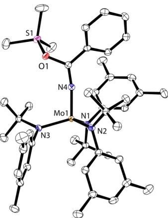
Figure 1. The molecular structure of 2 is shown with thermal displacement ellipsoids at the 50% probability level. Hydrogen atoms have been omitted for clarity. Crystal parameters are P2/n: a = 19.3 Å, b = 11.5 Å, c = 21.1 Å, β = 99.2°, and a crystallographically imposed twofold axis relates the two halves of the molecule. The crystal was grown from a mixture of HMDSO and MeCy in the presence of MesCN.
Table 1. Comparison of internuclear distances (Å) for [(μ-N2)[Mo(N[t-Bu]Ar)3]2]n+ (n = 0, 1, 2)
Compound 2 2 2[B(ArF)4] 2[B(ArF)4]2
Space Group P2/n P21/n P21/n P21/n N–N 1.212(2) 1.217(2) 1.239(4) 1.265(5) Mo–N 1.868(1) 1.870(2) 1.872(2) 1.835(3) 1.841(3) 1.798(2) Mo–Mo 4.9476(5) 4.958(2) 4.9151(6) 4.8599(5) Mo–N[t-Bu]Ar (avg.) 1.985(2) 1.986(2) 1.956(3) 1.931(3)
N5 Mo2 N4 N6 N8 N7 N3 Mo1 N1 N2
Figure 3. A second molecular structure obtained for 2 is shown with thermal displacement ellipsoids at the 50% probability level. Hydrogen atoms have been omitted for clarity. Crystal parameters are P21/n: a = 20.7 Å, b = 11.3
Å, c = 31.3 Å, β = 99.9°. The crystal was grown from a mixture of n-pentane and HMDSO.
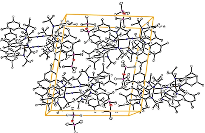
To obtain more detailed structural data for 2 than in the prior EXAFS study, single crystals of 2 were grown for X-ray diffraction. When solutions of 1 in a mixture of MesCN/MeCy/HMDSO were stored under an atmosphere of N2 at –35 °C, we obtained purple crystals of 2 suitable for X-ray diffraction (Figure 1). In the crystal structure, 2 equiv of HMDSO pack with each equiv of 2 (Figure 2). The six anilide ligands are arranged with the tert-butyl groups directed toward the center of the molecule that features a linear MoNNMo core: Mo–N–N, 179.87(14)°. Three anilide ligands are arranged in a trigonal conformation around each Mo center, with the three aryl substituents forming a C3 propeller. The crystallographic C2 axis bisects the MoNNMo core, requiring the two C3 propellers to turn with the same chirality. The metrical parameters obtained via single-crystal X-ray diffraction (Table 1) are in close agreement with previously obtained EXAFS data for frozen solutions of 2. The EXAFS data indicated a linear MoNNMo core defined by a Mo–Mo separation of 4.94 Å and N–N internuclear distance of 1.19(2) Å.10
We found that 2 could also be crystallized from solutions of 1 in n-pentane/HMDSO when stored under N2 at –35 °C (Figure 3). The X-ray structure obtained using crystals so obtained indicated that n-pentane was incorporated into the crystal packing. This second molecular structure of 2 has a pseudo-C2 axis, although no crystallographically imposed symmetry element bisects the molecule; each atom is crystallographically independent. Comparison of the two X-ray crystal structures reveals no significant differences in the molecular structure of 2 (Table 1).
Computational studies predicted that 2 exists as a triplet (S = 1) at 20 °C when the anilide ligands adopt the observed, trigonal arrangement.44-46,49,50 These predictions agree with the previous experimental observation that (μ-N2)[Mo(N[t-Bu]Ph)3]2 exists as a triplet (S = 1) at 20 °C.10 However, the proposal that
2 and (μ-N2)[Mo(N[t-Bu]Ph)3]2 should exhibit similar magnetic properties was recently challenged.45 It
Magnetic Moment ( µ B) Temperature (K) 0 50 100 150 200 250 0.0 0.2 0.4 0.6 0.8 0.0 1.0 2.0 χ T (cm 3 Mol -1 K) 300
Figure 4. SQUID magnetometry shows the dependence of the magnetic moment of 2 upon temperature at an applied field of 0.5 T. These susceptibility data were fit using two distinct magnetic models: a spin Hamiltonian for an S = 1 state with g = 1.69 and D = 42 cm–1 (solid blue), and a Bleaney-Bowers model with g = 1.98 and 2J = –15.6
cm–1 (dashed red). Contributions made by temperature-independent paramagnetism were subtracted.
0 . 0 2 . 0 4 . 0 6 . 0 8 . 0 1 . 0 0.2 0.4 0.6 0.0 βB/kT M × 10 ( ge N β) 1 . 2 0.1 0.3 0.5 5 . 0 T 2 . 5 T 0 . 5 T 0.7
Figure 5. Variable-field–variable-temperature molar magnetization data for 2. Magnetization data were fit to a spin Hamiltonian for an S = 1 state with g = 1.69 and D = 42 cm–1 (solid blue), and to the Bleaney-Bowers model with g
= 1.95 and 2J = –15.5 cm–1 (dashed red). Contributions made by temperature-independent paramagnetism were
away from the observed structure, and that this ligand rotation coincides with a change in the magnetic ground state. The resulting change in the calculated singlet-triplet gap was dramatic: 1922 cm–1 for 2 compared to 585 cm–1 for (μ-N2)[Mo(N[t-Bu]Ph)3]2.45 To test this startling prediction, magnetic studies now have been carried out on 2.
To experimentally address the magnetism of 2, the variable-temperature bulk magnetism of 2 was measured by SQUID magnetometry.54 A plot of μ
eff vs. T plateaus at a maximum value of μeff = 2.40 μB (Figure 4). This value is lower than the expected spin-only value of 2.83 μB corresponding to a triplet (S = 1) spin system.55-57 Moreover, the magnetic moment rapidly declines when the temperature is reduced below 50 K. To further interrogate this magnetic behavior at low temperatures, magnetic data were acquired on a single sample at three fields (0.5, 2.5, and 5.0 T) over a temperature range of 0–250 K. The plot of molar magnetization (M) vs. βB/kT reached a different maximum value for each field strength (Figure 5). This finding demonstrated that the decline of the magnetic moment at low temperatures is due to sizable zero-field splitting of a triplet ground state.58
The variable-temperature magnetic susceptibility data were fit to both the Bleaney-Bowers equation and an S = 1 spin Hamiltonian using the julX software package (Figure 3).59 Only the S = 1 model successfully accounts for the field-dependence of the molar magnetization, therefore, confirming that 2 is a ground state triplet. Using this magnetic model, we found a zero-field splitting parameter, D = 42 cm–1, and the gyromagnetic ratio, g = 1.69. The positive sign of the zero-field splitting parameter, D, indicates that the ms = 0 level of the triplet state lies lower in energy than the ms = –1, 1 levels. At low temperatures and low magnetic fields, the ms = –1, 1 levels are depopulated, and the magnetization is correspondingly decreased. The g value of 1.69 is lower than the free electron value, reflecting the axial anisotropy that is suggested by the value of D.60 Moreover, the value obtained for g predicts a maximum spin-only magnetic moment of 2.39 μB (via μeff = g × (S(S+1))1/2), which agrees well with the observed value near 300 K. Therefore, we conclude that 2 has an isolated triplet (S = 1) ground state that is best described by a 42 cm–1 separation between the low-lying m
s = 0 and degenerate ms = –1, 1 levels in the absence of an applied field.
The fit of our magnetic data to an S = 1 spin Hamiltonian suggests a magnetic axial anisotropy that is not readily explained by the coupling of two d1 Mo centers through a linear, μ-N
2 bridge. As a result, other magnetic models were considered. One alternative model has recently been proposed by Holland and Münck, and applied as a magnetic model for (µ-N2)[Fe(β-diketiminate)]2.61 These coworkers proposed that α and β electrons are asymmetrically shared across the FeNNFe core. This magnetic model formally places more β spin-density on an N22– bridge, while the α spin-density is primarily localized on the two metal centers. The result is a three-spin magnetic model, in contrast to the two-spin model that
would arise from two metal centers indirectly coupled through an innocent bridge.62 Application of the Holland/Münck magnetic model to 2 results in the coupling of two d2, Mo4+ ions through an N
22– bridge. Thereby, interaction between the two S = 1, Mo4+ and the S = –1, N22– local magnetic sites results in the net S = 1 spin-state found for 2. Furthermore, anisotropic exchange between the two Mo4+ ions and the neighboring N22– bridge provides a mechanism for the large axial anisotropy present in 2.60 The Mo4+ oxidation state was previously suggested by near-edge X-ray absorption spectroscopy data acquired on
2.10 A magnetic model that complements this data is attractive as it presents a unified description of the electronic structure of this molecule.
Mechanism of Thermal N–N Bond Cleavage. A zig-zag transition state structure, 2‡, has been proposed
as part of a mechanism for the required transit between the triplet and singlet electronic surfaces that relate 2 and 2 equiv of 3 (Scheme 1).10,44,49,63,64 This transition-state model is a common feature among theoretical analyses of thermal N–N bond cleavage by 2. Additionally, analogous zig-zag structures have been proposed for the dimerization of two terminal nitrides to form a μ-N2 complex.24,65-68 For these reasons, it is noteworthy that the diamagnetic conformer of 2, having two anilides rotated by approximately 90° away from the experimentally-determined structure, which was located by Stranger and coworkers, contains both this MoNNMo zig-zag structure and a longer N–N bond than was measured by single-crystal X-ray diffraction.45-48 Although this computationally predicted structure for 2 agrees neither with the structural nor magnetic data obtained from authentic samples of 2, we still found the structural relationship between the putative zig-zag transition state en route to cleavage of the N–N bond and this proposed geometry intriguing.45,46
Rotation of one or more anilide ligands has previously not been considered as a structural feature of the zig-zag transition state, 2‡. Via ligand rotation, one of the metal π-symmetry (with respect to the μ-N
2 ligand) orbitals is destabilized and the orbital degeneracies that exist in pseudo-C3 coordination geometries are lifted. If one could show that ligand rotation were coupled to the formation of a zig-zag structure of 2‡, then this would be of mechanistic interest with regard to N
2 cleavage. In this regard, one expects the barrier to ligand rotation in 2 to be greater in energy than for less sterically crowded (μ-N2)[Mo(N[i-Pr]Ar)3]2. Interestingly, (μ-N2)[Mo(N[i-Pr]Ar)3]2 has never been directly observed as an intermediate in the N2-cleavage reaction carried out by HMo(η2-Me2CNAr)(N[i-Pr]Ar)2.69,70 The accordingly inferred instability of (μ-N2)[Mo(N[i-Pr]Ar)3]2 contrasts sharply with the properties of 2, which can be isolated and studied as a pure material. We have suggested that facile N2 cleavage by (μ-N2)[Mo(N[i-Pr]Ar)3]2 indicates that this compound more readily accommodates geometric changes along the reaction coordinate than does 2.71,72
The structure of (μ-N2)[Mo[(R)N(CH2)2]3N]2 (R = Me2[t-Bu]Si) has been compared with the structure of 2 previously.10 The two compounds have magnetic moments consistent with an S = 1 state and similar
structural parameters. However, (μ-N2)[Mo[(R)N(CH2)2]3N]2 does not undergo thermal fragmentation with N–N bond cleavage.53 We suggest that the chelating arms of the [(R)N(CH
2)2]3N ligand inhibit rotation about the Mo–Narm bond. If ligand rotation is important for accommodating transit between the triplet and singlet spin-states, then fundamental differences in the reaction chemistry of these two closely related molecules might be explained in terms of ancillary ligand structural constraints. Alternatively, this difference might also be the result of the apical-nitrogen donor that is present in (μ-N2)[Mo[(R)N(CH2)2]3N]2 but absent in 2.73
Solid-State Stability of 2 and Structure of Crystalline 3. In solution, 2 readily fragments to yield 2
equiv of 3 (t1/2 ≈ 30 min, 25 °C).10 Having obtained for the first time samples of 2 as single crystals, we became curious as to whether the extended crystal lattice would confer additional stability to 2.74-79 Crystals of 2 (ca. 0.25 × 0.20 × 0.20 mm), grown from n-pentane/HMDSO, were stored at 20 °C under light petroleum oil for 24 hours. After that time, the crystals continued to diffract, and the unit cell was measured. The measured unit cell parameters in P21/n were unchanged in comparison to those found for fresh crystals that had been analyzed 24 hours earlier. These crystals were additionally suspended in Nujol oil and monitored by UV-vis spectroscopy at 20 °C over 22 hours. During that time, no change occurred in the absorbance spectrum. These two observations suggest that in comparison to solutions or amorphous solids, the extended structure of the crystal lattice stabilizes 2 with respect to fragmentation.80
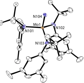
The terminal nitride, 3, formed by thermal fragmentation of 2, has not been structurally characterized in the past due to a severe crystallographic disorder. This disorder results in diffraction patterns that appear orthorhombic, and masked lower-symmetry solutions. A satisfactory solution to the X-ray data has now been found by Peter Müller in the space group P21/n.81 This solution was found for a data set collected from a crystal of 3 grown from n-pentane/Et2O at –35 °C. It was found that slow cooling of this pale yellow crystal from 20 °C to –173 °C was essential to prevent cracking of the crystal, allowing X-ray diffraction data to be collected. The solution to this data contains four crystallographically independent molecules per asymmetric unit, two of which are highly disordered, accounting for 16 molecules per unit cell. Each molecule of 3 approximates C3 symmetry in the solid state, as the aryl rings are staggered in the same direction (Figure 6). The analogous compound, N≡Mo(N[t-Bu]Ph)3, is not subject to the same crystallographic disorder, and its X-ray crystal structure has been previously reported.10 Therefore, the metrical parameters of this compound may be compared to those of 3. For 3, the Mo≡N bond length is 1.651(4) Å while the average Mo–N[t-Bu]Ar bond length is 1.964(4) Å. These values are closely approximated by those found for N≡Mo(N[t-Bu]Ph)3 for which the Mo≡N internuclear distance is 1.658(5) Å and one Mo–N[t-Bu]Ph distance is 1.979(2) Å.10
N101 N104
N103
N102 Mo1
Figure 6. The molecular structure of 3 is shown with thermal displacement ellipsoids at the 50% probability level. Hydrogen atoms have been omitted for clarity.
Redox Chemistry of (μ-N2)[Mo(N[t-Bu]Ar)3]2. We envisioned that by removing 2e– from 2, the
corresponding formal d2-d2 compound should be thermally stable because too few electrons are present to engage in 6e– reductive cleavage of the N–N bond. Moreover, a thermally stable, dicationic compound might be useful for the storage and in situ generation of 2. With isolated 2 in hand, the 2e– oxidation was carried out by the addition of 2 to a solution containing 2 equiv of [Cp2Fe][B(ArF)4] (Cp = η5-C5H5, ArF = 3,5-C6H3(CF3)2). When the oxidation is carried out in Et2O, (μ-N2)[Mo(N[t-Bu]Ar)3]2[B(ArF)4]2,
2[B(ArF)
4]2, is collected by filtration as a red powder in 98% yield (Scheme 2). Powders or CH2Cl2 solutions of 2[B(ArF)
4]2 may be stored at 20 °C for more than 5 days without significant decomposition. Reduction of 2[B(ArF)
4]2 to return 2 was effected by the soluble reducing agent K2COT (COT = C8H8).82 This reducing agent was desirable because it is soluble in THF83,84 and has a sufficient reduction potential to carry out both reduction steps to form 2 while avoiding reduction of 2 to form 2 equiv of [K][NNMo(N[t-Bu]Ar)3].85-88 Reduction of 2[B(ArF)4]2 by K2COT proceeds rapidly in THF solutions to form 2 as the only molybdenum-containing product (Scheme 2). Using this procedure, 2 may be obtained in 85% isolated yield, after separation from the K[B(ArF)4] and COT byproducts.
Two reversible 1e– processes are observed in the cyclic voltammogram of 2[B(ArF)
4]2 (Figure 7).89,90 These are assigned to the 22+/2+ couple at –320 mV and 2+/2 couple at –1260 mV, where Cp
2Fe+/0 = 0 mV (Table 2). The 2+/2 couple has previously been observed in the cyclic voltammogram of 2.16 From a qualitative point of view, 2 is about as reducing as Cp2Co.91
Table 2. Electrochemical potentials measured using [2][B(ArF)
4]2. All data in mV vs. Cp2Fe+/0.
Electrolyte Solution 22+/2+ 2+/2 2/2–
0.1 M [N(n-Bu)4][B(C6F5)4]/THF –320 –1260 measured not
0.5 M [N(n-Bu)4][PF6]/THF –332 –1140 –2250 2.0 M [N(n-Bu)4][PF6]/MeCN –377 –1190 –2530 Scheme 2. 0 -300 -600 -900 -1200 -1500 -1800 Potential Difference (mV) vs. Cp2Fe+/0 1 µA ic ia
Figure 7. The cyclic voltammogram of 2[B(ArF)
4]2 in
0.1 M [(N(n-Bu)4][B(C6F5)4]/THF89,90 shows two
reversible redox events. Assignment of each event is given in the text.
ArF = 3,5-(CF3)2C6H3 K2COT [FeCp2] [B(ArF)4] 2 2[B(ArF)4]2 2+ 2[B(ArF) _ 4] 2 N[t-Bu]Ar Ar[t-Bu]N Mo N Ar[t-Bu]N Ar[t-Bu]N N[t-Bu]Ar Mo N N[t-Bu]Ar N[t-Bu]Ar Ar[t-Bu]N Mo N Ar[t-Bu]N Ar[t-Bu]N N[t-Bu]Ar Mo N N[t-Bu]Ar
The separation between the two reversible 1e– processes observed in the cyclic voltammogram is related to the ΔG° for the comproportionation between 2 and 22+ to form 2 equiv of 2+.92-94 From the peak separation of 0.94 V, the equilibrium constant for this reaction was calculated to be Keq = 1.4 × 1016.93-96 Comproportionation served as a viable synthetic route to (μ-N2)[Mo(N[t-Bu]Ar)3]2[B(ArF)4], 2[B(ArF)4]: Addition of 2[B(ArF)
4]2 to a solution of 2 rapidly formed the mixed-valent compound, 2[B(ArF)4], which was isolated as a cranberry-red solid in 95% yield (Scheme 3). Proton NMR spectra of 2[B(ArF)
4] show a broad tert-butyl resonance centered at 6.0 ppm. Addition of either 2 or 2[B(ArF)
4]2 to solutions of
2[B(ArF)
4] broadens the resonances observed by 1H NMR spectroscopy, as is expected for degenerate electron transfer.97-99 We discovered that 2+ is formed when 2 is dissolved in CDCl3 as this solution quickly changes in color from purple to cranberry-red. Proton NMR, UV-vis, and Raman spectroscopy data support this conclusion; however, the identity of the counter-anion has not been investigated.
Scheme 3. 2 + 2[B(ArF) 4]2 2 2[B(ArF) 4] 2+ _ [B(ArF)4] N[t-Bu]Ar Ar[t-Bu]N Mo N Ar[t-Bu]N Ar[t-Bu]N N[t-Bu]Ar Mo N N[t-Bu]Ar For 2[B(ArF)
4], the magnetic moment of 1.96 μB is consistent with one unpaired electron. This value, which is higher than the expected spin-only value of 1.73 μB, may indicate an orbital contribution from a 2E ground state (approximate C
3 symmetry is assumed) to the observed magnetic moment;100-102 however, care should be taken when interpreting these magnetic data because the measurement requires a large diamagnetic correction, χdia = –1.29 × 10⁻³ cm3 Mol–1 (χM = χobs – χdia).55
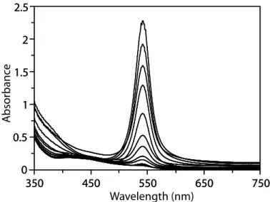
400 600 800 0.0 0.25 0.5 0.75 1.0 1.25 Absorbance Wavelength (nm)
Figure 8. A spectroelectrochemical stack plot shows the conversion 2 → 2+ → 22+ in 0.5 M [N(n-Bu)
4][PF6]/THF
in 0.5-s intervals.
To further characterize the redox couples interrelating 2, 2+, and 22+, the 2e– oxidation of 2 was monitored spectroelectrochemically, allowing the visible transition of each chromophore to be compared in the same solvent and under the same experimental conditions.103,104 The oxidation of 2 in 0.5 M [N(n-Bu)4][PF6]/THF was monitored by UV-vis spectroscopy, while holding the spectroscopic cell at a potential of –200 mV. A stack plot of the UV-vis spectra, taken in 0.5-second intervals, shows the decay of 2, which absorbs at 544 nm, accompanied by the growth of 2+ absorbing at 506 nm (Figure 8). Changes
in the absorbance are less dramatic as 2+ is oxidized to form 22+ because both species absorb strongly at 506 nm; however, the spectral features near 300 nm differ between the two. The spectral assignment for
2+ was confirmed by measuring the UV-vis spectrum of 2+ that was electrochemically generated from 22+ in an optically transparent thin-layer electrochemical cell.105,106 The small energy differences between the optical bands seen for 2, 2+, and 22+ suggest a shared electronic transition among these three complexes. A detailed discussion of these optical spectra is given in the next chapter.
Solid State Structure of 2[B(ArF)
4]. Crystals of 2[B(ArF)4] for X-ray analysis were grown by vapor
diffusion of n-pentane into THF at 20 °C. All atoms are crystallographically independent in the space group P21/n, and the two Mo–N distances around the μ-N2 ligand, Mo(1)–N(7) and Mo(2)–N(8), distances are equivalent, within statistical error (Table 1, Figure 9). The MoNNMo core is nearly linear with Mo–N–N angles of 179.8(3)° and 178.7(3)°. A distortion breaking the trigonal symmetry around the MoNNMo core might be either small or dynamic effect that is not observed.107-109
N5 Mo2 N4 N6 N8 N7 N3 Mo1 N1 N2 B1
Figure 9. The molecular structure of 2[B(ArF)
4] is shown with thermal displacement ellipsoids at the 50%
The symmetrical bonding about the MoNNMo core in 2[B(ArF)
4] contrasts other mixed-valent μ-N2 complexes that exhibit asymmetrical bonding about the μ-N2 ligand.110,111 Such complexes typically have a strong absorbance in the IR spectrum, whereas for 2[B(ArF)
4] the N–N stretching mode is only Raman active (vide infra Figures 11, 12).110 The symmetric bonding about the μ-N
2 ligand in 2[B(ArF)4] is comparable with [(μ-N2)(M(NH3)5)2]5+ (M = Ru, Os), which have Raman active, but IR inactive bands corresponding to the N–N normal mode. Therefore, structural characterization of 2[B(ArF)
4] is consistent with a Robin-Day class III system in which the unpaired electron resides in a molecular orbital that is delocalized across the N–N bridge and is symmetrically shared by both metals.92,112 Absorbance bands in the near-IR region (700 – 3000 nm) were not located for 2[B(ArF)
4]. The lack of intense near-IR bands is consistent with the classification of 2[B(ArF)
4] as a class III mixed-valent complex—for which these bands can become exceedingly weak, hence unobserved.92
Solid State Structure of 2[B(ArF)
4]2. Crystals of 2[B(ArF)4]2, grown from THF/Et2O/n-hexane at –35 °C,
were suitable for X-ray diffraction. The molecular structure of 2[B(ArF)4]2 is symmetric about a crystallographic inversion center that is located on the N–N internuclear vector (Figure 10). The inversion center relates the two C3 propellers formed by the staggered aryl rings, conferring a pseudo-S6 geometry to the 22+ ion. The short Mo–Mo distance of 4.86 Å suggests a congested ligand environment about the MoNNMo core (Table 1). Steric crowding is also evident in 1H NMR spectrum at 20 °C as two distinct resonances are observed for both the aromatic ortho and aryl-methyl protons. These protons become magnetically inequivalent when the dynamic process that interconverts the two possible enantiomers defined by the C3 aryl propellers is sufficiently hindered.
The N–N internuclear distance is a commonly used marker of N2 activation when it is coordinated to a metal;2,113 therefore, it is worthwhile to compare the structures of 2[B(ArF)
4]2, 2[B(ArF)4], and 2. The N–N internuclear distance is longest in 2[B(ArF)
4]2, 1.265(5) Å, while the N–N distance is ca. 0.026 Å shorter for 2[B(ArF)4] or ca. 0.051 Å shorter for 2. The opposite trend is found for Mo–N internuclear distances;
2 has the longest Mo–N separation, 1.87 Å, when compared to the Mo–N distance in 2[B(ArF)
4], 1.835(3) Å, or 2[B(ArF)
4]2, 1.798(2) Å. Both trends indicate that the μ-N2 ligand becomes more activated by removing 2e– from the π bonding MoNNMo core of 2.113
Activation of N2 is generally achieved by reducing the N2, and it is noteworthy to recognize that a number of dicationic μ-N2 compounds are described in the literature. Schrock has reported the electrochemistry of (μ-N2)[M((4-t-BuC6H4)NCH2CH2)3N]2, M = Mo, W.52 For the case of W, the neutral μ-N2 complex was cleanly oxidized by either 1e– or 2e– to afford isolable products; however, crystals suitable for X-ray diffraction studies were not obtained for these compounds. The compound
N1 Mo1 N2
N3
N4
B1
Figure 10. The molecular structure of 2[B(ArF)
4]2 is shown with thermal displacement ellipsoids at the 50%
probability level. Hydrogen atoms have been omitted for clarity.
[(μ-N2)(W(dmpe)Cp*)2][B(C6F5)4]2 (Cp* = η5-(CCH3)5, dmpe = 1,2-(Me2P)2C2H4), formed upon exposure of [(η7-C
5Me3(CH2)2)(dmpe)W(H)2][B(C6F5)4] to N2, has an N–N separation of 1.22(1) Å and a W–N distance of 1.888(5) Å while the W–N–N angle is nearly linear, 176(7)°.114 The dizwitterionic compound (μ-N2)[Fe((i-Pr)2PCH2CH2)3BPh]2 shows activation of the N2 ligand in its N–N distance of 1.138(6) Å and Fe–N separation of 1.815(5) Å.24 A recent EPR/Mössbauer study concluded that this compound is best described as an Fe(I)/Fe(I) ground state septet.115 These examples demonstrate that
2000 1800 1600 1400 1200 1000 Raman Shift (cm-1) R aman In tensit y (%) 0 20 40 60 80 100 20 40 60 80 100 0 1000 1500 2000 2500 3000 R aman In tensit y (%) Raman Shift (cm-1) 0 20 40 60 80 100 20 40 60 80 100 0
Figure 11. (left) Resonance Raman spectra (λex = 514.5 nm) of 2[B(ArF)4]2 in CH2Cl2. (right) Raman spectra
(λex = 785 nm) of 2+ in CDCl3. In the spectrum shown, 2+ was generated by the addition of 2 to CDCl3. For both sets
of spectra, the spectrum for the 15N isotopomer is plotted above that for the natural abundance sample.
compound is best described as an Fe(I)/Fe(I) ground state septet.115 These examples demonstrate that marked reduction of the μ-N2 ligand may be present even when bound between two positively charged metal centers.
Raman Spectroscopy. Raman spectroscopy is a common marker of activation of the N2 ligand,2,113 and
Raman shifts are known to correlate well with N–N internuclear separation for a number of compounds containing the N2 unit.10,116 The extent of activation of the N2 ligand is typically measured against free N2 which has a N–N separation of 1.0975 Å and Raman shift of 2331 cm–1.117-119 To complement the trend in N–N internuclear distance for 2n+ (n = 0, 1, 2) as observed by X-ray crystallography (Table 1), Raman spectroscopy was carried out on these compounds.
Resonance Raman performed on 2[B(ArF)
4]2 (λexcite = 514.5 nm) showed only one intense feature at 1349 cm–1 that was assigned to the Stokes shift for N–N polarization (Figure 11). This assignment was confirmed by the Raman shift for [15N-2][B(ArF)
4]2 that is found at 1305 cm–1, 44 cm–1 less energetic than the shift observed for the lighter isotopomer. This decrease in the Raman shift upon isotopic labeling agrees with the change calculated for a harmonic oscillator.120 Raman spectroscopy of 2[B(ArF)
4] (λexcite = 785 nm) showed an intense Stokes shift at 1503 cm–1 that was shifted to 1438 cm–1 for the 15N
3500 3000 2500 2000 1500 1000 500 88 90 92 94 96 98 100 Tr ansmittanc e (%) Wavenumbers (cm-1) 3500 3000 2500 2000 1500 1000 500 60 70 80 90 100 Tr ansmittanc e (%) Wavenumbers (cm-1) 3500 3000 2500 2000 1500 1000 500 65 70 75 80 85 90 95 100 Tr ansmittanc e (%) Wavenumbers (cm-1) 3500 3000 2500 2000 1500 1000 500 60 70 80 90 100 Tr ansmittanc e (%) Wavenumbers (cm-1)
Figure 12. Infrared spectra as thin films of 2 (upper left), 2[B(ArF)
4]2 (upper right), 2[B(ArF)4] (lower left); and
2[B(ArF)
4] in CDCl3 (lower right). Note that the Raman active νNN is not detected in the infrared spectrum. Resonant
absorbance bands are listed below.
For 2 (film, KBr): 2956.1, 2918.0, 2860.2, 1596.6, 1583.0 (s), 1456.6, 1352.0, 1283.4 (s), 1176.4 (s), 1147.3 (s), 1071.32, 1038.9, 1016.8, 957.7 (s), 937.2 (s), 882.7 (s), 846.7, 788.5, 716.6 (s), 686.8 (s), 677.2, 576.7 cm–1.
For 2[B(ArF)4]2 (film, KBr): 2983.8, 2919.9, 2868.7, 1603.4, 1583.2, 1462.2, 1354.3 (s), 1277.6 (s),
1161.7 (s), 1126.7 (s), 940.9, 887.9, 838.6, 710.5, 682.5, 669.3 cm–1.
For 2[B(ArF)4] (film, KBr): 2974.21, 2924.6, 2866.0, 1600.67, 1584.56, 1353.2 (s), 1276.7 (s), 1162.4 (s),
1126.4 (s), 1041.0, 1016.8, 998.2, 940.7, 885.5, 838.2, 713.1, 681.9, 669.3 cm–1.
isotopomer. The observed isotope shift of 65 cm–1 is greater than the calculated shift of 51 cm–1, indicating a degree of anharmonic character in the vibration. Anharmonic potentials have been associated with a dynamic Jahn-Teller distortion.108,121
The Raman spectrum of 2 contains the N–N bond polarization at 1630 cm–1.10 The lower energy polarizations of 1503 cm–1 and 1349 cm–1 for 2[B(ArF)
4] and 2[B(ArF)4]2, respectively, are consistent with a weakening of the N–N bond upon oxidation of 2.2,113 These Raman shifts may be plotted as a function of N–N internuclear distance (Figure 13);116 moreover, the three data points may be extrapolated to the Raman shift for gaseous N2.117-119 The correlation of Raman shifts with N–N bond length is consistent with the observation that the overall complex structure remains unchanged by removing either 1e– or 2e– from 2: only Mo–N and N–N distances of the MoNNMo core are changed by altering the charge.
Correlation Between Charge and Structure. The experimental, X-ray structure of 2[B(ArF)
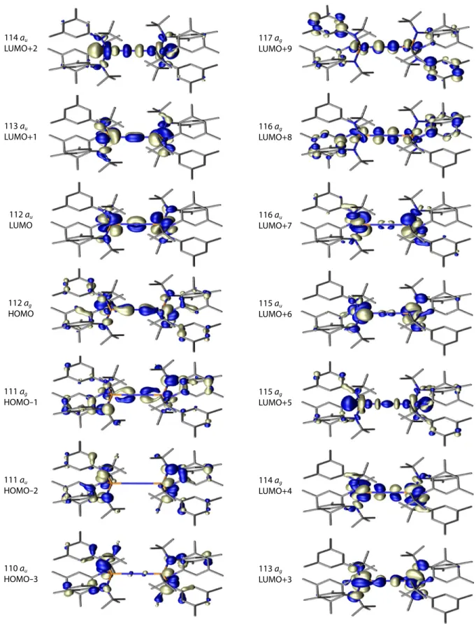
4]2 was used to provide an initial geometry for density functional theory (DFT) calculations to find a theoretically optimized structure for 22+. This calculation provided a pictorial view of the frontier orbitals of 22+ (Figure 14). The HOMO corresponds to the bonding interaction between the Mo d orbitals and the π* orbital of N2, whereas the LUMO is NN π bonding in character. Such an analysis leads one to expect that that population of the LUMO of 22+ by either 1e– or 2e– will enhance the bonding between the two nitrogen atoms. This interpretation is nicely supported by the X-ray and Raman data described above: upon reduction of 2[B(ArF)
4]2 to either 2[B(ArF)4] or 2, shortening of the N–N bond is observed by X-ray crystallography and a higher energy νNN is observed by Raman spectroscopy.
The calculated electronic structure of 22+ indicates that the LUMO+2 is a low-lying σ symmetry orbital having the appearance of two out-of-phase dz2 molybdenum-based orbitals coupled by the NN
bridge. The LUMO+3 is a π-symmetry orbital that appears to have both NN and MoN antibonding character. However, the metal-localized lobes in LUMO+3 are not coplanar with the nitrogen-based orbitals. Both of these orbital sets contain a substantial contribution from the metal, and the low energy of these orbitals indicates that they are best viewed as either weakly antibonding or nonbonding. Strongly antibonding, π-symmetry orbitals of the MoNNMo core are actually much higher in energy.
The orbital model presented here is consistent with previous treatments.10,20,122-124 One pertinent example is [(μ-N2)(Ru(NH3)5)2][BF4]4, which contains a short N–N bond of 1.124 Å (νNN = 2100 cm–1). The lack of strong N–N bond activation in this complex has been attributed to filled orbitals of Ru–N antibonding character—an alternative description for the orbital set that we suggest is NN bonding.124-126 This supports the general conclusion that N2 activation is not merely a consequence of the number of electrons presented by the metal center but the symmetry of the orbitals that these electrons occupy.
1.10 1.15 1.20 1.25 1400 1600 1800 2000 2200 2400 Raman Shift (cm -1 ) N-N Distance (Å) N2 22+ 2+ 2
Figure 13. Resonance Raman shifts plotted as a function of N–N internuclear distance. The best fit line through 4 points is given by ν(r) = –5859r + 8762, R2 = 1.000, σ = 1.04 cm –1. Raman shifts are given in the text, and bond
lengths are listed in Table 1.
LUMO, LUMO+1 LUMO+2 LUMO+3, LUMO+4 HOMO, HOMO-1
Figure 14. Selected frontier orbitals for 22+ show the N–N bonding character of the LUMO. Orbitals are drawn at
an isosurface value of 0.037. For simplicity, only one orbital is drawn for pairs of orbitals that are close in energy and transform under the same irreducible representation in the S6 point group. The all-bonding MoNNMo orbital is
Conclusions
The previously elusive solid-state structure of 2 has now been determined. Having obtained an unambiguous structure for 2, we answered a number of questions concerning the structure and magnetism of this linear, bimetallic μ-N2 complex. Moreover, we have suggested that ligand rotation about the Mo–Nanilide bond may play an important role in reducing the kinetic barrier toward N–N bond cleavage by 2 under thermal conditions.
The structural and spectroscopic signatures of 2 were compared to those for 2[B(ArF)
4] and
2[B(ArF)
4]2. In doing so, a counter-intuitive trend in activation of the μ-N2 ligand was uncovered: Commonly used measures of N–N bond activation indicated that removing 1e– or 2e– from the MoNNMo core of 2, a complex known to undergo thermal N–N bond cleavage, results in a reduction of the N–N bond. This correlation of charge with N–N bond strength was rationalized by a DFT model of the electronic structure within the MoNNMo core. As a result, this study demonstrates the role of orbital-symmetry in tuning the bonding across an N2 bridge.
Synthetic Procedures
General Remarks. All manipulations were carried out under an atmosphere of purified nitrogen in a
Vacuum Atmospheres Model MO-40M glovebox equipped with the QP-30 accessory, or by standard Schlenk techniques.127,128 Inside the MO-40M glovebox the ambient temperature ranged from 18–22 °C. All glassware was oven-dried at a temperature above 150 °C for at least 12 h and allowed to cool under dynamic vacuum prior to use. Celite, alumina, and 4 Å sieves were activated by heating to a temperature greater than 180 °C under a dynamic vacuum for 2 d (celite) or 5 d (alumina and 4 Å sieves). Et2O, n-hexane, n-pentane, and toluene were bubble degassed with nitrogen and forced, under positive pressure, through a column of activated alumina followed by a column of activated Q5.129 CH
2Cl2 was bubble degassed with nitrogen and forced, under positive pressure, through two columns of activated alumina.129 THF was taken from an Aldrich Pure-Pac and under positive pressure passed through two columns of activated molecular sieves. THF was additionally stirred over sodium metal which was removed by filtration through activated alumina or celite prior to use. MeCN was taken from an Aldrich Sure-Seal bottle, filtered through a column of activated alumina (4 × 3 cm), and degassed under a dynamic vacuum. HMDSO was distilled from dark purple solutions of sodium benzophenone ketyl. MeCy was distilled from CaH2. All solvents were stored over 4 Å sieves. C6D6 was degassed and stored over 4 Å sieves for 3 d prior to use. CD2Cl2 and CDCl3were refluxed over CaH2 for 24 h then distilled and stored over 4 Å sieves. 1H and 13C NMR shifts were referenced against residual solvent resonances (for C
6D6, 7.16 and 128.39 ppm; for CD2Cl2, 5.32 and 54.00 ppm; for CDCl3, 7.24 and 77.23 ppm). 19F NMR spectra were externally referenced to CFCl3 (δ = 0 ppm). Positive ion ESI-MS were obtained using a Bruker Daltonics APEXIV, 4.7 T Fourier Transform Ion Cyclotron Resonance Mass Spectrometer. Combustion analysis was performed by Midwest Microlab, LLC (Indianapolis, IN). Literature procedures were used for the preparation of [Cp2Fe][B(ArF)4]130, K2[C8H8]131, [N(n-Bu)4][B(C6F5)4]89,132.
Preparation of (μ-N2)[Mo(N[t-Bu]Ar)3]2, 2.10,11,16 As an orange powder, Mo(N[t-Bu]Ar)3 (5.081 g,
8.143 mmol) was loaded into a 250 mL Erlenmeyer flask. This solid was then dissolved in 125 mL of THF with rapid stirring. The stir bar was removed from the flask, and the flask capped with a rubber septum. The flask was then stored at –35 °C for 10 d under N2. The flask was removed from the freezer every 3 d to readmit N2 into the flask. Over the first 7 d, the color of the solution became dark purple but few solids had precipitated. After 10 d, a large amount of powder had precipitated and 3.145 g of 2 was isolated by filtration of the mixture. The solids were washed with n-pentane (10 mL × 2). The filtrate was concentrated to 50 mL and stored at –35 °C for an additional 7 d to afford each of the 3 additional crops (Overall, 4.760 g, 3.730 mmol, 91.6%). Purple solids were washed with MeCN, in which 2 is entirely insoluble, and dried to constant mass prior to magnetic studies. 1H NMR (600 MHz, C
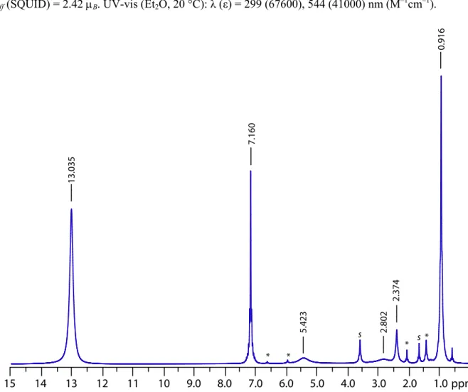
6D6, 20 °C): δ = 13.04 (s, Δν1/2 = 60 Hz, 54 H, C(CH3)3), 5.42 (s, Δν1/2 = 250 Hz, 6 H, ortho-Ar), 2.80 (s, Δν1/2 = 280 Hz,
6 H, ortho-Ar), 2.37 (s, Δν1/2 = 20 Hz, 6 H, para-Ar), 0.92 (s, Δν1/2 = 6 Hz, 36 H, Ar–CH3) ppm. μeff (SQUID) = 2.42 μB. UV-vis (Et2O, 20 °C): λ (ε) = 299 (67600), 544 (41000) nm (M–1cm–1).
14 13 12 11 10 9.0 8.0 7.0 6.0 5.0 4.0 3.0 2.0 1.0 * * s s * * ppm 15 13.035 5.423 2.802 2.374 7.160 0.916 Figure 15. 1H NMR (600 MHz, C
6D6, 20 °C) spectrum of 2. THF and 3 are marked with s or *.
Preparation of (μ-N2)[Mo(N[t-Bu]Ar)3]2[B(ArF)4]2, 2[B(ArF)4]2, by Oxidation of 2. At –116 °C, to a
rapidly stirred, blue solution of [Cp2Fe][B(ArF)4] (1.796 g, 1.712 mmol, 2 equiv) in 50 mL Et2O was added a solution of 2 (1.09 g, 0.856 mmol) in 40 mL Et2O over 2 min. The mixture became dark brown in color after approximately 25 mL of the solution of 2 has been added. The intensity of the brown color grew over the next 5 min. To the mixture was added 40 mL of thawing n-pentane (–130 °C) to quickly precipitate the product as a red powder. The product was then isolated by filtration. The solids were washed with n-pentane (30 mL × 4) and then Et2O (20 mL × 4). Drying solids under a dynamic vacuum yields the product, 2[B(ArF)
4]2 (2.530 g, 0.842 mmol, 98.4 %), mp = 135-140 °C (dec). 1H NMR (500 MHz, CD2Cl2, 20 °C): δ = 7.70 (s, 16 H, ortho-ArF), 7.54 (s, 8 H, para-ArF), 7.17 (s, 6 H, para-Ar), 6.71 (s, 6 H, ortho-Ar), 4.50 (s, 6 H, ortho-Ar), 2.35 (s, 18 H, Ar–CH3), 2.17 (s, 18 H, Ar–CH3), 1.41 (s, 54 H, C(CH3)) ppm. 13C NMR (125 MHz, CD2Cl2, 20 °C): δ = 162.0 (q, ipso-ArF), 147.3 (s, ipso-Ar), 139.8 (s,
![Figure 9. The molecular structure of 2[B(Ar F ) 4 ] is shown with thermal displacement ellipsoids at the 50%](https://thumb-eu.123doks.com/thumbv2/123doknet/14747035.578562/35.918.237.683.451.1002/figure-molecular-structure-ar-shown-thermal-displacement-ellipsoids.webp)
![Figure 10. The molecular structure of 2[B(Ar F ) 4 ] 2 is shown with thermal displacement ellipsoids at the 50%](https://thumb-eu.123doks.com/thumbv2/123doknet/14747035.578562/37.918.250.668.105.803/figure-molecular-structure-ar-shown-thermal-displacement-ellipsoids.webp)
![Figure 1. Molecular structure of 4-t-Bu[OTf] shown with 50% probability ellipsoids. Hydrogen atoms have been omitted for clarity](https://thumb-eu.123doks.com/thumbv2/123doknet/14747035.578562/90.918.272.654.495.986/figure-molecular-structure-probability-ellipsoids-hydrogen-omitted-clarity.webp)