DEVELOPMENT, CHARACTERIZATION AND APPLICATIONS OF
MAGNETORHEOLOGICAL FLUID BASED 'SMART' MATERIALS ON THE
MACRO-TO-MICRO SCALE
by
SURAJ SHARADCHANDRA DESHMUKH
B.Tech., Chemical Engineering (2001)
Indian Institute of Technology, Bombay
M.S., Mechanical Engineering (2003)
Massachusetts Institute of Technology
Submitted to the Department of Mechanical Engineering
in Partial Fulfillment of the Requirements for the Degree of
Doctor of Philosophy in Mechanical Engineering
at the
MASSACHUSETTS INSTITUTE OF TECHNOLOGY
February 2007
0 2006 Massachusetts Institute of Technology
All rights reserved
Signature of A uthor...
...
Department of Mechanical Engineering Sentember 29. 2006
C ertified by...
Gare".
cKinley
Professor of Mechanical Engineering
,A T1,1-.'.-'
A ccepted by...
...
Lallit Anand
Professor and Chairman, Department Committee on Graduate Students
MASSACHUSETS INSTrTUTEOF TECHNOLOGY
APR 19 2007
LIBRARIES
Development, Characterization and Applications of Magnetorheological Fluid based 'Smart' Materials on the Macro-to-Micro scale
by
Suraj Sharadchandra Deshmukh
Submitted to the Department of Mechanical Engineering on September 29, 2006 in partial fulfillment of the requirements for the Degree of Doctor of Philosophy in
Mechanical Engineering
ABSTRACT
Magnetorheological fluids belong to the class of field-responsive fluids that undergo large, reversible and fast changes in their rheological properties when acted upon by an external magnetic field. 'Smart' or controllable composite materials have been obtained by doping polymers, foams, fabrics etc. with these field-responsive fluids. The resulting composite materials have potential applications in numerous fields ranging from adaptive energy absorption, automotive crash protection to microfluidic valves, mixers and separation devices.
A series of stable magnetorheological (MR) fluids have been systematically characterized
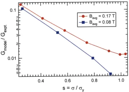
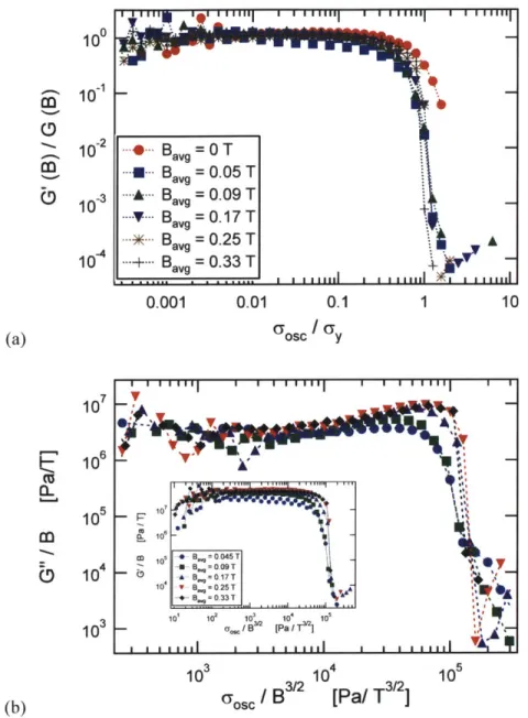
under steady shearing, creep and large amplitude oscillatory shear (LAOS) flow conditions. A rheometer fixture for applying nearly uniform magnetic fields up to 0.4 T has been fabricated to measure both steady-state and transient changes in the fluid properties under applied fields. Stable MR fluids with a markedly improved dynamic response (yield stress as a function of magnetic field) compared to commercial fluids have been formulated by increasing the constituent particle size and by stabilizing the system against sedimentation. A new "soft-glassy rheology" model has been used to model the fluid response time and visco-elasto-plastic response under creep conditions and oscillatory loadings. The experiments and model show that the evolution of chain
structure and plastic collapse in these suspensions exhibits a universal scaling with the
dimensionless stress s = U/% .
Structure evolution, pattern formation and dynamics of MR fluid flow in microchannel
geometries has been analyzed using high-speed digital video microscopy. In order to elucidate the
mechanisms that control MR structure formation, experiments have been performed while
varying the magnetic field, particle size, channel geometry, concentration and fluid composition.
Excellent qualitative agreement has been obtained with Brownian Dynamics simulations and
useful scalings based on interplay of magnetostatic & viscous forces have been extracted to
understand the field-dependent fluid response on the macro & micro scale.
Novel MR elastomeric materials and microparticles have been synthesized by doping
photo-curable or thermo-curable polymers with field-responsive fluids. A high-throughput
micromolding technique for synthesis of controllable particles of anisotropic shapes and sizes has
been developed. Flexible and permanent chain-like structures have also been synthesized using
amidation chemistry. Potential microfluidic applications such as field-responsive valves, mixers
and separation devices using these 'smart' materials have also been investigated.
Thesis Supervisor & Committee Chair:
Gareth H. McKinley (Professor of Mechanical Engineering)
Thesis Committee Members:
Patrick Doyle (Professor of Chemical Engineering) Alice Gast (Professor of Chemical Engineering) T. Alan Hatton (Professor of Chemical Engineering)
ACKNOWLEDGEMENTS
I would like to express my deepest gratitude to my advisor, Prof. Gareth H. McKinley, for his expert guidance and constant encouragement. I have loved bouncing ideas off him and he
has always patiently listened and encouraged me to work on them. I have learned a lot from his
vast knowledge and will always admire his friendly nature and witty humor.
This thesis would not have been possible without the support of my family throughout
these years. I am also indebted to my friends who have made every moment of my life here
exciting and precious.
I would like to thank the Non-Newtonian Fluids group for their invaluable suggestions and all the people at Hatsopoulos Microfluids Laboratory for making this lab such a fun place to
be in. Finally, I would like to acknowledge the financial support received from the Institute of
Table of Contents
Abstract
3
Acknowledgements
5
Chapter 1
Introduction
11
1.1 FIELD-RESPONSIVE FLUIDS 111.1.1
Background
11
1.1.2
Magnetorheological (MR) vs Electrorheological (ER) Fluids
13
1.1.3
Challenges for MR/ ER Fluids
14
1.2 MOTIVATION 15
Chapter 2
Magnetorheological Fluids: Bulk Characterization
19
2.1 COMPOSITION 19
2.1.1
Laboratory Formulation of MR fluids
23
2.2 APPARATUS FOR CHARACTERIZATION OF MR FLUIDS 28
2.2.1
Rheometer. Previous fixture designs
28
2.2.2
Custom Rheometer Fixture Design
30
2.3 STEADY STATE FLOW BEHAVIOR 39
2.3.1
Background
39
2.3.2
Steady State flow behavior of commercial fluids
42
2.3.3
Steady State flow behavior of laboratory formulated MRfluids
44
2.3.4
Yield stress comparison of different MR fluids
46
2.3.5
Wall slip and migration of sample
48
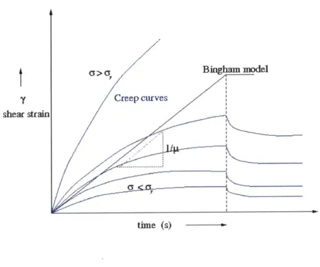
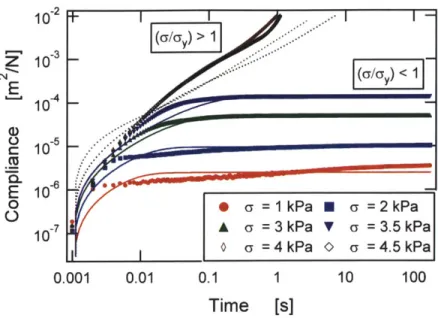
2.4 TIME-DEPENDENT RHEOLOGY: CREEP 50
2.5 VISCO-ELASTO-PLASTIC MODEL 55
2.5.1
Previous models
for
yield stress fluids
55
2.5.2
Models for "soft-glassy materials"
56
2.5.3
Comparison of model predictions with experimental creep data
62
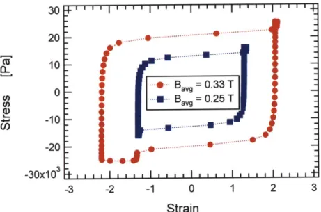
2.7
LISSAJOUS CURVES (LAOS SHAPES) 732.8 CONCLUSIONS 78
Chapter 3 Adaptive Energy Absorbing Materials 79
3.1
CONCEPT AND DEVELOPMENT OF THE ADAPTIVE MATERIAL80
3.2
APPLICATION POTENTIAL FOR THE ADAPTIVE MATERIAL83
3.2.1 Automotive energy management 83
3.2.2 Protective armor 85
3.2.3 Challenges 88
3.3
CONCLUSIONS88
Chapter 4 Structure Formation and Dynamics of MR Fluid Flow in
Microchannels 89
4.1 MODELING: PARTICLE INTERACTIONS
90
4.1.1 Magnetic Interactions 90
4.1.2 Hydrodynamic Interactions 92
4.1.3 Brownian Motion 93
4.1.4 Dimensionless groups 93
4.2 EXPERIMENTAL MATERIALS AND METHODS
95
4.2.1 Background 95
4.2.2 Materials 95
4.2.3 Experimental setup: High-Speed Video Microscopy 96
4.2.4 Image Analysis Technique 100
4.3
AGGREGATION PHENOMENA: QUIESCENT CASE103
4.4 AGGREGATION PHENOMENA: PRESSURE-DRIVEN FLOW
110
4.4.1 Background 110
4.4.2 Effect of Magnetic field strength on Structures 113
4.4.3 Effect of Flow rate on Structures 116
4.4.4 Effect of volume fraction on Aggregation phenomena 119
4.4.5 Effect of geometrical ratios on structures 123
4.6 CLUSTER ANALYSIS: OTHER TECHNIQUES
135
4.7 COMPARISON OF EXPERIMENTAL RESULTS WITH BROWNIAN DYNAMICSSIMULATIONS
140
4.8 CONCLUSIONS
149
Chapter 5 Microscale Applications of 'Smart' Fluids & Materials 151
5.1 SYNTHESIS OF MAGNETIC MICROSTRUCTURES 152
5.1.1 Magnetic Chains 152
5.1.2 Anisotropic Monodisperse Magnetic Microparticles 160
5.2 MAGNETIC MICROSCALE APPLICATIONS
168
5.2.1 Magnetic microfluidic separation chips 168
5.2.2 Magnetic microrheology probes 170
5.2.3 Magnetic microfluidic actuators and valves 170
5.2.4 Magnetic microfluidic mixers 180
5.3 CONCLUSIONS
184
Chapter 6 Conclusions and Future Work 185
6.1
CONCLUSIONS 1856.2
FUTURE WORK188
Chapter 1
Introduction
Adaptive materials or 'smart' fluids that can be user-controlled in response to external
conditions have potential applications in a wide variety of fields ranging from energy
management in automobiles, protective armor, sporting equipment and 'artificial muscles' to
microfluidic actuation, biomaterial separations, micromechanical sensors and microrheology
probes.
'Smart' materials with their adaptive capabilities and integrated designs can be actively
controlled in response to the external environment. The field of 'smart' materials is
interdisciplinary and comprises of a wide range of technologies such as piezoelectric materials,
electrostrictive and magnetostrictive materials, shape memory alloys (SMA), conducting
polymers, biometric gels and field-responsive fluids (Schwartz, 2002).
1.1
Field-Responsive Fluids
1.1.1 Background
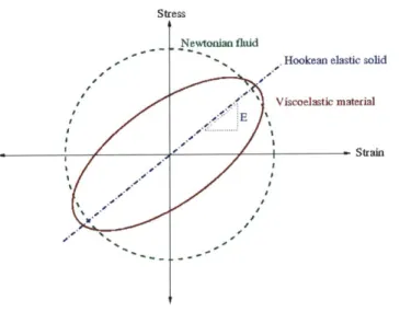
Field-responsive fluids (FRFs) may be characterized as materials that undergo large
changes in their rheological (i.e. flow) properties such as viscosity, elasticity or plasticity in
response to changes in magnetic, electric or stress fields. Magnetorheological fluids ('MR'
fluids), electrorheological (ER) fluids, shear-thickening fluids, liquid crystals and ferrofluids
(a)
E0(c)
Unpolarized light beam Polarizer 5and elEctrode~Polarized
light Ldquid crystal F' andol plteI (d) (e) MirrorFigure 1.1 Field responsive fluids (a) Magnetorheological fluids (b) Electrorheological fluids (Parthasarthy and Klingenberg, 1996) (c) Ferrofluids (Rosensweig, 1985) (d) Shear-thickening fluids (Barnes, 1989) (e) Liquid crystals (McMurry and Fay, 2004).
MR fluids and ferrofluids both show dramatic & reversible changes in response to
external magnetic fields. MR fluids are typically composed of micron-sized particles while the particles constituting ferrofluids are typically tens of nanometers in size. Ferrofluids which are
increasing magnetic field though they maintain a fluid-like state (figure 1.1(c)). MR fluids, on the
other hand, can reversibly change between a free-flowing liquid and a semi-solid state within few
tens of milliseconds in the presence of a magnetic field (figure 1.1(a)). Electrorheological (ER)
fluids are electric field analogs of MR fluids and show rapid and large changes in their
rheological behavior in response to an applied electric field (figure 1.1(b)). Shear-thickening
fluids respond to increasing deformation fields with large and reversible increase in their
viscosity (figure 1.1(d)). Liquid crystals align in the presence of electric fields and hence show
changes in their optical properties (figure 1. 1 (e)).
1.1.2 Magnetorheological (MR) vs Electrorheological (ER) Fluids
Magnetorheological fluids have been the focus of many studies since they can provide a
simple, rapid-response interface between electronic controls and mechanical systems. They were
first discovered and developed by Jacob Rabinow (1948) at the US National Bureau of Standards.
W. M. Winslow (1947) is credited with the initial development of ER fluids.
The ultimate strength of MR fluids depends on the saturation magnetization of the
dispersed particles and hence pure iron (saturation magnetization 2.15 T), or iron/cobalt alloy
(saturation magnetization 2.4 T) particles are chosen. The maximum energy density in ER fluids,
on the other hand, is determined by the dielectric breakdown (i.e. critical electric field when
conduction paths within the fluid lead to destructive breakdown) for the particles and is about 2
orders of magnitude less than the MR fluids. The maximum yield strength of ER fluids is hence
around 2-5 kPa as compared to nearly 150 kPa obtained for MR fluids'. The active fluid needed
for MR devices is thus much less as compared to ER devices resulting in much smaller devices.
However, giant electrorheological (GER) suspensions comprising of nanoparticles coated with a
low conducting material were recently reported of breaking this theoretical upper bound for ER
ER fluids are hampered by a number of issues such as surface charge, electrode
polarization, adsorbed water and field inhomogeneities (Promislow and Gast, 1995). The
constituent particles are stabilized in the medium by the use of surfactants and other additives. ER
fluids are sensitive to these additives and other impurities, while these do not affect the
polarization mechanism in MR fluids leading to enhanced stability, lubricity etc. Further, temperature variations do not have a strong effect on magnetic polarization so that MR fluids can
operate over a much larger temperature range (-40 'C to 150 0C) as compared to ER fluids. Hence, though MR fluids have appeared in number of commercial applications, ER fluid based
applications have remained elusive.
However, since iron particles comprise most of the MR fluids, the fluids tend to be much
heavier as compared to ER fluids and particle settling becomes an important concern.
1.1.3 Challenges for MR/ ER Fluids
ER fluids have been plagued by a number of problems and their inferior rheological
properties and poor long-time stability as compared to MR fluids have prevented their use in
commercial products. MR fluids on the other hand have a huge cost limitation and many more
applications would quickly become commercial if the material cost could be reduced
(Klingenberg 2001).
The saturation magnetization of MR particles, which is a material property attained when
all the magnetic moments in the sample are aligned, is the limiting factor for determining the
strength of MR fluids and a higher strength would clearly make many new applications viable.
Since iron particles usually comprise an MR fluid, particle settling is an important concern
though a viscoplastic medium or an absorbent matrix has been used to overcome these problems
to a certain extent. In-use-thickening (IUT) or increase in the off-state force with time, as
particles undergo wear and tear, is a significant challenge for the use of these fluids (Carlson
MR fluids, which reduce the agglomeration of particles with time, by use of mechanically hard
magnetic particles and some anti-wear additives. However, much research effort is needed in
understanding field-responsive fluid rheology before these limitations and challenges can be
overcome and commercialization of new applications can be facilitated.
1.2
Motivation
The primary focus of this thesis work is to develop controllable materials by using
field-responsive fluids by themselves or in adaptive 'smart' composites for doping and modifying
existing material properties. These materials can then conform to the demands of the user and
satisfy different requirements under a variety of external conditions.
A wide range of materials such as polymers, cellular solids, fabrics, plastics etc. can be 'doped' with MR/ ER fluids to obtain field-controllable materials that show dramatic & reversible
changes in their mechanical properties in response to magnetic or electric fields. As an example, a
'smart' material consisting of a cellular solid impregnated with a field-responsive fluid such as a
magnetorheological fluid can prove beneficial as an adaptive energy-absorbing material
(Deshmukh and McKinley, 2007). Energy absorption, dissipation or shunting is an extremely
important issue in automobiles, armor, protective gear and sporting equipment and controllable
materials can provide an elegant energy management solution.
As an example, consider the car headrest, which is required to be soft and compliant so it
is comfortable to the passengers but at the same time, during a rear-end crash, it is required to be
rigid enough to absorb passenger head-impact energy and prevent whiplash. This is further
complicated by the fact that different passengers, such as an adult or child, require different
amounts of impact energy to be absorbed. A material that is rigid enough to satisfy adult impact
energy requirements usually is too stiff to cushion a child's head impact without harming it. New
WG 17) introduce stringent impact protection requirements for car headrests, knee-bolsters, A, B,
C pillars to be implemented in the next few years and this is a major concern in the automotive industry. A tunable headrest such as a magnetorheological fluid impregnated cellular solid can
potentially resolve this 'conflict of stiffness' problem.
Another potential area of application of such tunable materials is as an 'artificial muscle'
in robotic motion or as a microfluidic actuator. It may be possible to 'dope' PDMS, which is
widely used in manufacturing of microfluidic devices, using magnetorheological fluids so that it
can be controlled and actuated using external magnetic fields.
In microfluidic devices and applications, field-responsive fluids can be used as 'smart'
fluids in bio-fluid analysis and DNA separation chips. The structure and patterns formed by MR
fluids in microchannel geometries can be controlled by controlling the magnetic field which can
then be used to separate or analyze DNA of different sizes (Doyle et al., 2002).
However, in order for these applications to satisfy the functional requirements of various
applications, it is equally important to understand the properties of field-responsive fluids and
their property changes with variation in magnetic field, particle concentration and other
parameters. Hence, a large part of this work is focused on characterizing and modeling the
behavior of these field-responsive fluids, in particular magnetorheological fluids, on the micro
and macro scale under different conditions.
A flowchart detailing the organization of this thesis work is shown in figure 1.2. The dissertation can be broadly divided into three parts - namely, synthesis or formulation of
magnetorheological fluids, characterization and modeling of fluid behavior and application
development. Since a fundamental understanding of the microstructural properties is vital to
further our understanding of the bulk behavior, the characterization and application development
of magnetorheological fluids and MR fluid based 'smart' composite materials is further organized
Adaptive energy absorbing materials --- ApplijCation~s -F croscale applications (Chapter .5)
(chapter 3)
* Explore use of MR fluids and MR fluid doped materials as
/ Impact testing (Texture Analyzer, Drop ball test) valves and mixers (Section 5.2)
(Section 3. 1) * Explore various MR PDMS configurations (Section 5.2.2) e Characterization under variation of field, particle e Different shapes and sizes of particles as mixers (Section loading (MR fluid vol. fraction) (Section 3.1) 5.1.2)
SExplore use In protective armor and clothing (Section
Characterization of MR fluid behavior MR Fluid Characterization of Structure and Dynamics o
on the macroscale: Bulk Rheology Characterization fluids inmicrochannel geometries High Speed Video-Microscopy (Chapter 4) (Chapter 2)
Experimental setup to capture dynamics (Section 4.2) esign of rheometer fixture (Section 2.2) 9 Capture particle structure formation for
* Experiments * Various MR fluids (Section 4.3)
" Steady State flow (Section 2.3) * Different fields (0-0.25T ), I and Ma numbers (Section
4.4.1-" Slip studies: gap dependence (Section 2.3.4) 443)
* Creep flow (Section 2.4) * Different CIP particle concentrations (Section 4.4.4)
" Oscillatory shear flow including LAOS (Section e Different particle sizes (Section
4.4,5)
2.6-2.7) * Mechanism behind the dynamics of structure formation
* Modeling of rheological behavior (Section 4.5)
* Yield stress dependence on the magnetic field * Comparison with Brownian Dynamics Simulations (Section
4. 7)
(subquadratic) (Section 2.3.3)
Visco-elasto-plastic model (Section 2.5)
MRF based on mixture of sizes
MRF Fluid Synthesis -- * MRF based on chain structures (wormlike) (Section 5.1.1)
* Bigger size (Section 2.1)
Figure 1.2 Thesis organization flowchart. The thesis work is divided into 3 main sections
-synthesis or formulation of MRF's, characterization and application of MR fluid and
fluid-doped composite materials.
The detailed sectional organization of this thesis work is described in figure 1.2. The bulk
rheological characterization of magnetorheological fluids in a range of flow conditions that are
encountered in applications is described in chapter 2. Chapter 3 describes the application potential
of magnetorheological fluids and MR fluid doped materials as an adaptive energy management
solution in automotive applications, protective armor and sporting equipment. Chapter 4
discusses the structure and dynamics of magnetorheological fluids on the microscale and the use
of high-speed video microscopy to elucidate the mechanisms of aggregation phenomena that
as microfluidic chips, 'artificial muscle' actuators and micro sensors are explored in detail in
Chapter 2
Magnetorheological Fluids: Bulk
Characterization
Magnetorheological fluids ('MR fluids') belong to the class of so-called "smart" or
controllable materials (Ginder, 1996). A number of commercially-available and research-stage
applications utilize the controllable nature along with the large, reversible changes in the
rheological properties of magnetorheological fluids (Carlson, 1999; Klingenberg, 2001). Understanding the bulk rheological behavior and properties of these fluids is vital to these
applications and also necessary for optimizing and designing composite "smart" materials doped
with MR fluids (Deshmukh and McKinley, 2007).
2.1
Composition
Magnetorheological fluids are typically 20-50 % (by volume) suspensions of colloidal
particles, usually 1-10 microns in size, in a carrier fluid such as a mineral oil, silicone oil, water
or glycerol etc (Genc and Phule, 2002; Carlson, 2001). The magnetizable particles are soft
magnetic solids (Ginder et aL., 1996) with a high saturation magnetization in the case of MR
fluids while in the case of ER fluids they have a high dielectric constant and a suitable
conductivity (e.g. alumina) (Klingenberg et al., 1989; Klingenberg and Zukoski, 1990; Larson, 1999).
B
Figure 2.1 MR suspensions (2 vol%, 50 ptm dia. iron particles in silicone oil) before and after
application of a magnetic field (Klingenberg 2001).
The saturation magnetization is the maximum induced magnetic moment that can be
obtained in a magnetic field (Ginder, 1996). The magnetic properties of any material are
represented by B-H curves and are described by the equation
B = poprH (2.1)
where B is the magnetic induction, H is the magnetic field, po is the permeability of
free space and p, is the relative permeability of the material. MR fluid particles in contrast to
ferrofluids (as described in section 1.1.1) are micron-sized and hence consist of multiple magnetic
domains. In the absence of an applied magnetic field, the particles possess very small net dipole
aggregation in an applied field (Ginder, 1996). The application of a field causes domain-wall
motion and alignment of magnetic domains along the field direction and thus interparticle
magnetic attraction (please refer to section 4.1 for particle interaction models). Hence, a high
saturation magnetization allows us to obtain the largest magnetic moments and hence the
strongest interparticle attractions, which in turn defines the magnetorheological effect (Larson,
1999; Ginder, 1996; Carlson, 2001).
Mostly, carbonyl iron particles have been used in preparation of MR suspensions though
other formulations using ferromagnetic or ferrimagnetic particles, like magnetite (Fe304 ),
Fe - Co alloy and Ni - Zn ferrites have also been described (Carlson, 2001; Chin et al., 2001;
Genc and Phule, 2002). Ferromagnetic materials exhibit a long-range ordering phenomenon at the
atomic level, which causes the unpaired electron spins to line up parallel with each other in a
region called a domain. Ferrimagnetic particles, like ferromagnetic materials, hold a spontaneous
magnetization below the Curie temperature. However, this is due to opposing but unequal
magnetic moments of the atoms on different sublattices. Kormann et al. (1996) have studied
magnetorheological fluids made of nanosized ferrite particles, which are typically used to
formulate a ferrofluid. MR fluids have also been made from superparamagnetic particles (e.g.
polystyrene particles studded with nanometer size iron oxide inclusions) dispersed in a solvent
(Fermigier and Gast, 1992). Superparamagnetic particles are soft ferromagnetic or antiferromagnetic particles that do not possess any residual magnetization.
However, the MR fluids based on particles with smaller size have a weaker
magnetorheological effect. This is because, for an equivalent volume of magnetizable powder, the
surface area is inversely proportional to the particle size.
S I
-2- Oc - (2.2)
V
d
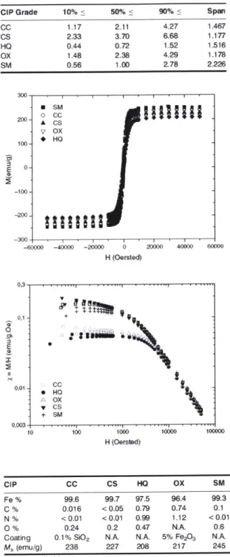
CIP Grade 10% < 50% < 90% < Span CC 1.17 2.11 4.27 1.467 CS 2.33 3.70 6.68 1.177 HO 0.44 0.72 1.52 1.516 OX 1.48 2.38 4.29 1.178 SM 0.56 1.00 2.78 2226 E 0 E USIM A CS V OX 100- HO 0- -100--200. -300--- 60000 -40000 -20000 0 20000 40000 600 H (Oersted) 0,3 . , . , , , ,. . , . . 01 99 0,01 - cc 0 HO A OX S + SM )003- . . ... , , , . . . , , .... 10 100 1000 H (Oersted) 10000 00 100000 CIP CC CS HO OX SM Fe % 99.6 99.7 97.5 96.4 99.3 C % 0.016 < 0.05 0.79 0.74 0.1 N % <0.01 <0.01 0.99 1.12 <0.01 0 % 0.24 0,2 0.47 NA 0.6
Coating 0.1% Si)2 NA N.A. 5% Fe2O3 NA
M, (emu/g) 238 227 208 217 245
N.A.: not applicable.
Figure 2.3 Magnetization curves and composition for carbonyl iron particles of different sizes
Thus, even though a larger size of particles leads to particle settling and destabilization
issues, micron sized carbonyl iron particles (saturation magnetization -2.03 Tesla) are typically
used for MR fluid formulations. A number of proprietary additives such as surfactants and
thixotropic agents are added to promote stabilization of particles. Chin et al. (2001) have used
nanosized ferromagnetic particles (Co -)y - Fe203) and CrO2 particles to enhance dispersion
stability. Nanostructured silica and surfactants such as oleates and stearates have been added in
earlier works for improving redispersibility (Phule and Ginder 1999, U.S. Patent No. 5,985,168).
For improved stabilization of MR fluids against gravity, a viscoelastic medium having a low yield
stress like grease has also been used as the continuous phase (Rankin et al. 1999). LORD Corp
commercially produces numerous formulations of MR fluids using different types of carrier
fluids'.
2.1.1 Laboratory Formulation of MR fluids
A severe limitation of commercially available MR fluids for industrial applications is their high cost ($600/ litre). Also, these fluids are found to be plagued by stability issues as the
particles settle over a period of time leaving a clear supernatant liquid. Hence, in this thesis work
stable magnetorheological fluids have been formulated using in-house technology at a fraction of
(a)
(b)
Figure 2.3 SEM images of Carbonyl Iron particles from BASF used in formulation of Magnetorheological fluids (a) I gm (HQ grade) (b) 7 ptm (CR grade)
Carbonyl iron particles (saturation magnetization ~ 2.03T), 1.1 pm in size (BASF Corp.
magnetizable matter in the laboratory formulated MR fluids. SEM images of these Carbonyl Iron
powders are shown in figure 2.2. As can be seen from the figure, the powders are fairly
polydisperse e.g. CR grade of carbonyl iron particles has a particle size distribution of 3-17
microns with a mean diameter of 6.72 microns. Carbonyl iron powder (CIP) is obtained by the
thermal decomposition of iron pentacarbonyl (Fe(CO)5). In the course of the decomposition
process, spherical particles form on a nucleus thereby forming a shell structure2. The
decomposition conditions decide the properties of the particles including the particle size
distribution.
The magnetization curve of these carbonyl iron powders was shown earlier in figure 2.2
(Bombard et al., 2003) and it can be observed that the magnetization of the powder with larger
particle size is much higher (1.5-3 times) than the smaller size carbonyl iron powder.
Polydimethyl siloxane, trimethylsiloxy terminated (PDMS) with a viscosity of 0.1 Pa.s
(Gelest Inc., DMS-T21) formed the carrier base of the MR fluid. Silicone oil is used because of
its low volatility, low dependence of viscosity on temperature and inert nature towards other solid
and liquid constituents. A surfactant, silanol terminated polydimethylsiloxane (Gelest Inc.,
DMS-S21), stabilizes the particles against agglomeration. This surfactant has a -OH terminal group which provides an affinity towards the carbonyl iron particles, while the PDMS part has an
affinity towards the carrier fluid. A PDMS surfactant with an amine terminal group (Gelest Inc.,
AMS- 132) is also found to stabilize the particles in the fluid.
A viscoplastic base, Dow Corning high vacuum grease, which blends well with the carrier fluid is utilized to provide a low off-state yield stress to the MR fluid and prevent the
particles from settling under gravitational forces. A simple force balance gives the yield stress
required in order to prevent the particles from settling
where a is the critical yield stress to prevent settling, r is the radius of particle and p is the density of the particles. The critical yield stress works out to be nearly 0.05Pa for carbonyl iron particles with diameter 1.1 pm and is around 0.16Pa for particles with diameter 7
pm (pp of 7800 kg/m3 for carbonyl iron powder).
Silicone Oil (Gelest Inc.)
2 iigCycles -+40 min. blending
High Vacuum 15% W /W ixgCyl
Grease (Dow Corning)
1 1 Mixing Cycle
(Gelest Inc.) Carbonyl Iron 36% v/v r)A'I
Particles (1.1 microns) '2Mxing Cycles
(BASF)
CMagnetorheological Fluid
1 Mixing Cycle is 3 min. Mixing + Degassing in Conditioning mixer
Figure 2.3 Formulation of a Magnetorheological fluid. A flowchart showing all the
components and mixing steps for formulation of a 36% v/v I pm particle-based MR fluid.
A step-by-step flowchart of the formulation process is shown in figure 2.4. A conditioning mixer (Thinky Corp., AR-100) has been used for both mixing and degassing
purposes. The mixing cycle of three minutes includes a one-minute combined rotation (160 rpm)
2200 rpm. Rheological measurements (figure 2.4) show that the blend of 15wt% grease in
silicone oil has a low yield stress of approximately 0.7Pa in the field-off state, which is sufficient
to prevent the 1.1 ptm carbonyl iron particles from settling.
Using a carrier fluid with higher off-state yield stress, (for example 25wt% blended grease in silicone oil that has a yield stress of a- 4 Pa, instead of the 15wt% blended grease)
as shown in figure 2.4, is found to be sufficient enough to prevent 7 pm carbonyl iron particles
from settling under gravity. The MR fluid thus formulated is observed to have a gel-like
consistency and excellent long-term stability. The yield stress of the MR fluid at a particular
magnetic field strength is expected to increase as the particle size increases because of increased
magnetization. Stability becomes a bigger concern for larger particle sizes, which has been
successfully countered by using the appropriate viscoplastic base.
2 -' 1 11111 I ' ' ' ''''' I ' ' ' ' ' '' ' ' ' ' ''' 100 - Silicone oil (Gelest Inc., DMS -T21, viscosity 0.1 Pa.s) _
6 blended with high vacuum grease (Dow Corning)
4 U) 2-10 -0- 15 wt% grease 6 -U- 25 wt% grease ) 4-0 CO 2-6 4-1 10 100
Shear stress
[Pa]
Ty ~0.7 Pa gy;~4 PaFigure 2.4 Steady shear data for silicone oil blended with grease at different weight fractions
2.2
Apparatus for Characterization of MR Fluids
2.2.1 Rheometer: Previous fixture designs
Field-responsive fluids are characterized by their steady-shear and linear viscoelastic
properties, which can be determined using rheological and optical techniques. A number of
rheological instruments such as capillary viscometer, slit rheometer, stress or strain controlled
rheometer or a light scattering setup with either a parallel-plate arrangement, Couette cell
arrangement or a cone and plate arrangement are used to measure these desired material functions
(Macosko, 1994). R R
Fluid
1 Z R 0fr
rco
Y h
Figure 2.6 'Parallel-disk' and a 'cone and plate' type arrangements for a rheometer used to
determine material properties of complex fluids.
The two most widely used configurations are shown in figure 2.6, in which small
volumes of fluid sample are tested between two coaxial circular parallel plates or between a small
angle cone and plate, under shear, oscillatory or creep flows. A more detailed discussion relating
(r R)
(r R)
the mechanically measured quantities with the desired material functions can be found in the
treatise by Bird et al. (1987).
Rheological properties of MR fluids are also dependent on the magnetic field and
custom-made or commercial attachments to standard rheometers have been used for this purpose.
Li et al. (1999, 2002) and Woliny et al. (2002) have used a commercially available MR cell for
the UDS 200 rheometer with parallel-plate geometry, which generates a magnetic field
perpendicular to the shear direction. Rankin et al. (1999) used a Bohlin VOR rheometer modified
by inserting the rheometer plate shafts through holes drilled into an electromagnetic iron yoke (figure 2.6). A big disadvantage of these designs is that the magnetic field is a function of the gap
between the top and bottom plates and hence it is not possible to perform gap-dependent studies.
D.C. Powr Supply Gaussmeter
To Torque Transducer Insulated Wire
E ectr-megnetk Iro
Suspension
Figure 2.7 Schematic diagram of a Bohlin VOR rheometer modified using a iron yoke
electromagnet (Rankin et al. 1999).
Helmholtz coils have been used by Cutillas et al. (1998) to generate a uniform but low
strength magnetic field in the fluid sample space. Chin et al. (2001) have designed a solenoidal
2.2.2 Custom Rheometer Fixture Design
Two stress-controlled shear rheometers (TA instruments' AR 1000N and AR 2000) are
used to determine the steady-state rheological and linear viscoelastic properties of MR fluids. In
general, a parallel plate (2cm diameter stainless steel plate with a gap height of 0.5 mm)
arrangement and occasionally a cone-and-plate (2cm diameter 44 stainless steel cone)
arrangement is used for the experiments. Since the fluid properties are a strong function of the
magnetic field, a custom-made fixture is designed and built as a removable attachment to the
rheometers for control and generation of a uniform magnetic field in the fluid sample space. The
magnetic field generated is orthogonal to the direction in which the sample is sheared so that the
MR fluid particle chains need to collapse before the sample starts flowing, thus allowing the
measurement of magnetic field-dependent yield stress.
An exploded view of the custom-built MR fluid rheometer fixture is shown in figure 2.8.
The fixture is designed to allow a maximum gap of 1500 microns for the fluid sample between
the top and the bottom plate. The bottom plate (4.52cm diameter) is formed from CRS (Cold Roll
Steel)-1080 (McMaster Carr), which is a soft-magnetic (does not retain residual magnetism when
the applied magnetic field is removed) but mechanically hard material. The outer and inner
housing of the magnetic coil have been machined out of mild steel to concentrate the magnetic
field lines through the sample. The fixture can also be made to snugly fit onto the Peltier plate of
To AR2000
rheometer spindle
Top Cover (Mild
teel)
0.9144cm ID,
12.065cm OD,
0.635cm Thickness
Cone & plate or plate
plate arrangement
for the rheometer
300 turns, AWG
#21 magnetic coil
4.52cm ID, 8.255cm
OD, 5.08cm Height
Steel Housing (Mild
steel, CRS 1080)
10.16cm ID, 12.065cm
OD, 5.715cm Height
To Peltier Plate
(b)
Figure 2.8 (a) SOLIDWORKS model of the custom-built MR fluid fixture for the TA
instruments' AR series rheometers. (b) Fixture setup on the AR2000 rheometer (TA Instruments).
1300 turns of wound AWG #21 (0.7329mm diameter) copper wire (RODON Products Inc.) form the base field-generating coil. FEMM3.2 software has been used to determine the coil
space3. Depending on the area of cross-section (A,) available, the current density (J) is
determined as follows
1,0,1 =1 JAC (2.4)
where I1001 is the total current that is required for the high magnetic field. The copper
wire diameter and the number of turns (N ) is then chosen such that the current per turn (h,,)
doesn't exceed its current carrying capacity as follows
II Jlr = total N (2.5) d 1.1 5A(. dwire IN, N where dwr is the copper wire diameter.
The resulting coil without the use of a cooling water system can then support a maximum
current of 3.OA. A DC power supply (BK Precision Model 1670) provides a variable current from
i-:
0.4
Rheometer fixture
1300 turns coil03-
B vs I calibration 0.3 '0.2
-0> 0.1
0.0
0.0
0.5
1.0
1.5
2.0
2.5
Current
[Amperes]
Figure 2.9 Magnetic field strength (B) in Tesla, obtained in the fluid sample space using the custom-built MR fluid rheometer fixture, as a function of the DC current flowing through it.
A gaussmeter (F.W. Bell Model 5060) with a transverse probe is used to calibrate the
magnetic field versus the input current. FEM analysis is used to validate gaussmeter based experimental measurements and also to test the uniformity of the magnetic field. The magnetic field strength computed from FEM analysis shows a maximum variation of 8% over the fluid sample space. Helmholtz coils could have been used to get a more uniform magnetic field but the field strengths obtained are typically very small (0 -0.025 Tesla) and not suitable for complete characterization of fluid properties (Cutilass et al., 1998). Figure 2.10 depicts the magnetic field lines and flux gradient for the rheometer fixture generated using FEMM 3.2 software. The axisymmetric longitudinal sectional view is color-coded, for example, the shades of green in the fluid sample space observed in the figure depict the magnetic field variation around 0.4 Tesla. A comparison of our in-house built MR fluid fixture for determining rheological properties with other commercial or custom-built fixtures from literature is presented in Table 4.1.
MR fluid
sample space
CRS-1080
forming the
bottom plate
Mild steel
housing
(a)
0 2 4 6 8 10 12 14Radial Distance
[mm]
Figure 2.10 (a) Magnetic field lines and gradients illustrated using a longitudinal section
color-coded for different magnetic fields for the MIT rheometer fixture designed for MR
fluids (I =2.5 Amperes). (b) Variation of magnetic field strength in the fluid sample space as a
function of the current in the coil. A maximum variation of 8% in the magnetic field strength
is computed in a 2cm fluid sample space.
1.626e+000: >1.712e+000 1.541e+000: 1.626e4000 1.455e4000: 1.541e+000 1.370e+000 1.455e4000 1.284e4000 : 1.370e+000 1.198e+000: 1.284e4000 1.113e4000 : 1.198e+000 1.027e+000: 1.113e4000 9.416e-001 .1.027e+000 8.560e-001 9.416e-001 7.704e-001 8.560e-001 6 848e-001 7.704e-001 5.992e-001 : 6.848e-001 5.136e-001 : 5.992e-001 4.280e-001 : 5.136e-001 3.424e-001 : 4.280e-001 2.568e-001 : 3.424e-001 1.712e-001 : 2.568e-001 8.560e-002: 1.712e-001 <1.712e-007: 8.560e-002
Density Plot: IBI, Tesla
. . . I I I... .. .. .. ..
Magnetic field variation - I = 2.5 A
using custom-built fixture - I = 1.9 A
for AR series rheometer - I = 1.25 A: - I=
0.6 A
0.6 0.5 0.4 0.3 0.2 U. I Ca z 0 75 C) a)C
0) (b) 16Reference: Rheometer Fixture type and Maximum
Type of geometry dimensions magnetic
field (B)
Paar Physica Co. UDS 200 Solenoidal coil 0.34 T
Parallel plate geometry Diameter = 20 mm N = 495 turns
Chin et aL. (200 1) ARES (TA Instruments) Solenoidal Coil ~0.33 T Parallel plate geometry Diameter = 0.75 mm
N = 2500 turns
Cutillas et aL. (1998) Shear rheometer Helmholtz coil 0.025 T Parallel plate geometry
Rankin et al. (1999) Bohlin VOR rheometer Electromagnet wound 0.355 T Parallel plate geometry with a coil
N = 1000 turns
Claracq et aL. (2004) ARES (TA Instruments) Inductive coil 0.04 T Cone and plate geometry N = 735 turns
Deshmukh and AR 2000/ 1 OOON rheometer (TA Solenoidal Coil 0.635 T
McKinley (2006) Instruments) Diameter = 8-40 mm
Parallel plate and cone and plate N = 1300 turns arrangement
Table 4.1 Comparison of fixtures, commercially available or custom-built, for determining the
rheological properties of MR fluids.
An improved version of this custom built fixture has also been designed for future use as
a magnetic field attachment for the AR series of rheometers (TA instruments). It uses a tighter
microns earlier), which allows the field lines to be concentrated in the fluid sample space. This
further reduces the weight of the fixture and is easier to manage on a peltier plate with a
maximum normal force rating of 50N.
However, it requires modifications of the rheometer top plate so that the chamfer where
the plate connects to the shaft is removed. These modifications increase the allowance for
different gap sizes in the fluid sample space to 2500 ptm (as compared to 1500 ptm in the original
design) while also increasing the maximum attainable magnetic field (without water cooling) in
the fluid sample space to 0.635 Tesla. The magnetic field variation in the fluid sample space is
increased at these higher magnetic fields and the maximum variation is 10% as compared to 8%
-
Cone/ plate
arrangement for
the rheometer
1300 turns, AWG
#21 magnetic coil
Steel Housing (Mild
steel, CRS 1080)
(a)
MR fluid
sample space
(b)
Figure 2.11 (a) Exploded section view of MIT Rheo-Magnetic fixture for the AR series of
rheometers. (b) Magnetic field lines and gradients illustrated using a longitudinal section
color-coded for different fields at a current of 2.5 Amperes.
1.620e+000: >1.600e+W0 1.440e+000: 1.520e800 1.360e+000: 1.440e+000 1.280e+0: 1.360e40 1.200e+OW: 1.280e+000 1.120e+000: 1.200e4000 1.040e+000: 1.120e4000 9.600e-001 :1.040e4000 8.800e-001 9.600e-001 8.000e-001 8.800e-001 7.200e-001 8.000e-001 6.400e-001 : 7.200e-001 5.600e-001 : 6.400e-001 4.800e-001 5.600e-001 4.000e-001 4.800e-001 3.200e-001 4.000e-001 2.4009-001 3.200e-001 1.600e-001 2.400e-001 8.000e-002: 1.600e-001 <3 950e-007: 8.000e-002
2.3
Steady State Flow Behavior
2.3.1 Background
MR fluids are typically in the liquid-like state with the consistency of motor oil (viscosity
~ 0.1-1 Pa.s) until a magnetic field is applied. The constituent soft magnetic particles then acquire
a dipole moment. The induced dipolar particles then align with the external field relative to the
non-magnetized dispersed phase to form fibrous columns or aggregates as shown in figure 2.1.
The columns need to be broken for the suspension to flow again which gives rise to a yield stress
(i.e. the magnitude of stress at which appreciable deformation takes place without any appreciable
change in the stress (Barnes, 1999)) as a function of the magnetic flux density.
shear thickening (n>1) Bingham fluid (n=1) shear thinning (n <1) shear stress Newtonian fluid shear rate
i
Figure 2.12 Herschel Bulkley viscoplastic model for Field-Responsive fluids where or, is the
yield stress at which the fluid starts flowing and the exponent n describes the non-Newtonian
behavior observed after yield.
The Herschel -Bulkley viscoplastic model is often used to describe this yield stress and
the non-Newtonian behavior observed in FRFs after yield
U-=T-, (B) +/
a>-r77=
kjf
nI ,(2.6)where o-, is the yield stress of the material, r7 is the viscosity,
f
is the shear rate, B is the magnetic field strength, k is the 'consistency index' and n is the power-law exponent (figure2.12).
The yield stress is a function of the applied magnetic field and has been observed up to
-120 kPa for micron size particles at magnetic fields higher than I Tesla (Gene and Phule, 2002). Tang et aL. (2000) have observed a yield stress of 800 kPa for enhanced structures obtained by
compressing the MR fluid along the field direction. MR fluids have been studied extensively
under steady shear flow and representative data is shown in figure 2.13. The dynamic yield
stresses can be determined from such measurements by extrapolating to zero shear-rate (Gene and
103
10QZ AAAA AAAA&*AA AAAA
10 t 00******* CL 10O 0000900*00 %-Po 0 HO=0 a HouO. 16kOe 700 A H6=032kOe y HO=0.48kOe
(a)
Hou064kOe 10-1 11 . 10- 100 101 102y
(s')
103102
e **a H, = O .16kOe 100020
***** * H 3 k Ho & 0.32kOe w HO 0.48k0eW(b)
H 0.64kOa 10.1IFI 10' 100 101 102 i(s")Figure 2.13 Steady shear flow data for a Fe304 in silicone oil MR fluid showing dependence
of yield stress on the magnetic field strength a)
1=
20 % b)f
= 40 % (Chin et al. 200 1).The effect of particle volume fraction on the dynamic yield stress is also evident from
figure 2.13 and o (B) is observed to increase almost linearly with volume fraction at a constant magnetic field (Chin et al. 2001). Experiments have also been carried out for various dispersing
mediums, notably the use of a viscoplastic medium, like grease, to prevent sedimentation of the
constituent particles (Rankin et al. 1999).
At small field strengths the field-induced yield stress is proportional to the square of
magnetic flux density but becomes sub-quadratic with increasing field strength. This occurs
the contact points between the particles (Ginder, 1996). This in turn limits increase of the field
strength in the gaps between the particles and the magnetic field dependence becomes
subquadratic as shown in figure 2.14.
60 50 C- 40 30 20 10 0 0 50 100 150 200 250 300 350 400 H (kAmplm)
Figure 2.14 Graph showing the sub-quadratic dependence of yield stress on the magnetic field
strength for the commercially available MR fluid, MRF - 336AG formulated by LORD Corp4.
2.3.2 Steady State flow behavior of commercial fluids
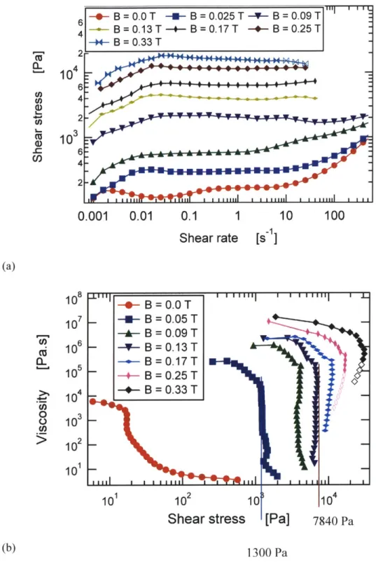
MRF-336AG, a silicone oil based magnetorheological fluid supplied by LORD Corp. and commonly used in automotive suspensions and dampers has been characterized under steady
shear. The silicone oil based MR fluid has been used for characterization as it is inert to
temperature variation and also provides a direct comparison to the in-house formulated MR fluid.
MRF-336AG is composed of 36% v/v carbonyl iron particles or iron-cobalt alloy particles
(-pim) in a silicone oil carrier fluid along with a number of proprietary additives. The rheological
properties of the fluid under steady shear flow for different magnetic field strengths are shown in
figure 2.15. The fluid has a weak yield stress (- 150 Pa) even in the absence of a magnetic field
4 http://www.rheonetic.com
indicating the presence of a thixotropic additive. As the magnetic field is increased, the shear
stress at which the fluid starts flowing also increases as can be observed from figure 2.15. The
yield stress results are reproducible to within ± 5% if a standard test protocol is followed as
outlined below. 104 CL) 2-3 10-2- B=0.025T-- B= .025T 1 2-_-*- B = 0.05 T -1- B = 0.09 T 6 2B = 0.13 T -+-B=0.17T 4 B = 0.25 T -- B = 0.33 T
0.001
0.01
0.1
1
10
100
1000
Shear rate
[s~i]
Figure 2.15 Rheological behavior of MRF-336AG fluid in steady state flow using a 2cm
roughened plate at a gap height of 0.5 mm for different magnetic field strengths.
The rheological behavior of magnetorheological fluids was found to be dependent on the
rest time and the loading conditions like other "soft-glassy" materials and gels. Hence, a standard
pre-test protocol has been developed and used for all the experiments to ensure reproducibility
and eliminate any effects due to thixotropy and rheological aging. The experiments were
performed using a 2 cm diameter roughened plate arrangement. The protocol consisted of loading
the sample onto the rheometer fluid sample space, slowly bringing the top plate to the required
gap while maintaining the normal stress value below I Pa, applying a magnetic field for 30s to
shear rate nominally higher than the zero-field yield stress value. The fluid sample is then
assumed to be free of any dependence on loading history and rest time. This was indeed
confirmed in the test runs.
The experiments have been carried out using 2cm diameter roughened plates and the
magnetic field is varied from 0 to 0.4 Tesla. The test protocol used on the AR2000 rheometer is a
steady state flow step with the shear rate being controlled and varied from 0.001 to 2000 s-1. Five
points are measured per decade of shear rate with the sample being sheared for 60 seconds before
an average value of the torque is recorded.
In order to minimize wall slip, the top and bottom plates of the rheometer are roughened
by coating them with a very thin layer of carbonyl iron particles using a low viscosity glue (Permabond 910 cyanoacrylate) such that the roughness is of the order of the particle size.
However, at higher shear rates there is still migration of the sample out of the plates, similar to
that observed in other yield-stress fluids such as peanut butter, cream cheese etc. (Citerne et al.
2001; Erni P. through private communication). A steady state viscosity plateau after the yield
point is thus not always observed in the samples and the data points where migration of sample is
observed are shown with hollow symbols.
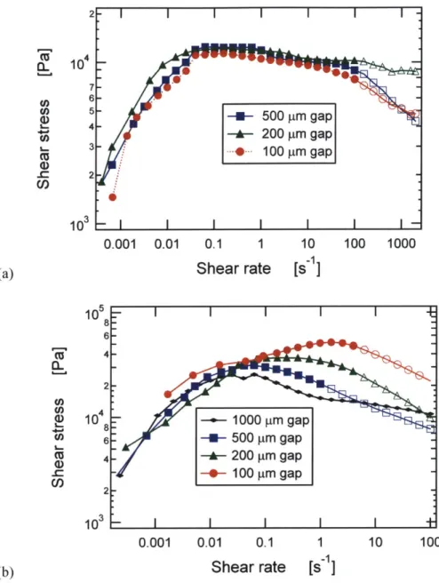
2.3.3 Steady state flow behavior of laboratory formulated MR fluids
The steady state flow behavior of MR fluids based on I ptm carbonyl iron particles
(BASF AG, HQ grade) at 36% v/v is shown in figure 2.16(a). The yield stress or the stress threshold at which the MR fluid starts flowing again is observed to increase with the magnetic
field. Once the stress threshold is overcome the fluid is found to be highly shear thinning with a
drop of 4 to 7 orders of magnitude of viscosity, as shown in figure 2.16(b) for the 7 pm carbonyl
B = 0.0 T -a- B = 0.025 T -- B = 0.09 T 4 --- B=0.13T -- B=0.17T -- B = 0.25 T --- B = 0.33 T
2-10
6 2-3
0.001
0.01
0.1
1
10
100
Shear rate
[s_]
(a) 10 - B = 0.0 T 10 -- B = 0.05 T-. ,4+
B =
0.09 T
106 -- B = 0.13 T CL -+- B=0.17T 105 - -B = 0.25 T 4 _-+s- B = 0.33 T e 10o
3
0 10 C,)>
102 _ 10 1 101 102 10 10 4Shear stress
[Pa]
7840
Pa(b) 1300 Pa
Figure 2.16 MR fluid (36% v/v, 1.1 im CIP) rheological properties under steady shear flow
for different magnetic field strengths.
The creep viscosity at stresses below the yield stress is of the order of 104 - 107 Pa.s 103 Pa.s at
room temperature (Barnes, 1999)). On a microstructure level when the chain and column
structures that form in the presence of magnetic field collapse plastically, the stress threshold is
said to have been overcome and the material starts flowing again displaying a liquid-like behavior
and viscosity of the order of the carrier fluid viscosity (the steady shear viscosity of silicone oil
used for laboratory formulated MR fluids ~ 0.1 Pa.s).
2.3.4
Yield stress comparison of different MR fluids
The magnitude of the yield stress of the MR fluid (r, (B)) is its defining characteristic for most applications and it can be extracted from the steady shear data as illustrated in figure
2.16(b).
30x10
325
20
U Un15
W
10
5
0
0.
00
0.10
0.20
0.30
Magnetic field strength (B) [T]
Figure 2.17 Yield stress comparison for three MR fluids - commercial fluid from LORD
Corp. (MRF -336AG) with laboratory formulated MR fluids (1 mm and 7 tm CIP at 36%
v/v).
MRF (36% v/v 1.1 im CIP)
-U- Lord (MRF-336AG)
- + MRF (36% v/v -7 m CIP)
At the yield point there is a sharp drop in the viscosity due to the collapse of particle
chains in MR fluids and this threshold stress can be read off from the viscosity versus shear stress
plots. As an example, dotted lines in figure 2.16(b) mark the yield stress values for magnetic
fields of 0.09 and 0.17 Tesla.
The variation in the yield stress with the magnetic field calculated for the three fluids thus
calculated is shown in figure 2.17. The yield stress data for the 1 micron carbonyl iron particle
based MR fluid is found to be comparable to the commercial fluid which is not surprising given
the similar sizes of particles. A marginally higher yield stress for the commercial MRF-336AG
fluid is due to the use of iron-cobalt alloy particles that have a higher saturation magnetization
than carbonyl iron particles (2.4T saturation magnetization of iron-cobalt alloy particles as
compared to 2.I T for carbonyl iron particles (Ginder, 1996)).
The yield stress for 7 micron carbonyl iron particle based MR fluid is found to be higher
than commercial or I micron CIP based MR fluids by nearly 50% as measured up to magnetic
fields of 0.4 T. This is due to the higher magnetization of larger particle sizes due to a lower
surface area to volume ratio and hence a smaller amount of low magnetic susceptibility iron oxide
layer on the surface of these particles. Also, a subquadratic dependence of the yield stress with
the magnetic field is observed, as shown in figure 2.17, which is in accordance with the scalings
proposed by Ginder (1996) for the yield stress
J- q 1oM 2 H32 (2.7)
where crY is the yield stress, M, is the saturation magnetization and H is the magnetic
field strength. Since the magnetic susceptibility and hence the magnetization of the 7 micron size
carbonyl iron particles is nearly twice the magnetic susceptibility of 1 micron size particles
(figure 2.2), the 50% (,r =1.414) increase in the yield stress is in good agreement with Ginder's