HAL Id: cea-02144086
https://hal-cea.archives-ouvertes.fr/cea-02144086
Submitted on 29 May 2019
HAL is a multi-disciplinary open access
archive for the deposit and dissemination of sci-entific research documents, whether they are pub-lished or not. The documents may come from
L’archive ouverte pluridisciplinaire HAL, est destinée au dépôt et à la diffusion de documents scientifiques de niveau recherche, publiés ou non, émanant des établissements d’enseignement et de
Effects of porous media on extraction kinetics: Is the
membrane really a limiting factor?
Johannes Theisen, Christophe Penisson, Julien Rey, Thomas Zemb, Jean
Duhamet, Jean Christophe Gabriel
To cite this version:
Johannes Theisen, Christophe Penisson, Julien Rey, Thomas Zemb, Jean Duhamet, et al.. Effects of porous media on extraction kinetics: Is the membrane really a limiting factor?. Journal of Membrane Science, Elsevier, 2019, 586, pp.318-325. �10.1016/j.memsci.2019.05.056�. �cea-02144086�
Effects of Porous Media on Extraction Kinetics: Is
the Membrane Really a Limiting Factor?
Johannes Theisen1*, Christophe Penisson1, Julien Rey2, Thomas Zemb2, Jean Duhamet3* and Jean-Christophe P. Gabriel1,4*,†
1 Institut de Chimie Séparative de Marcoule, CEA/CNRS/UM2/ENSCM, F-38054,
University Grenoble Alpe, CEA, Grenoble
2 Institut de Chimie Séparative de Marcoule, CEA/CNRS/UM2/ENSCM, F-30207,
Bagnols-sur-Cèze
3 Research Department on Mining and Fuel Recycling Processes, Nuclear Division,
CEA, F-30207 Bagnols-sur-Cèze
4 NIMBE, CEA/CNRS/Univ. Paris-Saclay, CEA Saclay, F-91191 Gif-sur-Yvette
† Current address: Energy Research Institute @ NTU (ERI@N), Nanyang Technology
University, Singapore.
* Corresponding authors: joh.theisen@gmail.com, jean.duhamet@cea.fr, jean-christophe.gabriel@cea.fr.
Article dedicated in memory of Prof. Dr. Dr. hc Helmuth Möhwald
ABSTRACT
Porous media in extraction and especially pertraction are often suspected to add unnecessary diffusive resistance and considerably slow down extraction kinetics. This work presents a miniaturized pertraction device and simulation of diffusive and reactive solute transport. Kinetics are experimentally observed and numerically fitted. Reaction rates – or solute transfer rates – are estimated via this fit on a numerical basis. The work shows that the diffusive resistance created by a porous medium is prevalent only at low distribution coefficients. At high distribution coefficients as is the case of quasi all industrial processes, the porous membrane does not interfere with overall
INTRODUCTION
Membranes and porous materials are key elements in many industrial fields [1-6], whether in catalysis [7], sensor design [8-11] or in gas [12] and liquid phase separation processes [13-16]. In the later field, membranes are especially studied in ion extraction using pertraction. Indeed, in contrary to emulsifying mixers and columns, pertraction devices have the advantage of keeping immiscible fluids completely segregated by the capillary barrier of the hydrophobic and oleophilic membrane. Hence a decantation step is unnecessary and otherwise associated limitations like emulsion stability and loss of time are circumvented [16]. Membranes are often made of e.g. polypropylene, PTFE, PEEK or any fluorinated polymer. These hydrophobic membranes soak up with organic liquid while being only partially wetted by the aqueous phase. The capillary barrier, associated with a positive hydrostatic counter-pressure on the aqueous side, ensures perfect stability of the aqueous/organic interface, and prohibits formation of emulsions and phase mixing [17]. Overall, it allows direct contact of the two phases whilst keeping up effective and complete phase separation [18, 19].
Essential properties or specifications of such membranes include – besides chemical compatibility with the used solvents, acids, rectifiers and adjuvants are:
• Sufficient membrane thickness, em , for mechanical stability, typically 30 to 200 µm;
• High porosity, p, for efficient solute exchange, typically 50 to 80 percent;
• Small pore diameter, d, to build an effective capillary barrier, typically 20 to 200
nm;
• Pore tortuosity, τ, typically 1 to 20, which is an essential parameter for
calculating inter-membrane diffusion of molecules and complexes.
Considering pores larger than solute size, geometrical considerations lead to the effective diffusivity in porous media [20]:
Deff = D p/τ (Equation 1)
Here, D is the diffusivity of the solute in the fluid filling the void regions. Widely used commercial polymer membranes often exhibit a porosity of more than 50%, hence the main issue is the compromise between diffusive resistance and mechanical stability. Intuitively, a thick membrane hinders solute transport, whereas an ultra-thin membrane is difficult to fabricate and integrate.
Thus the major incertitude concerning use of membranes besides all of their advantages is the importance of diffusive resistance they engender during solute transport from the aqueous to the organic phase. It is considered that after phase transfer, solute within extraction aggregates accumulate next to the interface and inside the membrane due to the reduced diffusion coefficient, Deff [16]. This was studied here using a microfluidic pertraction device for solvent extraction of lanthanide complexes, combined with a
finite difference method for assessing solute transport in a three-parted geometry: aqueous channel, membrane and organic channel. It will be clear by calculating diffusive resistances of each domain – aqueous, porous organic and organic – that the porous medium represents a less important impact than previously reported.
1
EXPERIMENTAL METHOD
Microfluidics is an advantageous way of implementing assays for membrane-based extraction, whether for gas-liquid [21] or liquid-liquid interface [17, 22-26]. With regard to a pertraction device, a microfluidic chip offers the advantage of small sample consumption, faster equilibrium and better control over extraction kinetics [22].
The microfluidic chips used in this study are optimized for metal ion extraction, viz. lanthanide ions: PMMA is used as bulk material (10 mm extruded PMMA sheet) which is chemically compatible with nitric acid and most organic solvents. PMMA sheets are surface-milled, then microfluidic channels are milled with a rectangular section of 0.4 mm × 0.4 mm. The contact section is 171 mm long.
microfluidic serpentine channels; aqueous input/output steel tubes and four tightening nuts for mechanical stability.
The micro/macrofluidic interface is provided by stainless steel cylinders connected to the microfluidic chip on one side and to PTFE tubing on the other side (0.65 mm inner diameter). Two PMMA sheets are screwed together, microfluidic channels facing. The inserted PTFE membrane is hydrophobic with a thickness of 30 µm, pore size of 20 nm and porosity of 55% (Commercially available from Cobetter filtration, China). It acts as capillary separation between the microfluidic channels (figure 1).
Furthermore, the channel used for aqueous media is connected to a pressure regulated nitrogen reservoir used to generate a slight over-pressure ensuring stability of the organic-aqueous interface. A silicon sealant is applied around the membrane filling the gap between the two PMMA sheets induced by membrane thickness. The sealant gas-tights the device and avoids leakage of organic solvent from the membrane toward the outside of the chipset, but it does not come into contact with neither of the two phases.
Assays are organized in the following way: sample phases are charged into gas-tight 5mL Hamilton glass syringes equipped with PTFE plunger. Syringes are loaded onto a syringe pump (NE1000, New Era Pump Systems) and connected to the PTFE tubing. An over-pressure is applied to the aqueous channel via the output sample septum vial, so as to stabilize the liquid-liquid interface: the nitrogen reservoir is connected via PTFE tubing into the vial gas phase. The aqueous sample is then introduced into the aqueous channel, there contained by the hydrophobic membrane. Then, the organic sample is introduced into the organic channel. Here, the oleophilic membrane soaks up with organic sample. Once this is complete, both syringes are perfused at constant and equal flow rates, though various values were studied in order to acquire kinetics data. The equivalent of two times the combined channel and output tubing volumes is perfused to ensure that dynamic equilibrium of the system is reached. Then, the extraction sample is rerouted to a clean sample vial and 600 µL of sample is collected for off-line ICP-AES analysis (Spectro Arcos, Ametek). The overall test bench (syringe pump + tubing + microfluidic + sample vials) is stationed within a climate chamber (IPP750plus, Memmert) precise in temperature to 1K and constant to 0.1K. It should be noted that a clean microfluidic chip with a new membrane were used for each new set of feed and extraction phases.
To validate and prove usefulness of microfluidic membrane integration and its modelling we choose the problem of the extraction of rare earth elements from a mixture of trivalent ions. The model system we selected is an aqueous solution consisting of 100 ppm each of La(NO3)3, Nd(NO3)3, Eu(NO3)3, Dy(NO3)3 and Yb(NO3)3 (Sigma-Aldrich) amounting to a total of 500 ppm of lanthanide nitrates. They were solubilized together with 100 ppm Fe(III)-nitrate in MilliQ water (14 MΩ) and acidified using nitric acid down to pH values of 2.3, 1, 0 and -0.5, respectively. Organic phases were prepared in dodecane with 0.1M N,N,N’,N’-tetraoctyl-diglycolamide (TODGA).
Extractions were performed at 19°C and 35°C, for both batch and microfluidic extractions. TODGA was chosen as it has been proved to be an efficient and selective extractant for trivalent ions by Tachimori and coworkers in 2002.[27] Since then, selective extraction by TODGA has been subject of more than 400 papers.[28] Other reason for its interest are that (i) it is free of phosphate, therefore allowing simple effluent treatment in process engineering and; (ii) it is efficient even in weak organic acids.[29] The unusually high efficiency of TODGA is due to the formation of reverse micelles, as reviewed by Jensen et al.[30] The interphase existing at the water/diluent interface has also been observed and studied in details recently by Nanometric Surface Oscillation Spectroscopy.[31] Varying the pH was also presenting a great interest beyond membrane characterization because obtaining efficiency in hydrometallurgy processes at high pH is the subject of intense research, as it enable to reduce process cost and the amount of effluent to be treated.[32]
Validation of microfluidic membrane extraction results was performed by comparison to results obtained by batch extraction experiments. Typically, a sample tube is filled with equal volumes of each phase, followed by a one hour planetary agitation at controlled temperature. Both organic and aqueous phases are then allowed to decant and are separated for ICP analysis.
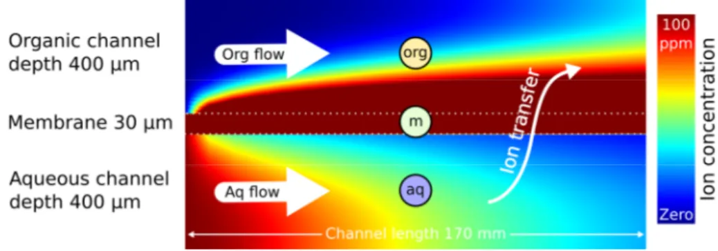
Figure 2: Sketch of a simulated concentration profiles in both microfluidic channels. The sketch is not to scale and the colour scale represents an example of ion distribution once a dynamic equilibrium is reached.
, respectively, and the equilibrium distribution coefficient according to the following expression:
= − / Equation 3
The chemical force is expressed as a gradient of chemical potential. Therefore, explicit calculations of effective flux require to express molar concentration in osmotic concentration (formerly called osmolarity). The corrections for activity between aqueous and organic phase need to be taken into account when considering a given process. In present conditions, the osmotic concentration correction is smaller than 10% [34], and is not considered in the following.
Initial conditions are Caq = 0 and Corg = 0. Furthermore, convection in both phases is calculated by the flow rate, Q, generated by the syringe pumps. This defines the
incoming solute flux in the aqueous channel, i.e. the feed phase, = =
100 ∙ , where Q = 0.16 mm2 · L/tcont with the desired residence time, tcont, of solute in the extraction section of length L = 170 mm. The extraction phase is exempt of ions,
hence = 0 / .
The developed simulation uses a finite difference method to calculate the concentration profile throughout the domain [18]. The domain itself is tripartite: (a) the aqueous channel, (b) the porous membrane medium filled with organic phase and (c) the organic channel, as depicted in figure 2. In the latter figure, the simulated overall domain is split into three subdomains, (aq) aqueous channel with feed flow, 400 µm depth, (m) porous medium filled with organic liquid, 30 µm thickness, (org) organic channel, 400 µm depth. Solute extraction takes place for a contact length of 170 mm between (aq) and (org) through (m) in a coflow regime. The interface is thus situated between the aqueous phase and the hydrophobic membrane, inverse micelles build up directly at the interface inside the porous medium. Flow inside the porous medium is considered zero. Flow profiles in both channels are approximated by a 2D Poiseuille flow (flow between infinite parallel planes), instead of a more realistic 3D Poiseuille flow scenario, which would take into account the width of the channels. Even though, readers will see that simulation results compare well to experimental kinetics, which is why the authors did not question this simplification.
The three diffusion volume coefficients, one for each sub-domains, , !! =
∙ /" and Dorg, respectively, are fixed to the following values:
• Daq = 6 × 10⁻¹⁰ m2/s at 25°C [35];
• Dorg = 10−10 m2/s at 25°C, measured by Taylor dispersion analysis [36] by Moussa
Touré et al. [37] for Nd-HDEHP complexes in HDEHP 1M in dodecane, considering an inverse proportionality of viscosity (3.5 mPa s for HDEHP 1M and 1.61 mPa.s for TODGA 0.1 M and three dimers of HDEHP for one metal ion [38, 39] versus three monomers of TODGA for one metal ion [40] as complexes which diffuses in the organic phase. The molar mass of those entities is comparable and
extrapolated to the present work taking into account the difference of viscosity of the two systems;
• !! = ∙ /" = 2.75 × 10()) */ at 25°C, using p = 0.55 and τ = 2.
Temperature dependence of diffusivity is given by the Einstein-Stokes theorem, D(T) =
D(25°C) · T/25°C, for T = 19°C and T = 35°C, counted in Kelvin scale, respectively for the
two data sets described below. The distribution coefficient at thermodynamic equilibrium:
= / , Equation 4
is determined experimentally using batch experiments. It is then reinjected into the simulation for each pair of feed and extraction phase to determine solute flux magnitude. The diffusivities, convection rates and distribution coefficients being known. Hence, the only adjustable parameter n the simulation is the solute transfer rate at the liquid-liquid interface, kv. There resides our interest in the microsystem since this parameter is difficult to measure using classic methods of extraction. The kinetics
measurement in microfluidics allows a good estimate for kv as will be pointed out in the
results and discussion section.
2.2MODEL OF SOLUTE TRANSPORT
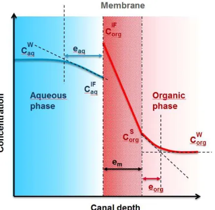
The concentration profile for each channel and the membrane is linearized: a constant and a linear profile in both liquid channels, and a linear profile in the membrane. This allows estimation of linear gradient widths, eaq and eorg (figure 3). These gradient widths are related to the diffusive resistances, R = ρ e, in each domain and through the interface. The resistance is the product of gradient width e and diffusive resistivity ρ =
Figure 3: sketch representing the various gradient considered and their linear approximation.
Overall, the calculated concentration profiles can be approximated by linear gradients to refer to the classical model of liquid-liquid pertraction [41]. These linear gradients help to consider approximate diffusive resistance for each domain. An estimation of the thickness of the diffusion layer in both phases can be also calculated.
This is a way of calculating respective contributions to diffusive resistances and obtain an estimation of the major barrier throughout the extraction process. Classically [42],
the transfer flux, , , + ,-. , can be expressed for each gradient domain,
aqueous, interface, membrane and organic, respectively, as follow: = /01 01 2 − = 2− Equation 5 = − / Equation 6 + =3/456 78 − 9 Equation 7 = /456 456 9 − 2 = 9 − 2 Equation 8
: : = ; 2− 2 / Equation 9
With the calculated concentration profiles, it is possible to determine the thickness of the organic and aqueous diffusion layers on each side of the membrane, as well as the local transfer coefficients kaq = Daq/eaq and korg = Dorg/eorg, without using correlation laws. The total transfer coefficient, K, can be written in combination with total solute flux, . As there is no accumulation of matter at the interface, the transfer fluxes expressed in
each domain and for the overall system are equal at dynamic equilibrium: = IF = m =
org = tot.
From above equations, the total transfer resistance as written from the aqueous side reference, Rtot, can then be written as a serial contribution of the single resistances: <: : ==) =>) 01+ ) >@3+ 78 >A3/456+ ) >A>456 Equation 10
Please note that the whole mathematical formalism can as well be written with the organic phase as reference, which yields the same results up to a factor kd.
3
RESULTS AND DISCUSSION
0 0.2 0.4 0.6 0.8 1 0 0.2 0.4 0.6 0.8 1 A B pH 2.3 pH 1.0
Aqueous Interface Membrane Organic phase
Figure 4: Extraction kinetics, dependence on pH at 19°C.
Dependence of extraction kinetics on pH at 19°C is shown in figure 4. It shows that high acidity yields high extraction efficiency, low acidity yields high inter-lanthanide selectivity. Iron as control has poor kd. Overall kinetics significantly accelerates as pH is reduced. This is classically attributed to some apparent stoichiometry of a complex including some adducts [43].
However, the driving force in the non-equilibrium systems is the chemical potential difference of the electrolyte between the initial location of the ion in water phase and the final location in the organic solvent phase [44]. In the case of HDEHP, we are dealing with the “case Type III-B: Extraction of saturated metal complex” including adducts in the general classification of metal selective extraction that includes seventeen categories for which no general predictive theory is established yet.
When a neutral saturated metal complex forming in the organic phase has been considered as the conjunction of driving forces and quenching mechanisms, the large difference between metal complexation free energy and the global extraction free energy can be identified as a combination of bulk “entropic” electrostatic terms and other minor terms [45].
It is also noticed that at higher pH, higher mass (smaller ionic radii) lanthanides are
more extracted (kd is higher) than smaller lanthanides. This derives from the quenching
term related to the complexing agent reorganisation around the cation to be extracted [46]. However, a quantitative evaluation requires to abandon the concept of average stoichiometry and consider a Boltzmann distribution of complexing aggregates in dynamic equilibrium [47]. Since, the selectivity also depends on pH, it also shows the impact of interfacial curvature frustration that depends on the total volume of all the hydrophilic extracted species in each aggregate [48, 49].
It should also be noted that when pH changes, the solution’s ionic strength also changes. TODGA however belongs to the class of solvating extractants: their efficiency is not linked to a cation exchange.[44] Therefore the extraction efficiency is limited by the necessity to keep the nitrate counter-ions in the reverse micelle formed in the solvent phase. This is industrially done by adjusting the pH to a low value (pH lower than one).
However, if pH is too low, it induces the co-extraction of large quantities of water, which limits the selectivity versus iron.[50]
These known trends are all found in results presented in figure 4: iron is not extracted. When quenching mechanisms are in minority, all amounts for all dissolved lanthanide ions are extracted. When there is a balance between complexation and phase transfer quenching effects, smaller/heavier lanthanide ions are less extracted than the larger/lighter ones, depending on the solvent used [51]. This is also the case for synergic extraction when two extractants are used in a specific ratio [52, 53].
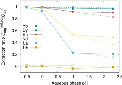
Figure 5: The liquid-liquid extraction ratio was measured as a function of pH via two methods: (i) using the miniaturized membrane, microfluidic, device described in this article (solid line, full symbols) and classical batch experiments in sample tubes (dashed lines, open symbols), at 19°C.
A comparison of the data acquired both using our microfluidic device and in batch samples is presented in figure 5 and then analysed. For all cations present in solution both data set coincide within experimental uncertainty of the analysis.
Table 1 : Experimental distribution coefficients kd of the five lanthanide elements at the four experimental pH (19°C)
Moreover, on figure 6, selectivity appears to be dependent on temperature. In classical view of extraction, this is a surprising observation, corresponding to an apparent entropic term in the free energy linked to structural reorganisation of the solvent phase upon complexation. However, once complexation, bulk and electrostatic free energy terms are identified [50], it is clear that this term is related to entropy of the complexing molecules, that participate to a highly bent interfacial film [54].
Figure 6: The system was studied at two different temperatures, 19°C and 35°C, pH 2.3
using both microfluidic, (full symbols). Fitted data using our simulation approach are represented in dashed lines.
The fitted simulation curves for 19°C using parameter kv show that light rare earth
ions (La3+, Nd3+, Eu3+) extraction kinetics can easily be fitted simply by adjusting kv. Hence for these elements, kinetics follow a mixed diffusive-reactive regime. For heavier rare earth ions, such as Dy3+ and Yb3+, at pH=2.3 one can observed a misfit between experimental and calculated values for contact times bellow 10 min. This points out a
pure diffusive regime for these elements. The kv values used for the fits are summarized
Transfer coefficient kv (10−7 m/s) Temperature 19°C 35°C La3+ 30 50 Nd3+ 30 20 Eu3+ 250 60 Dy3+ N.A. 250 Yb3+ N.A. 200
Table 2: Transfer rate kv values used for adjusting simulated to experimental curves at
pH 2.3 for mixed diffusive-reactive regimes. Data for pure diffusive regimes could not be obtained since the transfer rate does not participate in kinetics (values assigned: N.A.).
Resistance chart
A resistance chart according to the later equation is proposed in table 3. Resistances were determined as a function of both variables kd and kv, in the limits of 0.5 to 1000 and 10−4 to 3 × 10⁻⁶ m/s, respectively, for two contact times (tcont): (i) tcont = 2 min 45 s with both aqueous and organic injection flow rates identical (coflow), Qaq = Qorg = 10 µL/min, respectively and (ii) tcont = 39 min in two regimes, either in coflow, Qaq = Qorg = 0.7 µL/min, two special conditions were calculated with a very high aqueous flow rate (Qaq = 1000 µL/min; Qorg = 0.7 µL/min; Qaq/Qorg = 1430) or with a high organic flowrate (Qaq = 0.7 µL/min; Qorg = 1000 µL/min; Qaq/Qorg = 7x10⁻⁴) in order to show the influence of high flow rate on resistance contributions. Diffusive resistance is calculated using a panoply of distribution coefficients, kd, reaching from less efficient extraction, kd = 0.5, to excellent extraction, kd = 1000. These values are then examined for different interface transfer rates, kv = 3 × 10⁻⁶ m/s to 10−4 m/s, i.e. from slow to fast interface transfer. Simulations are also evaluated at short and long contact time, in order to determine whether diffusive resistance changed significantly over time.
Detailed results are given in table 3 in terms of relative diffusive resistances. They show several tendencies. First, for low org/aq distribution coefficients, which means a low chemical potential difference during the transfer from the aqueous phase, the main diffusive resistance is located in the organic phase. High organic flow rate leads to a lower resistance contribution of the organic phase due to the reduction of the diffusion
A second tendency can be observed regarding the influence of interface transfer. For low kv, interface transfer is slow, and the major resistance contributor shifts to the interface domain.
Aqueous Interface Membrane Organic 1000 1.00E-04 Qaq=1000, Qorg= 0.7 81.6 15.7 0.942 1.78 1000 1.00E-04 0.7 93.5 4.51 0.27 1.73 1000 1.00E-05 0.7 65.9 33.2 0.199 0.712 1000 3.00E-06 0.7 36.3 63.4 0.114 0.277 1000 1.00E-04 10 94.7 4.61 0.277 0.428 1000 1.00E-05 10 65.8 33.7 0.202 0.282 1000 3.00E-06 10 35.8 63.9 0.115 0.148 100 1.00E-04 0.7 80.3 4.03 2.42 13.2 100 1.00E-05 0.7 60.9 30.9 1.86 6.34 100 3.00E-06 0.7 35 61.3 1.1 2.66 100 1.00E-04 10 88.8 4.46 2.68 4.1 100 1.00E-05 10 62.9 32.5 1.95 2.71 100 3.00E-06 10 34.9 62.5 1.12 1.45 30 1.00E-04 0.7 61.7 3.34 6.68 28.3 30 1.00E-05 0.7 51.4 26.7 5.33 16.7 30 3.00E-06 0.7 32.1 56.5 3.39 8.05 30 1.00E-04 10 75.6 4.07 8.14 12.2 30 1.00E-05 10 56.4 29.6 5.91 8.16 30 3.00E-06 10 32.9 59 3.54 4.56 10 1.00E-04 0.7 38.4 2.4 14.4 44.7 10 1.00E-05 0.7 36.3 19.7 11.8 32.1 10 3.00E-06 0.7 26 46.4 8.36 19.2 10 1.00E-04 10 50.9 3.14 18.9 27.1 10 1.00E-05 10 43.2 23.5 14.1 19.2 10 3.00E-06 10 28.1 50.9 9.17 11.8 5 1.00E-04 0.7 24.2 1.71 20.5 53.7 5 1.00E-05 0.7 25.3 14.5 17.4 42.8 5 3.00E-06 0.7 20.2 36.9 13.3 29.6 5 1.00E-04 10 32.6 2.27 27.2 37.9 5 1.00E-05 10 31.4 18 21.6 29.1 5 3.00E-06 10 22.9 42.2 15.2 19.6 2 1.00E-04 0.7 10.9 0.901 27 61.2 2 1.00E-05 0.7 12.8 8.18 24.6 54.4 2 3.00E-06 0.7 12 23 20.7 44.2 2 1.00E-04 10 14.6 1.19 35.8 48.3 2 1.00E-05 10 16.5 10.5 31.4 41.7 2 3.00E-06 10 14.5 27.9 25.1 32.5 2 3.00E-06 Qa q=0.7, Qorg=1000 18.7 35.8 32.2 13.3 0.5 1.00E-04 0.7 2.77 0.264 31.7 65.3 0.5 1.00E-05 0.7 3.23 2.57 30.9 63.3 0.5 3.00E-06 0.7 3.63 8.08 29.1 59.2 0.5 1.00E-04 10 3.65 0.346 41.5 54.5 0.5 1.00E-05 10 4.23 3.33 40 52.4 0.5 3.00E-06 10 4.65 10.3 37 48.1
Distribution coefficient k
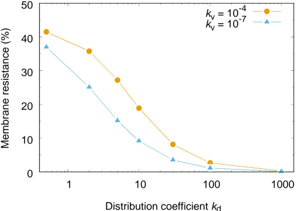
dFigure 7: Percentage of membrane resistance to overall resistance at high reaction rate,
kv = 10−7, and low reaction rate, kv = 10−10.
The final point regards the membrane resistance, which is mostly important for low distribution coefficients. Then, the concentration gradient in the adjacent organic phase is low, and the membrane accumulates extraction aggregates. This point is further illustrated in figure 7. Data is plotted for equal coflow in both channels, Qaq = Qorg = 10
µL/min, which corresponds to a contact time of 2’45”. A short contact time is chosen to
illustrate the functioning far from thermodynamic equilibrium. However, note that
dynamic equilibrium is well attained for the complete data set. The percentage of
membrane resistance is plotted as a function of distribution coefficient kd. The significant fall of membrane resistance for high kd is demonstrated. Hence, in order to operate an efficient process, distribution coefficients should be at least kd > 10 or higher, signifying a low impact from membrane diffusive resistance.
0
10
20
30
40
50
1
10
100
1000
M
em
brane
re
s
is
tan
c
e
(%)
k
v= 10
-4k
v= 10
-74
CONCLUSION AND OUTLOOK
In this work, a microfluidic device based on pertraction principles was presented, studied and validated using a industrially relevant model case in hydrometallurgy (ca. the role of pH in rare earth extraction, using TODGA as an extracting molecule). The device not only reproduces, within measurement error bars, batch experiments used as benchmark, It also gave kinetics pieces of information. At 19°C, extraction and kinetics dependence on pH was examined. For pH 2.3, two different temperatures were analysed.
A simple diffusion-reaction model was proposed and diffusive resistances of the four barriers, i.e. feed channel, interface, porous medium and extraction channel, were evaluated. The methodical analysis of these diffusive resistances given by the developed model shows that the presence of the thin membrane does not perturb the equilibrium nor does it increases significantly the time of experiment. Hence it makes the determination of process selectivity by membrane based, pertraction microfluidics an easier and more deployable approach than ones based on circulating alternating oil and water droplets [56]. However, in the latter method, the determination of kinetics may be more precise since the global flux through the device can be varied more easily and on a larger range.
It should be noted that these conclusions are just as valid for desextraction, since the important parameter governing diffusive resistance in different domains is the relative level of chemical potential. For desextraction, chemical potentials are interverted and so is diffusive resistance. Again, for high kD, as supposed for efficient extraction processes, the membrane resistance stays below 20%.
Another outcome is that when designing pertraction microfluidic device, an important design rule should be to reduce channels depth in order to speed up bulk diffusion, or to implement additional convection methods. Toward that end, some research is needed to regulate or speed up interface transfer through e.g. ultrasound [25, 57] or electric means [58], [59].
Finally, the feasibility to implement on-line analytical devices (FTIR) on milli-fluidic chip has been successfully demonstrated [21, 60]. Primary results suggest the possibility to have a fast and precise screening of several physico-chemical parameters. It should enable to analyse qualitatively and quantitatively extraction performances of
CEA/DRT/LETI for help with microfluidics manufacturing. The in depth and detailed report of one reviewer is also acknowledged.
FUNDING SOURCES
Researchleading to these results was performed at CEA and received funding from the
European Research Council under the European Union’s 7th Framework Program
(FP/2007-2013)/ERC Grant Agreement N◦ [320915] “REE-CYCLE”: Rare Earth Element
reCYCling with Low harmful Emissions. Financial support from SCARCE joint NTU/CEA laboratory for JCG, while staying at Nanyang Technological University in Singapore, enabled the final writing stages of this article. SCARCE is supported by the National Research Foundation, Prime Minister’s Office, Singapore, the Ministry of National Development, Singapore, and National Environment Agency, Ministry of the Environment and Water Resource, Singapore under the Closing the Waste Loop R&D Initiative as part of the Urban Solutions & Sustainability – Integration Fund (Award No. USS-IF-2018-4).
Declarations of interest: none.
REFERENCES
[1] T. Luo, S. Abdu, M. Wessling, Selectivity of ion exchange membranes: A review, J. Membr. Sci., 555 (2018) 429-454.
[2] H. Estay, E. Troncoso, R. Ruby-Figueroa, J. Romero, Performance evaluation of mass transfer correlations in the GFMA process: A review with perspectives to the design, J. Membr. Sci., 554 (2018) 140-155.
[3] C.F. Wan, T.S. Yang, G.G. Lipscomb, D.J. Stookey, T.S. Chung, Design and fabrication of hollow fiber membrane modules, J. Membr. Sci., 538 (2017) 96-107.
[4] J. Ran, L. Wu, Y.B. He, Z.J. Yang, Y.M. Wang, C.X. Jiang, L. Ge, E. Bakangura, T.W. Xu, Ion exchange membranes: New developments and applications, J. Membr. Sci., 522 (2017) 267-291.
[5] E. Chabanon, D. Mangin, C. Charcosset, Membranes and crystallization processes: State of the art and prospects, J. Membr. Sci., 509 (2016) 57-67. [6] Y. Wibisono, E.R. Cornelissen, A.J.B. Kemperman, W.G.J. van der Meer, K. Nijmeijer, Two-phase flow in membrane processes: A technology with a future, J. Membr. Sci., 453 (2014) 566-602.
[7] N.B. McKeown, P.M. Budd, Polymers of intrinsic microporosity (PIMs): organic materials for membrane separations, heterogeneous catalysis and hydrogen storage, Chem. Soc. Rev., 35 (2006) 675-683.
[8] C. Sanchez, B. Julian, P. Belleville, M. Popall, Applications of hybrid organic-inorganic nanocomposites, J. Mater. Chem., 15 (2005) 3559-3592.
[9] J.C.P. Gabriel, 2d Random networks of carbon nanotubes, Comptes Rendus Physique, 11 (2010) 362-374.
[10] C. Phillips, M. Jakusch, H. Steiner, B. Mizaikoff, A.G. Fedorov, Model-based optimal design of polymer-coated chemical sensors, Analytical Chemistry, 75 (2003) 1106-1115.
[11] J. Arcamone, A. Niel, V. Gouttenoire, M. Petitjean, N. David, R. Barattin, M. Matheron, F. Ricoul, T. Bordy, H. Blanc, J. Ruellan, D. Mercier, N. Pereira-Rodrigues, G. Costa, V. Agache, S. Hentz, J.C. Gabriel, F. Baleras, C. Marcoux, T. Ernst, L. Duraffourg, E. Colinet, E.B. Myers, M.L. Roukes, P. Andreucci, E. Ollier, P. Puget, Ieee, VLSI silicon multi-gas analyzer coupling gas chromatography and NEMS detectors, 2011.
[12] P. Bernardo, E. Drioli, G. Golemme, Membrane Gas Separation: A Review/State of the Art, Industrial & Engineering Chemistry Research, 48 (2009) 4638-4663.
[13] E. Bringas, M.F.S. Roman, J.A. Irabien, I. Ortiz, An overview of the mathematical modelling of liquid membrane separation processes in hollow fibre contactors, J. Chem. Technol. Biotechnol., 84 (2009) 1583-1614.
[14] I. Diaconu, E. Ruse, H.Y. Aboul-Enein, A.A. Bunaciu, Analytical Applications of Transport Through Bulk Liquid Membranes, Critical Reviews in Analytical Chemistry, 46 (2016) 332-341.
[15] A.J.B. Kemperman, D. Bargeman, T. vandenBoomgaard, H. Strathmann, Stability of supported liquid membranes: State of the art, Separation Science and Technology, 31 (1996) 2733-2762.
[16] A.M. Sastre, A. Kumar, J.P. Shukla, R.K. Singh, Improved techniques in liquid membrane separations: An overview, Separation and Purification Methods, 27 (1998) 213-298.
[17] J. Berthier, V.M. Tran, F. Mittler, N. Sarrut, The physics of a coflow micro-extractor: Interface stability and optimal extraction length, Sensors and Actuators a-Physical, 149 (2009) 56-64.
[18] A. Aota, A. Hibara, T. Kitamori, Pressure balance at the liquid-liquid interface of micro countercurrent flows in microchips, Analytical Chemistry, 79 (2007) 3919-3924.
[19] C. Xu, T.L. Xie, Review of Microfluidic Liquid-Liquid Extractors, Industrial & Engineering Chemistry Research, 56 (2017) 7593-7622.
[20] P. Grathwohl, Diffusion in natural porous media: Contaminant transport, sorption / desorption and dissolution kinetics, 1 ed., Springer US, New York,
[24] A. Vansteene, J.P. Jasmin, G. Cote, C. Mariet, Segmented Microflows as a Tool for Optimization of Mass Transfer in Liquid-Liquid Extraction: Application at the Extraction of Europium(III) by a Malonamide, Industrial & Engineering Chemistry Research, 57 (2018) 11572-11582.
[25] J. Duhamet, H. Mohwald, M. Pleines, T. Zemb, Self-Regulated Ion Permeation through Extraction Membranes, Langmuir, 33 (2017) 9873-9879.
[26] T. Huynh, B. Sun, L. Li, K.P. Nichols, J.L. Koyner, R.F. Ismagilov, Chemical Analog-to-Digital Signal Conversion Based on Robust Threshold Chemistry and Its Evaluation in the Context of Microfluidics-Based Quantitative Assays, Journal of the American Chemical Society, 135 (2013) 14775-14783.
[27] S. Tachimori, Y. Sasaki, S. Suzuki, Modification of TODGA-n-dodecane solvent with a monoamide for high loading of lanthanides(III) and actinides(III), Solvent Extraction and Ion Exchange, 20 (2002) 687-699.
[28] S.A. Ansari, P.K. Mohapatra, A review on solid phase extraction of actinides and lanthanides with amide based extractants, Journal of Chromatography A, 1499 (2017) 1-20.
[29] M. Gergoric, A. Barrier, T. Retegan, Recovery of Rare-Earth Elements from Neodymium Magnet Waste Using Glycolic, Maleic, and Ascorbic Acids Followed by Solvent Extraction, Journal of Sustainable Metallurgy, 5 (2019) 85-96.
[30] M.P. Jensen, T. Yaita, R. Chiarizia, Reverse-micelle formation in the partitioning of trivalent f-element cations by biphasic systems containing a tetraalkyldiglycolamide, Langmuir, 23 (2007) 4765-4774.
[31] M. Corti, A. Raudino, L. Cantu’, J. Theisen, M. Pleines, T. Zemb, Nanometric Surface Oscillation Spectroscopy of Water-Poor Microemulsions, Langmuir, 34 (2018) 8154-8162.
[32] K. Binnemans, P.T. Jones, B. Blanpain, T. Van Gerven, Y. Yang, A. Walton, M. Buchert, Recycling of rare earths: a critical review, Journal of Cleaner Production, 51 (2013) 1-22.
[33] J. Crank, E.P.J. Crank, The Mathematics of Diffusion, Clarendon Press, 1979. [34] K.G. Weil, V. M. M. Lobo: Physical Sciences Data 41. Handbook of Electrolyte Solutions, Part A,. V. M. M. Lobo, J. L. Quaresma: Physical Sciences Data 41. Handbook of Electrolyte Solutions, Part B, ISBN Vol. 41: 0-444-98847-5, Elsevier Amsterdam, Oxford, New York, Tokyo 1989, 2354 Seiten, Preis: Dfl. 1.400, –, Berichte der Bunsengesellschaft für physikalische Chemie, 95 (1991) 1305-1305.
[35] N. Ouerfelli, H. Latrous, M. Ammar, An equation for self-diffusion coefficients of the trivalent lanthanide ion Eu-152 (III) in concentrated asymmetrical 3:1 electrolyte aqueous solutions at pH 2.50 and at 298.15 K, J. Mol. Liq., 146 (2009) 52-59.
[36] J. Chamieh, F. Oukacine, H. Cottet, Taylor dispersion analysis with two detection points on a commercial capillary electrophoresis apparatus, Journal of Chromatography A, 1235 (2012) 174-177.
[37] M. Touré, Étude des conditions de mise en œuvre de la pertraction pour l’extraction et la purification des métaux d’intérêt., in, Université de Montpellier, 2015.
[38] Z. Kolarik, H. Pankova, acidic organophosphorus extractants .i. Extraction of lanthanides by means of dialkyl phosphoric acids - effect of structure and size of alkyl group, Journal of Inorganic & Nuclear Chemistry, 28 (1966) 2325-&.
[39] M.R. Antonio, R. Chiarizia, B. Gannaz, L. Berthon, N. Zorz, C. Hill, G. Cote, Aggregation in solvent extraction systems containing a malonamide, a dialkylphosphoric acid and their mixtures, Separation Science and Technology, 43 (2008) 2572-2605.
[40] M. Arisaka, T. Kimura, Thermodynamic and Spectroscopic Studies on Am(III) and Eu(III) in the Extraction System of N,N,N ',N '-Tetraoctyl-3-Oxapentane-1,5-Diamide in n-Dodecane/Nitric Acid, Solvent Extraction and Ion Exchange, 29 (2011) 72-85.
[41] I. Ortiz, B. Galan, F. San Roman, R. Ibanez, Kinetics of separating multicomponent mixtures by nondispersive solvent extraction: Ni and Cd, Aiche Journal, 47 (2001) 895-905.
[42] A. Gabelman, S.T. Hwang, Hollow fiber membrane contactors, J. Membr. Sci., 159 (1999) 61-106.
[43] J. Rydberg, Solvent Extraction Principles and Practice, Revised and Expanded, Taylor & Francis, 2004.
[44] T. Zemb, C. Bauer, P. Bauduin, L. Belloni, C. Dejugnat, O. Diat, V. Dubois, J.F. Dufreche, S. Dourdain, M. Duvail, C. Larpent, F. Testard, S. Pellet-Rostaing, Recycling metals by controlled transfer of ionic species between complex fluids: en route to "ienaics", Colloid and Polymer Science, 293 (2015) 1-22.
[45] J.F. Dufreche, T. Zemb, Effect of long-range interactions on ion equilibria in liquid-liquid extraction, Chem. Phys. Lett., 622 (2015) 45-49.
[46] M. Bley, B. Siboulet, A. Karmakar, T. Zemb, J.F. Dufreche, A predictive model of reverse micelles solubilizing water for solvent extraction, Journal of Colloid and Interface Science, 479 (2016) 106-114.
[47] Y.S. Chen, M. Duvail, P. Guilbaud, J.F. Dufreche, Stability of reverse micelles in rare-earth separation: a chemical model based on a molecular approach, Physical Chemistry Chemical Physics, 19 (2017) 7094-7100.
[48] P. Guilbaud, T. Zemb, Depletion of water-in-oil aggregates from poor solvents: Transition from weak aggregates towards reverse micelles, Current Opinion in Colloid & Interface Science, 20 (2015) 71-77.
[49] A. Karmakar, M. Duvail, M. Bley, T. Zemb, J.F. Dufreche, Combined supramolecular and mesoscale modelling of liquid-liquid extraction of rare earth salts, Colloids and Surfaces a-Physicochemical and Engineering Aspects,
[53] J. Rey, S. Dourdain, J.F. Dufreche, L. Berthon, J.M. Muller, S. Pellet-Rostaing, T. Zemb, Thermodynamic Description of Synergy in Solvent Extraction: I. Enthalpy of Mixing at the Origin of Synergistic Aggregation, Langmuir, 32 (2016) 13095-13105.
[54] M. Duvail, L. Arleth, T. Zemb, J.F. Dufreche, Predicting for thermodynamic instabilities in water/oil/surfactant microemulsions: A mesoscopic modelling approach, Journal of Chemical Physics, 140 (2014).
[55] P.M. Gassin, R. Champory, G. Martin-Gassin, J.F. Dufreche, O. Diat, Surfactant transfer across a water/oil interface: A diffusion/kinetics model for the interfacial tension evolution, Colloids and Surfaces a-Physicochemical and Engineering Aspects, 436 (2013) 1103-1110.
[56] K.P. Nichols, R.R. Pompano, L. Li, A.V. Gelis, R.F. Ismagilov, Toward Mechanistic Understanding of Nuclear Reprocessing Chemistries by Quantifying Lanthanide Solvent Extraction Kinetics via Microfluidics with Constant Interfacial Area and Rapid Mixing, Journal of the American Chemical Society, 133 (2011) 15721-15729.
[57] D. Radziuk, H. Mohwald, Ultrasonically treated liquid interfaces for progress in cleaning and separation processes, Physical Chemistry Chemical Physics, 18 (2016) 21-46.
[58] M. Chakraborty, Z.V.P. Murthy, C. Bhattacharya, S. Datta, Process intensification: Extraction of Chromium(VI) by Emulsion Liquid Membrane, Separation Science and Technology, 40 (2005) 2353-2364.
[59] M. Rezazadeh, Y. Yamini, S. Seidi, A. Esrafili, Pulsed electromembrane extraction: A new concept of electrically enhanced extraction, Journal of Chromatography A, 1262 (2012) 214-218.
[60] A.W. C. Penisson, J. Theisen, V. Kokoric, B. Mizaikoff, J.C.P. Gabriel, Water activity measurement of NaCl/H2O mixtures via substrate-integrated hollow waveguide infrared spectroscopy with integrated microfluidics, in: Nanotech 2018, CRC Press, Anaheim, CA, USA, 2018, pp. 198-201.
Aqueux Interphase Membrane Organique 1000 1.00E-04 Qaq 1000 et Qorg 0,7 81.6 15.7 0.942 1.78
1000 1.00E-04 0.7 93.5 4.51 0.27 1.73 1000 1.00E-05 0.7 65.9 33.2 0.199 0.712 1000 3.00E-06 0.7 36.3 63.4 0.114 0.277 1000 1.00E-04 10 94.7 4.61 0.277 0.428 1000 1.00E-05 10 65.8 33.7 0.202 0.282 1000 3.00E-06 10 35.8 63.9 0.115 0.148 100 1.00E-04 0.7 80.3 4.03 2.42 13.2 100 1.00E-05 0.7 60.9 30.9 1.86 6.34 100 3.00E-06 0.7 35 61.3 1.1 2.66 100 1.00E-04 10 88.8 4.46 2.68 4.1 100 1.00E-05 10 62.9 32.5 1.95 2.71 100 3.00E-06 10 34.9 62.5 1.12 1.45 30 1.00E-04 0.7 61.7 3.34 6.68 28.3 30 1.00E-05 0.7 51.4 26.7 5.33 16.7 30 3.00E-06 0.7 32.1 56.5 3.39 8.05 30 1.00E-04 10 75.6 4.07 8.14 12.2 30 1.00E-05 10 56.4 29.6 5.91 8.16 30 3.00E-06 10 32.9 59 3.54 4.56 10 1.00E-04 0.7 38.4 2.4 14.4 44.7 10 1.00E-05 0.7 36.3 19.7 11.8 32.1 10 3.00E-06 0.7 26 46.4 8.36 19.2 10 1.00E-04 10 50.9 3.14 18.9 27.1 10 1.00E-05 10 43.2 23.5 14.1 19.2 10 3.00E-06 10 28.1 50.9 9.17 11.8 5 1.00E-04 0.7 24.2 1.71 20.5 53.7 5 1.00E-05 0.7 25.3 14.5 17.4 42.8 5 3.00E-06 0.7 20.2 36.9 13.3 29.6 5 1.00E-04 10 32.6 2.27 27.2 37.9 5 1.00E-05 10 31.4 18 21.6 29.1 5 3.00E-06 10 22.9 42.2 15.2 19.6 2 1.00E-04 0.7 10.9 0.901 27 61.2 2 1.00E-05 0.7 12.8 8.18 24.6 54.4 2 3.00E-06 0.7 12 23 20.7 44.2 2 1.00E-04 10 14.6 1.19 35.8 48.3 2 1.00E-05 10 16.5 10.5 31.4 41.7 2 3.00E-06 10 14.5 27.9 25.1 32.5
2 3.00E-06 Qaq 0,7 et Qorg 1000 18.7 35.8 32.2 13.3
0.5 1.00E-04 0.7 2.77 0.264 31.7 65.3 0.5 1.00E-05 0.7 3.23 2.57 30.9 63.3 0.5 3.00E-06 0.7 3.63 8.08 29.1 59.2 0.5 1.00E-04 10 3.65 0.346 41.5 54.5 0.5 1.00E-05 10 4.23 3.33 40 52.4 0.5 3.00E-06 10 4.65 10.3 37 48.1
Aqueux Interphase Membrane Organique Rtot Qaq=Qorg (µL/min)
Résistance (%) Kd Kv (m/s)
Kd Kv Qaq Qorg (µL/min)
% Résistance
Note Experimentalement les coefficients de partage Kd ( rapport des concentrations phase organique/ phase aqueuse à l'équilibre) varient de 0,1 à plus de 1000. Quand le Kd est au dessus de 10 la résistance de la membrane n'est pas prépondérante. Dans la majorité des extractions réalisée les Kd sont supérieur à 10. La membrane n'y est donc pas limitante. La diffusion et le passage de l'interface sont alors limitants pour l'extraction liquide-liquide. La recherche de solutions pour augmenter la diffusion du milieu aqueux est en cours. L'augmentation du débit dans la phase limitante ne permet pas d'augmenter de façon significative la diffusion.
5 1.00E-04 10 32.6 2.27 27.2 37.9 4.01E+06 5 1.00E-05 10 31.4 18 21.6 29.1 5.06E+06 5 3.00E-06 10 22.9 42.2 15.2 19.6 7.18E+06 2 1.00E-04 0.7 10.9 0.901 27 61.2 4.04E+06 2 1.00E-05 0.7 12.8 8.18 24.6 54.4 4.44E+06 2 3.00E-06 0.7 12 23 20.7 44.2 5.26E+06 2 1.00E-04 10 14.6 1.19 35.8 48.3 3.04E+06 2 1.00E-05 10 16.5 10.5 31.4 41.7 3.48E+06 2 3.00E-06 10 14.5 27.9 25.1 32.5 4.35E+06
2 3.00E-06 Qaq 0,7 et Qorg 1000 18.7 35.8 32.2 13.3 3.39E+06 0.5 1.00E-04 0.7 2.77 0.264 31.7 65.3 3.44E+06 0.5 1.00E-05 0.7 3.23 2.57 30.9 63.3 3.53E+06 0.5 3.00E-06 0.7 3.63 8.08 29.1 59.2 3.75E+06 0.5 1.00E-04 10 3.65 0.346 41.5 54.5 2.63E+06 0.5 1.00E-05 10 4.23 3.33 40 52.4 2.73E+06 0.5 3.00E-06 10 4.65 10.3 37 48.1 2.95E+06
Aqueux Interphase Membrane Organique
1000 1.00E-04 Qaq=1000 et Qorg=0,7 81.9 15.7 0.629 1.78 1.16E+08
1000 1.00E-04 0.7 93.6 4.51 0.18 1.73 4.03E+08 1000 1.00E-05 0.7 65.9 33.2 0.133 7.13 5.47E+08 1000 3.00E-06 0.7 36.3 63.4 0.076 0.277 9.56E+08 1000 1.00E-04 10 94.8 4.61 0.185 0.428 3.94E+08 1000 1.00E-05 10 65.8 33.8 0.135 0.282 5.39E+08 1000 3.00E-06 10 35.8 64 0.0768 0.148 9.48E+08 100 1.00E-04 0.7 81 4.02 1.61 13.4 4.53E+07 100 1.00E-05 0.7 61.3 31.1 1.24 6.41 5.85E+07 100 3.00E-06 0.7 35.1 61.5 0.738 2.67 9.86E+07 100 1.00E-04 10 89.7 4.46 1.78 4.11 4.08E+07 100 1.00E-05 10 63.3 32.6 1.3 2.72 5.57E+07 100 3.00E-06 10 35.1 62.7 0.753 1.45 9.66E+07 30 1.00E-04 0.7 63.1 3.32 4.43 29.1 1.64E+07 30 1.00E-05 0.7 52.3 27 3.6 17.1 2.02E+07 30 3.00E-06 0.7 32.5 57.1 2.28 8.17 3.19E+07 30 1.00E-04 10 78.2 4.08 5.44 12.3 1.34E+07 30 1.00E-05 10 57.7 30 4 8.32 1.82E+07 30 3.00E-06 10 33.3 59.7 2.39 4.61 3.05E+07 10 1.00E-04 0.7 40.9 2.42 9.69 47 7.51E+06 10 1.00E-05 0.7 37.9 20.2 8.1 33.7 8.98E+06 10 3.00E-06 0.7 26.8 47.6 5.71 19.9 1.27E+07 10 1.00E-04 10 55.5 3.23 12.9 28.3 5.63E+06 10 1.00E-05 10 45.7 24.4 9.76 20.1 7.45E+06 10 3.00E-06 10 29.1 52.4 6.29 12.2 1.16E+07 5 1.00E-04 0.7 26.7 1.76 14.1 57.5 5.16E+06 5 1.00E-05 0.7 27.2 15.1 12.1 15.7 6.02E+06 5 3.00E-06 0.7 21.3 38.4 9.21 31.1 7.90E+06 5 1.00E-04 10 37.2 2.41 19.3 41.1 3.77E+06 5 1.00E-05 10 34.5 19.1 15.2 31.2 4.77E+06 5 3.00E-06 10 24.4 44.3 10.6 20.7 6.84E+06 2 1.00E-04 0.7 12.4 0.964 19.3 67.3 3.77E+06 2 1.00E-05 0.7 14.4 8.73 17.5 59.4 4.17E+06 2 3.00E-06 0.7 13.1 24.5 14.7 47.7 4.95E+06 2 1.00E-04 10 17.4 1.32 26.5 54.8 2.75E+06 2 1.00E-05 10 19.2 11.5 22.9 46.5 3.17E+06 2 3.00E-06 10 16.2 30.2 18.1 35.5 4.01E+06
2 3.00E-06 Qaq=0,7 et Qorg=1000 21.1 39.4 23.6 15.9 3.08E+06
0.5 1.00E-04 0.7 3.14 0.291 23.3 73.3 3.12E+06 0.5 1.00E-05 0.7 3.8 2.83 22.6 70.8 3.22E+06 0.5 3.00E-06 0.7 4.21 8.84 21.2 65.7 3.43E+06 0.5 1.00E-04 10 4.34 0.395 31.6 63.7 2.30E+06 0.5 1.00E-05 10 5.17 3.79 30.3 60.7 2.40E+06 0.5 3.00E-06 10 5.57 11.6 27.8 55 2.62E+06 Kd Kv (m/s) Qaq=Qorg (µL/min) Résistance (%)
30MICRONS 20 MICRONS
Aqueux InterphaMembraOrganiq Rtot Aqueux InterphaMembraOrganique Rtot
1000 1.00E-04 Qaq=1000 et Qorg=0,7 81.6 15.7 0 942 1.78 1.16E+08 1000 1.00E-04 Qaq=1000 et Qorg=0,7 81.9 15.7 0.629 1.78 1.16E+08
1000 1.00E-04 0.7 93.5 4.51 0.27 1.73 4.03E+08 1000 1.00E-04 0.7 93.6 4.51 0.18 1.73 4 03E+08
1000 1.00E-05 0.7 65.9 33.2 0.199 0.712 5.48E+08 1000 1.00E-05 0.7 65.9 33.2 0.133 7.13 5.47E+08
1000 3.00E-06 0.7 36.3 63.4 0.114 0.277 9.57E+08 1000 3.00E-06 0.7 36.3 63.4 0.076 0.277 9 56E+08
1000 1.00E-04 10 94.7 4.61 0 277 0.428 3.94E+08 1000 1.00E-04 10 94.8 4.61 0.185 0.428 3 94E+08
1000 1.00E-05 10 65.8 33.7 0 202 0.282 5.39E+08 1000 1.00E-05 10 65.8 33.8 0.135 0.282 5 39E+08
1000 3.00E-06 10 35.8 63.9 0.115 0.148 9.48E+08 1000 3.00E-06 10 35.8 64 0 0768 0.148 9.48E+08
100 1.00E-04 0.7 80.3 4.03 2.42 13.2 4.52E+07 100 1.00E-04 0.7 81 4.02 1.61 13.4 4 53E+07
100 1.00E-05 0.7 60.9 30.9 1.86 6.34 5.88E+07 100 1.00E-05 0.7 61.3 31.1 1.24 6.41 5 85E+07
100 3.00E-06 0.7 35 61.3 1.1 2.66 9.89E+07 100 3.00E-06 0.7 35.1 61.5 0.738 2.67 9 86E+07
100 1.00E-04 10 88.8 4.46 2.68 4.1 4.07E+07 100 1.00E-04 10 89.7 4.46 1.78 4.11 4 08E+07
100 1.00E-05 10 62.9 32.5 1.95 2.71 5.60E+07 100 1.00E-05 10 63.3 32.6 1.3 2.72 5 57E+07
100 3.00E-06 10 34.9 62.5 1.12 1.45 9.70E+07 100 3.00E-06 10 35.1 62.7 0.753 1.45 9.66E+07
30 1.00E-04 0.7 61.7 3.34 6.68 28.3 1.63E+07 30 1.00E-04 0.7 63.1 3.32 4.43 29.1 1.64E+07
30 1.00E-05 0.7 51.4 26.7 5.33 16.7 2.05E+07 30 1.00E-05 0.7 52.3 27 3.6 17.1 2 02E+07
30 3.00E-06 0.7 32.1 56.5 3.39 8.05 3.22E+07 30 3.00E-06 0.7 32.5 57.1 2.28 8.17 3.19E+07
30 1.00E-04 10 75.6 4.07 8.14 12.2 1.34E+07 30 1.00E-04 10 78.2 4.08 5.44 12.3 1 34E+07
30 1.00E-05 10 56.4 29.6 5.91 8.16 1.85E+07 30 1.00E-05 10 57.7 30 4 8.32 1 82E+07
30 3.00E-06 10 32.9 59 3.54 4.56 3.08E+07 30 3.00E-06 10 33.3 59.7 2.39 4.61 3 05E+07
10 1.00E-04 0.7 38.4 2.4 14.4 44.7 7.57E+06 10 1.00E-04 0.7 40.9 2.42 9.69 47 7 51E+06
10 1.00E-05 0.7 36.3 19.7 11.8 32.1 9.21E+06 10 1.00E-05 0.7 37.9 20.2 8.1 33.7 8 98E+06
10 3.00E-06 0.7 26 46.4 8.36 19.2 1.30E+07 10 3.00E-06 0.7 26.8 47.6 5.71 19.9 1 27E+07
10 1.00E-04 10 50.9 3.14 18.9 27.1 5.78E+06 10 1.00E-04 10 55.5 3.23 12.9 28.3 5.63E+06
10 1.00E-05 10 43.2 23.5 14.1 19.2 7.73E+06 10 1.00E-05 10 45.7 24.4 9.76 20.1 7.45E+06
10 3.00E-06 10 28.1 50.9 9.17 11.8 1.19E+07 10 3.00E-06 10 29.1 52.4 6.29 12.2 1.16E+07
5 1.00E-04 0.7 24.2 1.71 20.5 53.7 5.33E+06 5 1.00E-04 0.7 26.7 1.76 14.1 57.5 5.16E+06
5 1.00E-05 0.7 25.3 14.5 17.4 42.8 6.27E+06 5 1.00E-05 0.7 27.2 15.1 12.1 15.7 6 02E+06
5 3.00E-06 0.7 20.2 36.9 13.3 29.6 8.24E+06 5 3.00E-06 0.7 21.3 38.4 9.21 31.1 7 90E+06
5 1.00E-04 10 32.6 2.27 27.2 37.9 4.01E+06 5 1.00E-04 10 37.2 2.41 19.3 41.1 3.77E+06
5 1.00E-05 10 31.4 18 21.6 29.1 5.06E+06 5 1.00E-05 10 34.5 19.1 15.2 31.2 4.77E+06
5 3.00E-06 10 22.9 42.2 15.2 19.6 7.18E+06 5 3.00E-06 10 24.4 44.3 10.6 20.7 6 84E+06
2 1.00E-04 0.7 10.9 0.901 27 61.2 4.04E+06 2 1.00E-04 0.7 12.4 0.964 19.3 67.3 3.77E+06
2 1.00E-05 0.7 12.8 8.18 24.6 54.4 4.44E+06 2 1.00E-05 0.7 14.4 8.73 17.5 59.4 4.17E+06
2 3.00E-06 0.7 12 23 20.7 44.2 5.26E+06 2 3.00E-06 0.7 13.1 24.5 14.7 47.7 4 95E+06
Kv (m/s)Qaq=Qorg (µL m n)
Résistance (%) Kd Kv (m/s)Qaq=Qorg (µL m n)
Résistance (%)
2 3.00E-06 Qaq=0,7 et Qorg=100 0 18.7 35.8 32.2 13.3 3.39E+06 2 3.00E-06 Qaq=0,7 et Qorg=100 0 21.1 39.4 23.6 15.9 3 08E+06
0.5 1.00E-04 0.7 2.77 0.264 31.7 65.3 3.44E+06 0.5 1.00E-04 0.7 3.14 0.291 23.3 73.3 3.12E+06
0.5 1.00E-05 0.7 3.23 2.57 30.9 63.3 3.53E+06 0.5 1.00E-05 0.7 3.8 2.83 22.6 70.8 3 22E+06
0.5 3.00E-06 0.7 3.63 8.08 29.1 59.2 3.75E+06 0.5 3.00E-06 0.7 4.21 8.84 21.2 65.7 3.43E+06
0.5 1.00E-04 10 3.65 0.346 41.5 54.5 2.63E+06 0.5 1.00E-04 10 4.34 0.395 31.6 63.7 2 30E+06
0.5 1.00E-05 10 4.23 3.33 40 52.4 2.73E+06 0.5 1.00E-05 10 5.17 3.79 30.3 60.7 2.40E+06
Aqueous Interface Membrane Organic 1000 1.00E-04 Qaq1000, Qo g 0.7 81.6 15.7 0.942 1.78
1000 1.00E-04 0.7 93.5 4.51 0.27 1.73 Membrane : Porosité 0,55
1000 1.00E-05 0.7 65.9 33.2 0.199 0.712 Tortuosité 2
1000 3.00E-06 0.7 36.3 63.4 0.114 0.277 Epaisseur 20 µm
1000 1.00E-04 10 94.7 4.61 0.277 0.428
1000 1.00E-05 10 65.8 33.7 0.202 0.282
1000 3.00E-06 10 35.8 63.9 0.115 0.148 Aqueux Interphase Membrane Organique Rtot
100 1.00E-04 0.7 80.3 4.03 2.42 13.2 1000 1.00E-04 Qaq 1000 et Qorg 0,7 81.9 15.7 0.629 1.78 1.16E 08
100 1.00E-05 0.7 60.9 30.9 1.86 6.34 1000 1.00E-04 0.7 93.6 4.51 0.18 1.73 4.03E 08
100 3.00E-06 0.7 35 61.3 1.1 2.66 1000 1.00E-05 0.7 65.9 33.2 0.133 7.13 5.47E 08
100 1.00E-04 10 88.8 4.46 2.68 4.1 1000 3.00E-06 0.7 36.3 63.4 0.076 0.277 9.56E 08
100 1.00E-05 10 62.9 32.5 1.95 2.71 1000 1.00E-04 10 94.8 4.61 0.185 0.428 3.94E 08
100 3.00E-06 10 34.9 62.5 1.12 1.45 1000 1.00E-05 10 65.8 33.8 0.135 0.282 5.39E 08
30 1.00E-04 0.7 61.7 3.34 6.68 28.3 1000 3.00E-06 10 35.8 64 0.0768 0.148 9.48E 08
30 1.00E-05 0.7 51.4 26.7 5.33 16.7 100 1.00E-04 0.7 81 4.02 1.61 13.4 4.53E 07
30 3.00E-06 0.7 32.1 56.5 3.39 8.05 100 1.00E-05 0.7 61.3 31.1 1.24 6.41 5.85E 07
30 1.00E-04 10 75.6 4.07 8.14 12.2 100 3.00E-06 0.7 35.1 61.5 0.738 2.67 9.86E 07
30 1.00E-05 10 56.4 29.6 5.91 8.16 100 1.00E-04 10 89.7 4.46 1.78 4.11 4.08E 07
30 3.00E-06 10 32.9 59 3.54 4.56 100 1.00E-05 10 63.3 32.6 1.3 2.72 5.57E 07
10 1.00E-04 0.7 38.4 2.4 14.4 44.7 100 3.00E-06 10 35.1 62.7 0.753 1.45 9.66E 07
10 1.00E-05 0.7 36.3 19.7 11.8 32.1 30 1.00E-04 0.7 63.1 3.32 4.43 29.1 1.64E 07
10 3.00E-06 0.7 26 46.4 8.36 19.2 30 1.00E-05 0.7 52.3 27 3.6 17.1 2.02E 07
10 1.00E-04 10 50.9 3.14 18.9 27.1 30 3.00E-06 0.7 32.5 57.1 2.28 8.17 3.19E 07
10 1.00E-05 10 43.2 23.5 14.1 19.2 30 1.00E-04 10 78.2 4.08 5.44 12.3 1.34E 07
10 3.00E-06 10 28.1 50.9 9.17 11.8 30 1.00E-05 10 57.7 30 4 8.32 1.82E 07
5 1.00E-04 0.7 24.2 1.71 20.5 53.7 30 3.00E-06 10 33.3 59.7 2.39 4.61 3.05E 07
5 1.00E-05 0.7 25.3 14.5 17.4 42.8 10 1.00E-04 0.7 40.9 2.42 9.69 47 7.51E 06
5 3.00E-06 0.7 20.2 36.9 13.3 29.6 10 1.00E-05 0.7 37.9 20.2 8.1 33.7 8.98E 06
5 1.00E-04 10 32.6 2.27 27.2 37.9 10 3.00E-06 0.7 26.8 47.6 5.71 19.9 1.27E 07
5 1.00E-05 10 31.4 18 21.6 29.1 10 1.00E-04 10 55.5 3.23 12.9 28.3 5.63E 06
5 3.00E-06 10 22.9 42.2 15.2 19.6 10 1.00E-05 10 45.7 24.4 9.76 20.1 7.45E 06 100 %
2 1.00E-04 0.7 10.9 0.901 27 61.2 10 3.00E-06 10 29.1 52.4 6.29 12.2 1.16E 07
2 1.00E-05 0.7 12.8 8.18 24.6 54.4 5 1.00E-04 0.7 26.7 1.76 14.1 57.5 5.16E 06
2 3.00E-06 0.7 12 23 20.7 44.2 5 1.00E-05 0.7 27.2 15.1 12.1 15.7 6.02E 06
2 1.00E-04 10 14.6 1.19 35.8 48.3 5 3.00E-06 0.7 21.3 38.4 9.21 31.1 7.90E 06
2 1.00E-05 10 16.5 10.5 31.4 41.7 5 1.00E-04 10 37.2 2.41 19.3 41.1 3.77E 06
2 3.00E-06 10 14.5 27.9 25.1 32.5 5 1.00E-05 10 34.5 19.1 15.2 31.2 4.77E 06
2 3.00E-06 Qaq0.7, Qo g1000 18.7 35.8 32.2 13.3 5 3.00E-06 10 24.4 44.3 10.6 20.7 6.84E 06
0.5 1.00E-04 0.7 2.77 0.264 31.7 65.3 2 1.00E-04 0.7 12.4 0.964 19.3 67.3 3.77E 06
0.5 1.00E-05 0.7 3.23 2.57 30.9 63.3 2 1.00E-05 0.7 14.4 8.73 17.5 59.4 4.17E 06
0.5 3.00E-06 0.7 3.63 8.08 29.1 59.2 2 3.00E-06 0.7 13.1 24.5 14.7 47.7 4.95E 06 25 %
0.5 1.00E-04 10 3.65 0.346 41.5 54.5 2 1.00E-04 10 17.4 1.32 26.5 54.8 2.75E 06
0.5 1.00E-05 10 4.23 3.33 40 52.4 2 1.00E-05 10 19.2 11.5 22.9 46.5 3.17E 06
0.5 3.00E-06 10 4.65 10.3 37 48.1 2 3.00E-06 10 16.2 30.2 18.1 35.5 4.01E 06
2 3.00E-06 Qaq 0,7 et Qorg 1000 21.1 39.4 23.6 15.9 3.08E 06
0.5 1.00E-04 0.7 3.14 0.291 23.3 73.3 3.12E 06 0.5 1.00E-05 0.7 3.8 2.83 22.6 70.8 3.22E 06 0.5 3.00E-06 0.7 4.21 8.84 21.2 65.7 3.43E 06 0.5 1.00E-04 10 4.34 0.395 31.6 63.7 2.30E 06 0.5 1.00E-05 10 5.17 3.79 30.3 60.7 2.40E 06 0 % 0.5 3.00E-06 10 5.57 11.6 27.8 55 2.62E 06 Kv (m/s) Qaq=Qorg (µL/min) Résistance (%) kd kv (m/s) Qaq=Qorg (µL/min) Diffusive resistance (%)
Kd
100 %
25 %