HAL Id: hal-01895878
https://hal.archives-ouvertes.fr/hal-01895878
Submitted on 15 Oct 2018HAL is a multi-disciplinary open access archive for the deposit and dissemination of sci-entific research documents, whether they are pub-lished or not. The documents may come from teaching and research institutions in France or abroad, or from public or private research centers.
L’archive ouverte pluridisciplinaire HAL, est destinée au dépôt et à la diffusion de documents scientifiques de niveau recherche, publiés ou non, émanant des établissements d’enseignement et de recherche français ou étrangers, des laboratoires publics ou privés.
Modelling of the CVI Processes
Gérard Vignoles
To cite this version:
Gérard Vignoles. Modelling of the CVI Processes. Advances in Science and Technology, 2006, Ad-vanced Fibrous Inorganic Composites V, 50, pp.97 - 106. �10.4028/www.scientific.net/AST.50.97�. �hal-01895878�
MODELLING OF THE CVI PROCESSES
Gerard L. Vignoles
1, a1LCTS : Laboratoire des Composites ThermoStructuraux
(UMR 5801 CNRS-SNECMA-CEA-Université Bordeaux 1) 3, Allée La Boëtie, Domaine Universitaire, F33600 PESSAC, France
Keywords: Chemical Vapour Infiltration (CVI), Modelling, Fibre-reinforced ceramic composites, Numerical methods.
Abstract. The chemical vapour infiltration (CVI) process is used to fabricate the interphases and matrices of CMCs. This process involves complex physico-chemical phenomena such as the transport of precursor, carrier, and by-product gases in the reactor and inside a fibrous preform, chemical reactions (pyrolysis and deposition), and the structural evolution of the preform. It is able to provide high-quality materials because the process conditions are rather mild with respect to the fibres ; however it is expensive and sometimes difficult to optimize. Many variations of the basic concept have been proposed in the past decades, introducing thermal and pressure gradients, in order to increase the efficiency. This process has been the object of extensive modelling efforts, because of imperative optimization needs. The present work is an attempt to provide a synthetic view of these models, focusing on several features of CVI modelling : i) Modelling CVI requires a multi-scale strategy, with models ranging from process scale down to atomic scale, ii) Original physicochemical couplings are involved, which require the development of adequate treatments, iii) There is a hierarchy of model refinement, ranging from fully detailed models to quasi-analytical predictions.
Introduction
Fibre-reinforced Carbon-matrix (C/C) and Ceramic-matrix (CMC) composites are dedicated to very high-performance and high-cost applications, mainly in the domain of aerospace and energy [1]. Design, fabrication and characterization of this class of materials involves a continuous effort towards the best possible quality, in terms of mechanical and thermal performances. In this cycle, the fabrication is crucial. It consists first in the preparation of a preform, that is, an arrangement of fibres in felts, tissues, etc ... which is cut at the final component dimensions. Then, introduction of an interphase and of a matrix will consolidate the fibres together and finally yield the component. This last step may be achieved through either liquid or slurry routes (impregnation/pyrolysis cycles), or by a gas route, and this is Chemical Vapour Infiltration (CVI).
CVI [2] is a process derived from CVD (Chemical Vapour Deposition) [3], widely used for the deposition of thin films (cutting tools coatings, semiconductor technology, etc … ). The principle is to place a substrate in a surrounding of reactive gases, termed precursors, the reaction of which (generally thermally activated by heating the substrate) yields a solid deposit. For the preparation of carbon coatings, hydrocarbons are used : placed in pyrolysis conditions, they undergo cracking and reforming reactions and yield a wealth of chemically active species, which themselves react with the substrate to form a pyrolytic carbon (or pyrocarbon) layer [1]. For the deposition of carbides, one starts from mixtures of halogen or hydrogen compounds and hydrocarbons (e. g. CH3SiCl3/H2
for SiC deposition [4]). The main difference between CVD and CVI is the nature of the substrate, which is for CVI a porous medium that the precursor gases have to infiltrate in depth, instead of a dense, locally flat substrate for CVD. CVI has been recognized as one of the best processes for the fabrication of interphases and matrices in C/C and CMCs, at least in terms of quality : indeed, the
relatively mild processing conditions fully preserve the fibre and introduces less crack-initiating defects than many other routes [5,6].
In the basic process (i.e. isothermal, isobaric I-CVI), the need for uniformity of the final composite density implies that gas transport in the porous preform cannot be limiting with respect to deposition reactions. Consequently, the process temperature is moderate, so that chemical deposition reactions be slow enough ; the drawback is then an important total densification time.
A variety of CVI modifications have then been designed in order to overcome this limitation [7]. Most of them rely on the use of a thermal gradient, because this can help monitoring the chemical reaction and make it happen at the right place first – that is, at the centre of the preform, or at its extremity which lies farthest from the impinging gas flux [8,9]. The forced CVI (F-CVI) process was initially based on the intent of accelerating chemical deposition by forcing the gases through the pores with a pressure drop [10], but it has been rapidly found out that the superposition of a thermal gradient would enhance the quality and processing time [6,11-13]. Golecki et al. have implemented a "rapid densification" process [14,15] based on isobaric conditions and the creation of a "hot side" and "cold side" on the preforms. Impeding the gas entrance by the hot side helps in infiltrating the pore bottom at first and the pore mouth at last, as wanted. In practice, one uses a central inductor or resistor around which the preforms are settled. Thermal-gradient isobaric CVI (TG-CVI) has also been considered with in-situ heat production, like microwave heating (MW-CVI) [16-18] or radio-frequency induction heating (RF-(MW-CVI) [19-21] , with the idea of creating a hot deposition zone directly at the preform centre. Houdayer et al. [22] have implemented a "film-boiling" process, also called Kalamazoo, which consists in having the preform, heated as in the preceding processes, merged into boiling precursor. This helps to maintain its surface temperature at a constant, well-known value, and ensure a very strong thermal gradient [23]. Also, pressure pulsing has been investigated [24], where the alternating pressurizations and depressurizations help to remove the reaction by-products and force the reactants to flow inside the pore space. All these CVI modifications have the advantage of allowing work with higher pressures, higher temperatures, and consequently higher rates and lower processing times. However, the engineers’ experience is that these processes are difficult to control, and that undesired behaviours may show up.
In summary, any CVI modification appears as expensive. As the number of applications for C/C and CMC increases, there is a need to lower these fabrication costs, while preserving quality. So, process control and optimization have motivated and still motivate numerous modelling works. In a first part of this document, it will be tried to sketch what a multi-scale modelling strategy may be; then, a summary of global-scale modelling results for I-CVI and other modifications will be presented ; the pore-scale is dealt with in the next part ; finally, some conclusions and outlooks will be discussed.
Multiscale Modelling Strategy
A process analysis leads to the identification of several physico-chemical phenomena, associated to various space and time scales. The phenomena are similar to what occurs in CVD, with the extra difficulty of mass transfer through a porous medium :
1. Transport of reactive precursor gases around the preform by convection and diffusion, then inside the preform by diffusion, effusion (or Knudsen diffusion), and viscous flow.
2. Homogeneous chemical reactions : decomposition of the precursors into reaction intermediates, recombinations, etc …
3. Heterogeneous reactions yielding a solid deposit and gaseous by-products. 4. Evacuation of by-products by the same transport mechanisms as for reactants. 5. Porous medium density and morphology evolution.
6. The CVI modifications other than I-CVI feature some extra phenomena to account for, like heat transfer and production (micro-waves, radio-frequency induction, etc …)
1. A macroscopic scale, considering the whole reactor cavity and the porous preform located inside it, treated as a homogeneous medium.
2. One or more scales related to the details of the pore space. The smallest pore dimensions are comparable to the fibre diameter, typically 10µm.There are also larger pores, depending on the fabric weaving.
3. A “molecular" scale, considering the dimensions of the molecules which react between each other and with the substrate.
Les paramètres requis sont manquants ou erronés.
Figure 1. Space (top) and time (bottom) scales in CVI modelling. The shaded areas represent possible scale separations.
A modelling strategy should intend to deal simultaneously with all those scales, but taking advantage of some scale separations. Fig. 1 is an illustration of these separations in space and time. For example, a macroscale model may use an averaged description of the porous medium when the Representative Elementary Volume (REV) size is neatly lower than the preform dimensions.
The physico-chemical phenomena may be “ordered” by a rational approach based on the engineer’s need. Basically, what is looked for is to describe deposition within pore space (item n°4). A typical heterogeneous deposition rate law is :
R = k(T)f(Ci) [mol.m-2.s-1] (1)
This constrains to determine the local concentrations of involved gas-phase species, and the local temperature. Usually, k(T) is a heterogeneous rate constant and follows an Arrhenius-like law, and
f(Ci) is a power-law of the reactants, or a more complicated function, depending on the chemical
mechanism, e.g. a Langmuir-Hinshelwood law [25]. At microscopic scale, the deposition is tracked by the increase rate of thickness h :
dh/dt = υs R [m.s-1] (2)
At macroscopic scale, the evolution of porosity is given by:
dε/dt = -σv. υs R [s-1] (3)
where σv is the internal surface area (m-1) and υs the deposit molar volume (m3.mol-1). The
consideration of eqs. (1) and (2) or (3), plus a mass balance for species Ci and an energy balance
for T in non-isothermal cases creates the minimal set of model equations ; if convection plays a role, this has to be supplemented by momentum balance and continuity equations.
The existence of time scale separations (see Fig. 1b) encourages considering some phenomena as being in steady state, like heat and mass transport when simulating a whole infiltration run.
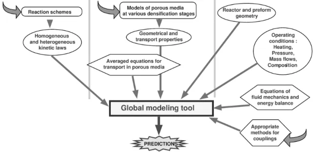
A global scheme is proposed in Fig. 2 : the idea is to sum up all knowledge inside a possibly unique modelling tool, that can be used for predictions and process optimization. Some particular issues have to be tackled : (i) the precise identification and handling of the reaction kinetics, which may be sometimes very complex, and that have to be separated from the transfer phenomena (a glance at the time scales in Fig. 1b points that it is far from being obvious), (ii) the description of geometry and transfer in the porous media, as a function of the degree of infiltration, requires to untangle the transfer modes from each other and to perform a change of scale, and (iii) macro-scale computations feature some non-trivial couplings that have to be addressed.
In the following parts, we will focus on points (ii) and (iii), which are more linked to the peculiarities of the fibrous medium, and show some recent results in these areas.
Global-scale models of CVI.
The main aim of reactor-scale modelling is to predict the infiltration time and homogeneity, making use of information coming from the lower scales, under the form of laws, for chemical reaction rates, transport in the porous medium, and its structural evolution. Once a model has been obtained, it is possible to perform process optimization, using some rational methods, like neural networks and fuzzy logic [26], etc …
Isothermal, isobaric CVI. I-CVI has been the most extensively studied process. In this case, solving a heat equation – at least inside the preform – is not required. The published works differ from each other by the following points :
- Description of the mass transfer phenomena : usually, Knudsen diffusion is considered in concurrence with ordinary diffusion, while viscous flow is neglected. This is a rather safe approximation since the mass Péclet number is around 0.01 or less. Multicomponent effects may be accounted for [27] : in this case, comprehensive models for transport, like the Dusty-gas Model (DGM) [28] or the Binary Friction Model [29] have to be used. They mix up the three transport modes (viscous flow, ordinary diffusion and Knudsen diffusion) in an intricate way. For instance, convection (i.e. overall mass transport) results not only from viscous flow, but also from Knudsen diffusion (the Klinkenberg effect), even if the latter transfer mode also has a separative character.
- Description of the porous medium structure and evolution : While many studies consider geometries as simple as a single pore [25,30], Ofori & Sotirchos [31] discuss extensively the influence of the structural model, i.e. the evolution laws for surface area σv, and tortuosity factors
with respect to diffusion, Knudsen diffusion and viscous flow. They show that bimodal pore structures are a good compromise between reactivity and accessibility.
- Definition of the resolution domain : Most of the studies are devoted to the density evolution in the preform itself ; however, the interaction with the surrounding gas flow has been studied [32,33,34,35]. It has been shown that the total infiltration time is affected by the flow rate and that the density field evolution is affected by both flow rate and reactor diameter. On the other hand, the final state of densification is not strongly affected by these parameters, since the initial discrepancies are compensated in the last stages.
- Degree of numerical effort : Large-mesh simulations with detailed physics have been produced (e.g. [32]), and they are a powerful tool for process scale-up and control; however many works have focused on a 1D simulation restricted to the preform, which is numerically much lighter and manage to provide useful information; with further simplifications on the physics and chemistry, analytical estimates for infiltration time and quality have been produced [36,37]. Two parameters have been shown to pilot the process, namely a Thiele modulus :
Φ = L Dkσv
eff (4)
and a characteristic infiltration time :
τ =
[
(υsC0)×σv k]
-1 [s] (5)Here, C0 is a reference precursor concentration. When the Thiele modulus becomes comparable
enough infiltration; this can be overcome by lowering temperature or pressure, but at the expense of increasing the total infiltration time. Non-linear chemical kinetics may be useful in helping to achieve uniform density, as shown by Middleman [38] on theoretical grounds and later in the case of carbon deposition from methane [30].
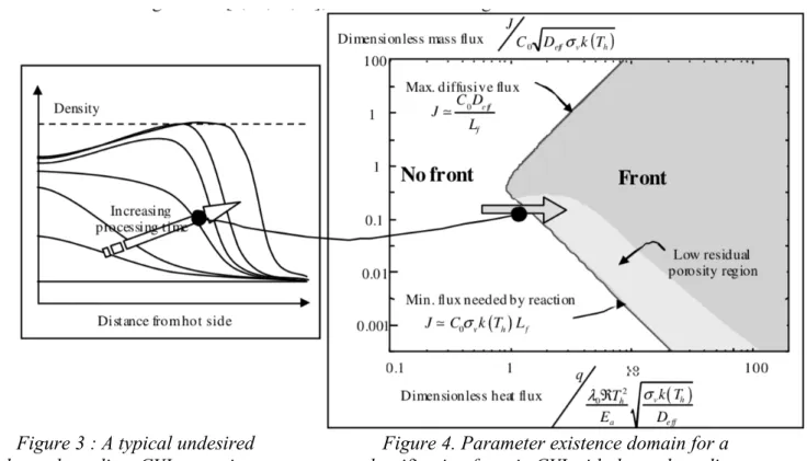
CVI with gradients. The introduction of a thermal gradient, obtained by various methods, helps dramatically in overcoming the drawbacks of I-CVI ; however, some cases in CVI with thermal gradients (TG-CVI) do not behave optimally. Indeed, reports on the "rapid process" [15] evidenced that, after a correct initial phase where densification would start from the hot side as expected, the density would eventually stop growing there, while keeping on increasing closer to the cold side. The resulting material has not an optimal density. This rather frequent situation, also obtained in various modelling studies [9,17,20,21], is schematized at figure 3.
Figure 3 : A typical undesired thermal-gradient CVI scenario.
Figure 4. Parameter existence domain for a densification front in CVI with thermal gradient.
On the other hand, reports on the forced-CVI [13] and on the "film-boiling" process [39] have mostly shown well-infiltrated materials. In this case, a densification front seems to exist since the beginning and until the end of the process. However, the latter process has other drawbacks, chiefly the strong energy consumption that underlies the presence of extreme gradients, and the necessity to handle flammable liquids together with a strong energy source. A detailed modelling study was carried out on this process, and validated with respect to experimental results [40,41]. Summing up its results and former works, its appeared that the central point in TG-CVI is the control of the existence of the densification front. A mathematical study [42,43] has shown that there are only two independent parameter sets that control the front, and that in the two-dimensional parameter space, there is a front existence domain, sketched at Fig. 4. The front existence is indeed linked to the following criterion : the mass flux must be at least equal to what the chemical reaction needs (lower branch of the frontier); however it is in itself limited by diffusion (upper branch of the frontier). Since the amount of reaction and diffusion fluxes is computed with respect to a length scale that is natural to the problem :
(where Th is the hot-side temperature and λ0 the solid-phase heat conductivity in W.m-1.K-1), then
there exists a minimal heat flux q (W.m-2) which allows to fulfil the mass flux criterion, such that
the Thiele modulus defined at eq. (4) with L = Lf is unity. This means that the critical flux decreases
when : (i) the activation energy increases, (ii) the gas diffusion coefficient increases (with a pressure decrease unless a Knudsen regime is attained), (iii) the hot side temperature decreases, (iv) the solid phase conductivity decreases, and (v) the fibre diameter increases (since σv ~ df-1).
The diagram of Fig. 4 helps to understand how the undesired infiltrations of Fig. 3 appear : when processing starts, the heat gradient is not strong enough and the critical condition for q is not fulfilled ; later on, the heat flux increases and eventually traverses the existence boundary, as shown by the arrow on the diagram. Also, it has been shown that the residual porosity tends to zero when the system lies close to the lower frontier of the existence diagram : in practice, it will be difficult to distinguish between such a behaviour and a total infiltration. In this case, the velocity is approximately equal to Lfτ-1 (where τ is given by eq. (5)), and in any case the front width is roughly
equal to Lf [42].
Forced-CVI has been studied either in isothermal conditions [10,44] and in thermal-gradient conditions [11-13,45], the latter being more extensively employed for obvious reasons of better infiltration uniformity. An analogy may be performed with non-forced CVI by considering a modified Thiele modulus (see eq. 4) where diffusion is replaced by its viscous-flow equivalent [44]:
Φv = L σBpvkµ
e (7)
where µ is the gas viscosity (Pa.s), B the porous medium permeability (m2) and pe the exit pressure
(Pa). Again, values of Φv above unity lead to catastrophic density gradients ; optimal values of the
pressure differences may be worked out for a given set of conditions, i.e. a given value of Φv.
Pushing further the analogy, one can easily make use of the thermal-gradient results summarized at figure 4 by replacing everywhere the diffusion coefficient D by its viscous flow analogue Bpe/µ.
Pressure-pulsed CVI (P-CVI) has also been modeled [46,47] and the beneficial effect of an optimal pressure pulse frequency on the infiltration uniformity has been illustrated. If thermal gradients are superimposed, then a perfectly controlled densification homogeneity may be attained [48] ; this has been confirmed experimentally by the so-called “TP-CVI” (temperature and pressure pulsed CVI) modification [49].
Pore-scale modelling for CVI
The global-scale modelling studies have shown that a fundamental point in the infiltration process is the evolution of the porous medium properties, which are at least : (i) the internal surface area, (ii) the effective binary and Knudsen diffusivities, (iii) the permeability, and (iv) the thermal conductivity. One has to provide accurate laws for these geometrical and transport-related properties as functions of infiltration progress, or of porosity, in complex fibre arrangements. This is typically achieved with pore-scale modelling.
Ideal media. During many years the focus has been set on the properties of ideal media, like random beds of cylinders, either fully overlapping or partially overlapping, or of capillaries. The methods were principally aimed at a separate evaluation of all geometrical and transport properties. In I-CVI the main properties of interest are the internal surface and the effective binary and Knudsen diffusivities: estimates for a variety of porous media have been obtained, using a Monte-Carlo/Random Walk technique [50,51]; effective thermal conductivities were computed by the same technique [52]. For F-CVI, permeability estimates have been assessed for a “node-bond” equivalent pore network [53]; more recently, a method proposed by Johnson, Koplik and Schwartz [54], allowing estimation of permeabilities from the knowledge of effective diffusivities has been tested and validated by Tomadakis and Robertson [55] for a variety of fibrous media. Skamser et al.
have estimated both permeabilities and thermal conductivities for unidirectional fibre bundles, either from an ideal model or from computer-generated 2D images [56].
Contribution from X-ray CMT. In general, and except for permeabilities, the amount of numerical estimations exceeds by far the quantity of direct measurements; this is due to the working scale that is very small. However, there exists at least one experimental procedure that allows such verification, and it is X-ray computerized micro-tomography (CMT). It has been used successfully to characterize the structure of SiC fibre cloth lay-up preforms at macro-pore scale (pixel size of 15.6 mm) [57,58]. Much more recently, carbon-fibre preforms also have been examined at fibre-scale and macro-pore fibre-scale [59]. An image segmentation algorithm specific to phase-contrast images obtained with synchrotron X-rays on poorly absorbent materials like carbon has been developed to make it possible [60]. The computation of geometrical parameters, such as surface area and pore size distribution, directly from the images, has been validated against experimental data [61]. The fibre-scale results for binary and Knudsen diffusion were coherent with the estimates on similar ideal media [50]. A double change-of-scale strategy allowed to integrate the fibre-scale results and compare the macro-scale values to experimental data, with satisfactory results on thermal conductivity [62], permeability and Knudsen diffusivity [63].
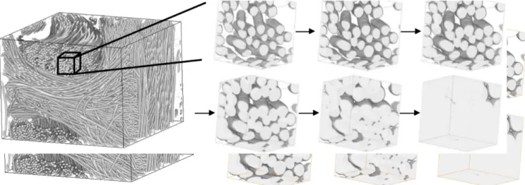
Pore-scale simulation of chemical deposition. The study of geometry and transport in families of ideal media has always rested on the idea that there was only one way for the properties to vary with porosity ; usually some kind of “dilation” of the solid-phase is the underlying assumption. Indeed, solving eq. (2) on a single fibre in the limit of infinitely rapid diffusion (i.e. constant precursor concentration) leads to a preserved circularity and a fibre radius growth. However, actual CVI conditions usually imply some pore-scale diffusional limitations : this motivates further efforts at predicting the detailed geometrical evolution of complex porous media. Jin & Wang [64] have developed a level-set method suited to such a simulation, assorted to a closed pore detection, and present results in the kinetic limit in a small arrangement of balls. By adding a sticking algorithm, a “voxel filling” procedure, and a closed pore detector, the Monte-Carlo Random Walk diffusion simulator [51] has been turned into another pore-scale infiltration simulator. The differences between a purely geometrical dilation – which corresponds to the kinetic limit, the sticking coefficient being lower than 0.01 – and a diffusional competition case – sticking coefficient = ½ – are illustrated on a granular medium [65], with a more pronounced permeability decrease in the second case. Fig. 5 gives an example of what the numerical procedure is able to perform on 100x100x100 sub-images of an X-ray CMT dataset [63].
Figure 5 : An example of a pore-scale infiltration simulation on a 3D image extracted from CMT data.
With such a tool in hand, it becomes possible to work out more rationally the notion of
infiltrability, that is, the ability of a fibrous medium to let itself penetrate by the gases while
receiving intra-pore deposits. This depends not only on the fibre arrangement, but also on the precise physico-chemical regime.
Summary and outlook
The modelling of CVI is an exciting area in the sense that it connects a truly important application in materials fabrication to up-to-date issues in various academic domains of interest, featuring theoretical chemical engineering, physics of transport in porous media, image processing, numerical methods, applied mathematics, etc …
CVI modelling is a rather mature scientific area : a large quantity of studies have identified the main phenomena, scales, couplings, and given useful optimization guidelines to engineers. Original physico-chemical couplings are identified and specific methods have been designed to tackle them. However, fully integrated multi-scale approaches are not yet frequent. The current efforts concern the non-isothermal variations of the process, and the pore-scale study of infiltration, which deserves more direct experimental validation. X-ray CMT is a promising technique for such a duty.
References
[1] G. Savage: Carbon/Carbon composites (Chapman & Hall, London 1993). [2] R. Naslain and F. Langlais: Mater. Sci. Res. Vol 20 (1992), p. 145.
[3] H. O. Pierson: Handbook of Thin-Film Deposition Processes and Techniques. (Noyes, Park Ridge, NJ, USA 1988).
[4] R. Naslain, J.-Y. Rossignol, P. Hagenmuller, F. Christin, L. Héraud and J. J. Choury: Rev. Chim. Min. Vol. 18 (1981), p. 544.
[5] R. Naslain and F. Langlais: High Temperature Science Vol 27 (1990), p. 221.
[6] T. M. Besmann , B. W. Sheldon, R. A. Lowden and D. P. Stinton: Science Vol. 253 (1991), p.1104.
[7] I. Golecki: Mater. Sci. Eng. Vol. R20 (1997), p. 37.
[8] S. M. Gupte and J. A. Tsamopoulos: J. Electrochem. Soc. Vol. 136 (1989), p. 555. [9] R. Melkote and K. F. Jensen: Mater. Res. Soc. Symp. Proc. Vol. 168 (1990), p. 67.
[10] Y. G. Roman, J. F. A. K. Kotte and M. H. J. M. de Croon: J. Eur. Ceram. Soc. Vol 15 (1995), p. 875
[11] T. L. Starr, A. W. Smith and G. F. Vinyard: Ceram. Eng. Sci. Proc. Vol. 12 (1991), p. 2017. [12] T. M. Besmann and J. C. McLaughlin: Proc. of the 18th Annual conference on Composites and Advanced Materials – B Vol. 15 (1994), p. 897.
[13] S. Vaidyaraman, W. J. Lackey, G. B. Freeman, P. K. Agrawal and M. D. Langman: J. Mater. Res. Vol. 10 (1995), p. 1469.
[14] I. Golecki, C. Morris and D. Narasimhan : US Patent no. 5 348 774 (1994).
[15] I. Golecki, R. C. Morris, D. Narasimhan and N. Clements: Ceram. Trans. Vol. 79 (1996), p. 135
[16] D. Gupta and J . W Evans: J. Mater. Res. Vol. 6 (1991), p. 810.
[18] D. J. Devlin, R. P. Currier, R. S. Barbero and B. F. Espinoza: Mater. Res. Soc. Symp. Proc. Vol. 250 (1992), p. 245.
[19] D. J. Devlin, R. S. Barbero and K. N. Siebein: Electrochem. Soc. Proc. Series Vol. PV 96-5 (1996), p. 571.
[20] V. Midha and D. Economou: J. Electrochem. Soc. Vol. 144 (1997), p. 4062.
[21] D. Leutard, G. L. Vignoles, F. Lamouroux and B. Bernard: J. Mater. Synth. and Proc. Vol. 9 (2002), p. 259.
[22] M. Houdayer, J. Spitz and D. Tran Van: US Patent no. 472 454 (1984). [23] E. Bruneton, B. Narcy and A. Oberlin: Carbon Vol. 35 (1997), p. 1593. [24] K. Sugiyama and Y. Kurisu: J. Mater. Sci. Vol. 27 (1992), p. 4070
[25] R. Fédou, F. Langlais and R. Naslain: J. Mater. Synth. and Proc. Vol. 1 (1993), p. 61. [26] A.-J. Li, H.-J. Li, K.-Z. Li and Z.-B. Gu: Science in China Vol. E46 (2003), p. 173. [27] J. Y. Ofori and S. V. Sotirchos: Ind. Eng. Chem. Res. Vol. 35 (1996), p. 1275.
[28] E. A. Mason and A. P. Malinauskas: Gas transport in porous media: the Dusty-Gas Model (Elsevier, The Netherlands, 1983).
[29] P. J. A. M. Kerkhof: Chem. Eng. J. Vol. 64 (1996), p. 319.
[30] W.-G. Zhang and K. J. Hüttinger: Compos. Sci. Technol. Vol. 62 (2002), p. 1947 [31] J. Y. Ofori and S. V. Sotirchos: J. Electrochem. Soc. Vol. 143 (1996), p. 1962 [32] P. McAllister and E. E. Wolf: AIChE J. Vol. 39 (1993), p.1196
[33] M. Sasaki: J. Mater. Synth. and Proc. Vol. 2 (1994), p. 133 [34] V. G. Minkina: Theor. Found. Chem. Eng. Vol. 31 (1997), p. 248
[35] N. Reuge and G. L. Vignoles: J. Mater. Proc. Technol. Vol. 166 (2005), p. 15
[36] H.-C. Chang, D. Gottlieb, M. Marion and B. W. Sheldon: J. Sci. Comput. Vol. 13 (1998), p. 303
[37] A. D. Jones Jr: Appl. Math. Modell. Vol. 30 (2006), p. 293 [38] S. Middleman: J. Mater. Res.Vol. 4 (1989), p. 1515
[39] D. Rovillain, M. Trinquecoste, E. Bruneton, A. Derré, P. David and P. Delhaès: Carbon Vol. 39 (2001), p. 1355
[40] J.-F. Lines, G. L. Vignoles, J.-M. Goyhénèche and J.-R. Puiggali: J. Phys. IV France Vol. 120 (2005), p. 291
[41] G.L. Vignoles, J.-M. Goyhénèche, P. Sébastian, J.-R. Puiggali, J.-F. Lines, J. Lachaud, P. Delhaès and M. Trinquecoste : Chem. Eng. Sci., to appear (2006)
[42] G. L. Vignoles, N. Nadeau, C.-M. Brauner, J.-F. Lines and J.-R. Puiggali: Ceram. Eng. and Sci. Proc. Vol. 26 (2005), p. 187
[43] N. Nadeau, G. L. Vignoles and C.-M. Brauner: Chem. Eng. Sci., submitted (2006) [44] J. Y. Ofori and S. V. Sotirchos: J. Electrochem. Soc. Vol. 144 (1997), p. 274
[45] K. J. Probst, T. M. Besmann, D. P. Stinton, R. A. Lowden, T. J. Anderson and T. L. Starr: Surf. Coat. Technol. Vol. 120-121 (1999), p. 250
[46] S. V. Sotirchos: AIChE J. Vol. 37 (1991), p. 1365
[47] S. V. Sotirchos: in High Temperature Ceramic Matrix Composites, p. 241 (Woodhead Publishing Ltd., UK, 1993).
[48] J. Y. Ofori and S. V. Sotirchos: J. Mater. Res. Vol. 11 (1996), p. 2541
[49] S. Bertrand, J.-F. Lavaud, R. El-Hadi, G. L. Vignoles and R. Pailler: J. Eur. Ceram. Soc. Vol. 18 (1998), p. 857
[50] S. V. Sotirchos and M. M. Tomadakis: Mater. Res. Soc. Symp. Proc.Vol. 168 (1990), p. 73 [51] G. L. Vignoles: J. de Phys. IV Vol. C5 (1995), p. 159
[52] M. M. Tomadakis and S. V. Sotirchos: J. Chem. Phys. Vol. 98 (1993), p. 616 [53] T. L. Starr: J. Mater. Res. Vol. 10 (1995), p. 2360
[54] D. L. Johnson, J. Koplik and L. M. Schwartz: Phys. Rev. Lett. Vol. 57 (1986), p. 2564 [55] M. M. Tomadakis and T. J. Robertson: J. Compos. Mater. Vol. 39 (2005), p. 163
[56] D. J. Skamser, D. P. Bentz, R. T. Coverdale, M. S. Spotz, N. Martys, H. Jennings and D. L. Johnson: J. Amer. Ceram. Soc. Vol. 77 (1994), p. 2669
[57] J. H. Kinney, T. M. Breunig, T. L. Starr, D. Haupt, M. C. Nichols, S. R. Stock, M. D. Butts, and R. A. Saroyan: Science Vol. 260 (1993), p. 789
[58] S.-B. Lee, S. R. Stock, M. D. Butts, T. L. Starr, T. M. Breunig, and J. H. Kinney: J. Mater. Res. Vol. 13 (1998), p. 1209
[59] O. Coindreau and G. L. Vignoles: Mater. Sci. Forum Vol. 455-456 (2004), p. 751 [60] G. L. Vignoles: Carbon Vol. 39 (2001), p. 167
[61] O. Coindreau and G. L. Vignoles, J. Mater. Res. vol. 20 (2005), p. 2328
[62] O. Coindreau, G. L. Vignoles, and J.-M. Goyhénèche: Ceram. Trans. Vol. 175 (2005), p. 71 [63] O. Coindreau, PhD Thesis, University Bordeaux 1 (2003)
[64] S. Jin and X.-L. Wang: J. Comput. Phys. Vol. 186 (2003), p. 582
[65] D. Bernard and G. L. Vignoles, Theor. and Appl. of Transp. in Porous Media Vol. 17 (2000), p. 217