HAL Id: in2p3-00021791
http://hal.in2p3.fr/in2p3-00021791
Submitted on 29 Nov 2013
HAL is a multi-disciplinary open access
archive for the deposit and dissemination of
sci-entific research documents, whether they are
pub-lished or not. The documents may come from
teaching and research institutions in France or
abroad, or from public or private research centers.
L’archive ouverte pluridisciplinaire HAL, est
destinée au dépôt et à la diffusion de documents
scientifiques de niveau recherche, publiés ou non,
émanant des établissements d’enseignement et de
recherche français ou étrangers, des laboratoires
publics ou privés.
optimisation method for the CIME cyclotron injection
system
P. Bertrand, D. Bibet, M.P. Bourgarel, B. Bru, A. Chabert, F. Daudin, M.
Duval, M. Ozille, C. Ricaud, F. Varenne
To cite this version:
P. Bertrand, D. Bibet, M.P. Bourgarel, B. Bru, A. Chabert, et al.. SPIRAL facility at GANIL :
ion beam simulation and optimisation method for the CIME cyclotron injection system. 15th
In-ternational Conference on Cyclotrons and their Applications, Jun 1998, Caen, France. pp.458-461.
�in2p3-00021791�
SPIRAL FACILITY AT GANIL: ION BEAM SIMULATION AND OPTIMISATION METHOD FOR THE CIME CYCLOTRON INJECTION SYSTEM
P. BERTRAND, D. BIBET, M.P. BOURGAREL, B. BRU, A. CHABERT, F. DAUDIN, M. DUVAL, M. OZILLE, Ch. RICAUD, F. V ARENNE
GANIL (CEAlDSM, CNRS/IN2P3), 14076 Caen cedex 5, France
This paper presents an overview of the codes used for the design of the CIME injection elements (in panicular the central geometry and the mflector) as well as for the off-line and on-line optimisation of the injection parameters.
1. Introduction
SPIRAL, the new GANIL radioactive ion beam facility, has been under construction since 1994 and is now being tested with stable beams [1].
From the beginning of the construction, it was decided to build a set of simulation programs allowing to choose the best compromises during the design and to optimise the beam behaviour from the ECR ion source up to the physicist experimental areas. For this purpose, we have updated existing codes for the beam transport line, and developed new codes for the calculation of the 3D electric fields and the beam dynamics in the cyclotron.
This paper gives a description of these codes, and explains the methodology adopted for the design of the cyclotron central region and the optimisation of the parameters. 2. Generation of electromagnetic fields 2.1 Magnetic fields: TOSCA and measurements
The magnetic fields at GANIL have been regularly calculated with TOSCA [2] since 1990. For the SPIRAL project, the CIME cyclotron [3]. most of the dipoles of the low energy transport line and the injection solenoid were designed using TOSCA.
For CIME, we have calculated a set of field maps at different magnetic levelS, isochronised for different RF frequencies. Each map, extracted from the TOSCA files, contains the vertical field component Bz in the mid plane, and the derivatives dBx / dZ, dB y / dZ, t,xyBz , obtained by subtracting from Bz (x,y,O) the TOSCA values in the plane z = 5mm. This avoids a derivation of the mid plane Bz component, which could generate noise and discontinuities. Associated with these computed data, a set of measured field maps has been performed with 93 Hall probes disposed every 1 and 2 em in radius on an arm rotating every 0.9 degree. The measurements were made in the presence of the eJection elements, but in the absence of the RF cavities. 2.2 Electric fields: CHA3D, VINFLEC and PL TMG
The axial injection in the CIME compact cyclotron uses either a Muller inflector [4] and RF cavity noses well suited for the harmonics 2, 3 and 4 (34 mm curvature radius), or a Belmont-Pabot inflector [5] with specific RF cavity noses for the harmonics 4 and 5 (45 mm curvature radius).
To design and simulate these 2 cyclotron central regions, we have developed a specific code called CHA3D [6]. using the capabilities of modern computers:
CHA3D is a Fortran 90 3D-code running on paralleVvector computers such as the CRA Y J90 (16 shared memory processors) and the CRA Y T3E (256 distributed memory processors). The Laplacian problem, with its Dirichlet boundary conditions, is discretised using a finite difference scheme on a very thin regular 3D mesh of .25 mm, leading typically to 8 millions unknowns. The corresponding sparse linear system is solved using a completely parallel version of the conjugate gradient algorithm. In order to respect the real shapes of the considered object, we extract automatically from the EUCLID CAD software [7] the electrode information in the form of a set of Bezier surfaces. Then they are visualised and checked with the A VS software [8], and projected into the mesh for the calculation. Giving to the machine tool the same CAD geometric information, we are sure that the calculated 3D potential reflects exactly the real object (fig. 1).
The RF nose cavities and the Muller inflector have been calculated and manufactured in this way, as well as other GANIL devices such as the SIRA electrostatic deflector. In the case of the inflectors, we have used also the specific code VINFLEC [11] which generates a simplified geometry without the resort to the EUCLID CAD software.
The optimisation of the SPIRAL buncher electrodes was done using the 2D finite element PL TMG code [9].
3. Beam dynamic codes 3.1 Cyclotron CIME : LIONS
The software LIONS [10], developed for the CIME cyclotron presents the following characteristics:
Written in Fortran 90 (2600 instructions), it uses intensively the array notation and intrinsic functions, giving typically 3
times less lines than Fortran 77 and increasing the legibility and the maintenance of the program.
LIONS works in the (x,y,z) absolute coordinate system, using the relativistic Lorentz equations in
(x,p)
with the time as the evolution variable. The equations of motion are discretised using the Leap-frog algorithm which can workforward or backward, by changing the sign of the time step.
The adopted formalism allows to generate a particle bunch taking into account the correlations chosen or required in the 6D phase space, at any point in the cyclotron. In the case of an initial condition at some intermediate radius in the machine, we take into account the non linear «torsion» effects which should have been created by the acceleration in the previous turns.
LIONS can stop automatically the particles which hit obstacles, for example the pillars of the cavity noses. It allows also to superpose perturbations to the basic magnetic field and to simulate a mono or multi turn extraction.
3.2 Inflectors: PELLCE
PELLCE [11] is a RK4 beam dynamic code dedicated to the study of the inflectors. It uses the cyclotron magnetic field from TOSCA and the electrostatic field given by CHA3D or VINFLEC, and performs a tracking of particles through the inflector in different ways:
- at first, the reference particle is launched from the entrance to the exit, or from the middle up to the entrance or the exit. By an iterative process with the potential solvers, this allows to adjust the inflector length so as to tune the zero order. - after that, we launch 6 particles, each of them having one small perturbation among HセクL@ セクGL@ セケL@ セケGL@ セiL@ セーOーI@ so as to compute the first order transfer matrix.
- then we launch a complete bunch respecting the correlations given by LIONS (§3.l) and look at the acceptance and non linearities of the inflector (fig. 2).
3.3 Beam lines to first order: GALOPR
GALOPR [12] is a first order 3D beam transport code. It
deals with usual optical devices represented by their analytical transfer matrices and takes into account any special optical device defined by its numerical transfer matrix (for example Belmont-Pabot and Muller inflectors). The beam way be continuous, bunched or undergoing a bunching process. The beam line parameters can be optimised to fit any element of the 6x6 transfer and/or covariance matrices, in order to obtain the maximum transmission efficiency. Space charge is optionally taken into account by adding in each transfer matrix its effects as linear internal forces.
3.4 Beam lines to all orders: SOSO
SOSO [13] is a Fortran 77 mono and multi particle code coming in complement to the code GALOPR : once a given
transport line has been optimised to the first order, SOSO takes into account the non linear effects generated by the real electromagnetic fields coming from TOSCA, CHA3D, measurements or analytic formulae.
Transport lines are described by a succession of elements along the z axis (straight parts) or the
e
angle (deviations). In the last version, the following elements are accepted: drifts, dipoles, quadrupoles, sextupoles, solenoids, electrostatic or RF lenses and deflectors, targets, steerers ...The Lorentz equations are discretised using the RT<4 algorithm, with z or
e
as the evolution variable.When SOSO is used up to the exit of the electrostatic inflector, a transformation of the particle data set is performed in order to present the bunch in the
(x, p,
t)
system of coordinates, as required by LIONS.
4. Methodology for beam dynamics
The basic specifications of the cyclotron CIME and its beam transport lines being chosen, an important step consists in determining the best shapes of the cavity noses and of the associated inflector, proceeding by successive iterations
between beam dynamic simulations and geometric
corrections, while having in mind the following criteria: - avoid electric breakdowns in the nose neighbourhood. - allow a rotation degree of freedom for the inflector, depending on the harmonic.
- deal correctly with the correlations in the 6D phase space so as to optimise the beam transmission.
- check that the solution produces a beam well suited for the ejection.
In order to respect the above criteria, the following method was adopted :
For given ion specie, magnetic field and RF frequency and harmonic, we define a reference particle and an initial bunch, at about 50 cm from the cyclotron centre, respecting the ideal energy and the 6D matching conditions at this point. Then we launch the reference particle in backward,
adjusting slightly the RF amplitude and if necessary the first and second trimcoils, so as to be well centred between the pillars of the cavity noses. Then we launch in backward the
corresponding 6D bunch up to the injection point, where we keep the particles whose energy dispersion is in the range allowed by the injection line (about 1 %). The 6x6 beam matrix of this filtered bunch is decomposed so as to make appear the correlations (r,r'), (r',$), (r,$) and (z,z'), checking that the others can be neglected.
An important compromise occurs at this step, because the ideal position of the vertical injection axis depends upon the harmonics: by an iterative backward-forward processus, we
generate successive nose geometries with the corresponding potential fields, checking the electric breakdown risks, the rotation degree of freedom of the inflector and the dynamics in the cyclotron. It appeared that the best position for the
Figure 1 : 3D view of the CIME central region . The same geometric information coming from EUCLID is given to the solver CHA3D and to the machine tool.
セ@ 100 E
£
80 x 60 a. 40 20 0 -20 -40 -60 -80 - 100 セ@ 100 "01
80 x 60 a. 40 20 o -20 -· 40 -60 -80 -100[
- 4 -2 0 2 4 x (mm)t, ... , ... , "',,.,
"I -50 - 25 o 25 50 Phase (dq)E
£
>-a. E E 50 40 30 20 10 0 -iO -20 -30 - 40 -50 5 4 3 2 o - I -2 -3 -4 -5Figure 2 : Beam envelope through the MUller inflector, using the CHA3D solver and the PELLCE dynamic code.
-5 o 5 y (mm) .' .;";" -100 -50 o 50 lCO Ph ase (dg)
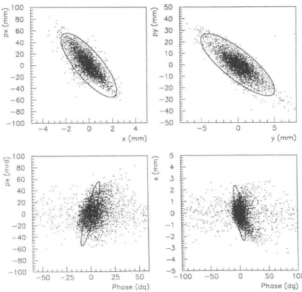
Figure 3 : Correlations at the injection point.
Comparison between the ideal matching given in backward by LIONS (ellipses) and the forward result given by SOSO.
vertical injection axis was located at 49.7 mm from the central axis and 113° from the first cavity. We have checked that this choice allowed also to set the Belmont-Pabot inflector, an electrostatic quadrupole (vertical focusing) and the corresponding cavity noses adapted to the harmonics 4 and 5 with the 45 mm injection radius.
At this step, we can give to PELLCE and GALOPR all the information in terms of the reference particle and the 6D correlations of the bunch : using CHA3D, which calculates the inflector 3D potential taking into account the fringing fields and the presence of a phase probe, PELLCE determines the best choice in terms of geometric corrections. Then GALOPR operates in the first order to determine the best set of parameters of the injection elements and the low energy beam line.
The third step consists in defining a continuous beam at the ECR source extraction with a realistic density distribution, and to transfer it with SOSO up to the inflector exit, with or without bunching. Slight adjustments of the parameters established with GALOPR are generally required to take into account the non linearities due to the real 3D fields.
As a final step, LIONS takes the bunch from SOSO as an initial condition (fig. 3) and computes a forward acceleration from the CIME injection up to the extraction exit.
5. Preliminary results and comparisons
Although the acceleration of stable beams is not completely achieved, the first experimental results are in good agreement with the simulations.
Experiments were performed in two cases at a 14.4 Mhz RF frequency in harmonic 3 (10 Mev/amu acceleration) : - oxygen 1605+ with a ECR source tension of 17.4 KY and a
magnetic field of 1 Tesla.
- oxygen 1804+ with a ECR source tension of 25.4 KY and a
magnetic field of 1.4 Tesla.
The tuning of the low energy transfer line up to the entrance of the cyclotron yoke corresponds quite exactly to the theoretical parameters, so that it is straightforward to transport the beam up to the axial injection line, with a transmission over 90% for a 80 n.mm.mrad radial and vertical emittance.
The tuning of the axial injection line is a bit more difficult: the only diagnostic available today is the beam behaviour in the cyclotron; we have also an approximate knowledge of the magnetic field created by the injection solenoid and skew quadrupoles together with the cyclotron. However, we have checked that the various parameters acted in conformity with the simulations in particular the vertical and horizontal steering, and the beam matching of the injected beam. The linear buncher itself is very easy to tune: there is only 2 parameters: the potential and the phase.
The transmission through the axial injection line and up to the cyclotron radius 1.400 meter is 10% without buncher , and over 50% with it.
When applying the theoretical currents to the 11 trimcoils, the isochronism measured with the phase probes was found to be very good: just a slight modification of the main current was necessary to adjust the CIME magnetic level.
6.
Conclusions
The intensive use of simulations with modern parallel computers allows to design and to optimise a cyclotron and its associated beam lines, avoiding the resort to scale models and thus saving time and money. This also allows further interactions with the on-line tuning.
References
[1] M.P. Bourgarel, SPIRAL facility: First results on the CIME cyclotron obtained with stable ion beams, (1998) (this conference).
[2] Vector Fields Ltd., TOSCA, Oxford, England.
[3] M. Duval et aI., SPIRAL project: status of the cyclotron. Xyth Int. Conf. Magnet Technology (1997).
[4] R.W. Muller, Novel inflectors for cyclic accelerators, NIM 54, pp 29-41 (1967).
[5] JL. Belmont, J.L. Pabot, Study of axial injection for the Grenoble cyclotron, IEEE Trans. Nucl. Sc. NS-13, 191 (1966).
[6] P. Bertrand, Recent Fortran 90 developments in 3D electric fields calculations and applications related to the SPIRAL project at GANIL, CAP 1996.
[7] EUCLID CAD software, Matra Datavision. [8] A YS, Advanced Yisual System, UNIRAS. [9] R.E. Bank, PL TMG , SIAM (1990) , USA.
[10] P. Bertrand , LIONS: a new set of Fortran 90 codes for the SPIRAL project at GANIL. 4th ICCPO, Japan, (1994)
[II] S. Chel , thesis, GANIL T 89-02 (1989).
[12] B. Bru , GALOPR: a beam transport program with space-charge and bunching, 3rd ICCPO (1990). [13] A. Chabert, SOSO, GANIL report.
[14] A. Chabert et aI., the linear Buncher of SPIRAL, GANIL S 97 01.