HAL Id: cea-02360134
https://hal-cea.archives-ouvertes.fr/cea-02360134
Submitted on 20 Nov 2019
HAL is a multi-disciplinary open access
archive for the deposit and dissemination of
sci-entific research documents, whether they are
pub-lished or not. The documents may come from
teaching and research institutions in France or
abroad, or from public or private research centers.
L’archive ouverte pluridisciplinaire HAL, est
destinée au dépôt et à la diffusion de documents
scientifiques de niveau recherche, publiés ou non,
émanant des établissements d’enseignement et de
recherche français ou étrangers, des laboratoires
publics ou privés.
nanosecond Nd-YAG lasers
A. Semerok, Sv. Fomichev, J.-M. Weulersse, F. Brygo, P.-Y. Thro, C. Grisolia
To cite this version:
A. Semerok, Sv. Fomichev, J.-M. Weulersse, F. Brygo, P.-Y. Thro, et al.. Heating and ablation
of tokamak graphite by pulsed nanosecond Nd-YAG lasers. Journal of Applied Physics, American
Institute of Physics, 2007, 101 (8), pp.084916. �10.1063/1.2721750�. �cea-02360134�
A. Semerok,a) S.V. Fomichev,b) J.-M. Weulersse, F. Brygo, and P.-Y. Thro CEA Saclay, DEN/DPC/SCP/LILM, Bˆat. 467, 91191 Gif sur Yvette, France
C. Grisolia
CEA Cadarache, DSM/DRFC, Bˆat. 506, 13108 Saint Paul Lez Durance, France
The results on laser heating and ablation of graphite tiles of thermonuclear tokamaks are pre-sented. Two pulsed Nd-YAG lasers (20 Hz repetition rate, 5 ns pulse duration and 10 kHz repeti-tion rate, 100 ns pulse durarepeti-tion) were applied for ablarepeti-tion measurements. The ablarepeti-tion thresholds
(1.0 ± 0.5 J/cm2 for 5 ns and 2.5 ± 0.5 J/cm2 for 100 ns laser pulses) were determined for the Tore
Supra tokamak graphite tiles (backside) non-exposed to plasma. The high repetition rate Nd-YAG laser (10 kHz, 100 ns pulse duration) and the developed pyrometer system were applied for graphite heating measurements. Some unexpected features of laser heating of the graphite surface were ob-served. They were explained by the presence of a thin surface layer with the properties different from those of the bulk graphite. The theoretical models of laser heating and near-threshold ablation of graphite with imperfectly adhered layer were developed to interpret the experimental results.
PACS numbers: 28.52.Fa, 44.10.+i, 79.20.Ds, 81.05.Uw
I. INTRODUCTION
The excessive tritium trapping in deposited layers on tokamak plasma-facing components is seen as a se-vere problem for efficient operation of thermonuclear fu-sion reactors.1,2,3,4,5,6,7 To detritiate and clean
plasma-facing surfaces of the future ITER, the completely op-tical methods of laser heating8,9,10,11,12 (LH) and laser
ablation13,14,15,16,17,18 (LA) can be suggested. Graphite
surface detritiation by continuous wave (CW) lasers in the heating regime with the temperatures up to 2300 K was reported in Ref.9,10. LH was applied to release drogen isotopes from the deposited layer and to make hy-drogen concentration measurements,19rather than to
re-move the carbon deposit from the surface. For graphite, LA is observed when the surface temperature reaches the sublimation temperature TS ≈ 4200 K.20,21 CW lasers
may heat graphite surface up to this sublimation tem-perature only with the power of 1 kW or above (assum-ing 1 mm laser spot diameter). Powerful (10 − 100 W) pulsed Nd-YAG lasers of a high repetition rate are ap-propriate for decontamination of plasma-facing compo-nents in tokamaks by LA.22,23,24 Laser beam transport
to the cleaning zone by an optical fiber allows to remove the laser system away from the contaminated zone and to perform a remote surface treatment. Personnel safety, re-duced waste volume, laser beam accessibility to shadowed areas, and possible complete automation of the process are regarded as attractive advantages of laser decontam-ination.
To avoid graphite tiles damage during surface detri-tiation, LA thresholds for graphite and deposited layer
a)E-mail: alexandre.semerok@cea.fr
b)On leave from RRC “Kurchatov Institute”, Kurchatov pl.,
123182 Moscow, Russia
should be determined. The ablation threshold and rate of a carbon deposit depend on the deposited layer prop-erties (thickness, density, thermal and optical parame-ters). To our knowledge, these properties are not suf-ficiently known. They may differ significantly from the corresponding properties of tokamak graphite, which are also not well known.20,21,25,26,27,28 To obtain the layer
and/or substrate properties, it is necessary to measure the thermal response of the surface to the transient heat pulse.29
To study laser detritiation of tokamak graphite tiles, two experimental laser benches were developed in our laboratory (CEA Saclay, France). The first experimen-tal set-up based on a commercial Q-Switched Nd-YAG laser (“Brilliant” QUANTEL) was designed to study LA with short (4 − 10 ns FWHM) laser pulses of a low rep-etition rate (20 Hz or single pulses). The second set-up was based on a Q-Switched high repetition rate Nd-YAG laser developed in CEA Saclay. It was applied for LA and LH experiments with longer (≈ 100 ns FWHM) pulses of a laser repetition rate (νL) up to 10 kHz. Laser
radia-tion at the wavelength (λL) of 532 nm provided up to
180 mJ pulse energy with 5 ns pulses at low νL = 20 Hz
and up to 100 W mean power with 100 ns pulses at high νL= 10 kHz. The 5 ns Gaussian laser beam was
homog-enized by a diaphragm with imaging the central zone of the beam onto the surface. The 100 ns laser beam was transported to the interaction zone by a multimode optical silica fiber of 15 m length, 1 mm core diameter, and 0.2 numerical aperture. Laser beam intensity dis-tribution was homogeneous at the fiber exit. Thus, the homogenized laser beams of 0.6 − 3 mm spot size (de-pending on focusing) on the irradiated surface were used in the experiments with two benches. Different fluences for 5 ns laser were obtained by varying the laser pulse en-ergy, but keeping the fixed laser spot diameter (1 mm). For 100 ns laser pulses, different laser fluences at the con-stant laser pulse energy (6 mJ) were obtained by varying
the laser spot diameter.
Theoretical models of LH and near-threshold LA of complex surfaces with a layer by periodically re-peating nanosecond laser pulses were developed. The models may describe LH and LA both with the temperature-dependent matter parameters and their mean temperature-independent values. The three-dimensional (3D) analytical LH model30,31 provides
cal-culations of the heating temperature for any number of applied laser pulses. The one-dimensional (1D) numeri-cal model of LA of sublimating materials (graphite) al-lows to calculate LA depth with consideration of the tem-perature dependences (if known) of the surface proper-ties. The intermediate adhesion between the layer and the substrate was applied in both models. The compara-tive experimental and theoretical studies on LH and LA of graphite samples allowed to characterize a deposited carbon layer and to determine some poorly known prop-erties of tokamak graphite.
The paper presents the results on near-threshold LA and LH of tokamak graphite (backside non-plasma-facing surfaces of Tore Supra tokamak tiles) by pulsed nanosec-ond Nd-YAG lasers. Section IIanalyzes the experimen-tal and simulation results on LA of graphite tiles. Laser absorption coefficient of graphite at λL = 532 nm is
es-timated with the help of the LA thresholds determined for two pulse durations (5 ns and 100 ns). Section III
presents the results on LH of graphite by high repetition rate pulses. The LH properties of the original surface of manufactured graphite tiles were significantly different from those of the same surface, but pre-processed by LA. The presence of a thin boundary graphite layer is sug-gested to explain the observed difference in the LH prop-erties. SectionIVmakes the conclusions. The simulation models for LH and LA are outlined in AppendicesAand
B, respectively. The discussion on plasma-facing surface of graphite tiles with a deposited carbon layer is beyond the scope of this paper.
II. LASER ABLATION OF TOKAMAK
GRAPHITE
A. Experimental results
LA of a non-plasma-facing (backside) surface of Tore Supra graphite was performed with short pulses of τp=
5 ns at a low νL = 20 Hz. The LA threshold Fthfor Tore
Supra graphite was 1.0 ± 0.5 J/cm2. The crater depth
H (per laser pulse) may be approximated by a linear function of laser fluence F up to 5 J/cm2 (Fig.1):
H ≈ β(F − Fth) , (1)
with the coefficient β ≈ 0.033 µm · cm2/J. The
lin-ear dependence was disturbed at the laser fluence above 5 J/cm2. The linearity upset may be explained by the
high laser pulse intensity (∼ 1 GW/cm2) which may
cause plasma formation during LA. Plasma screening
0 1 2 3 4 5 6 7 8 9 10 0.00 0.02 0.04 0.06 0.08 0.10 0.12 0.14 0.16 0.18 0.20 F th = 1.0 ± 0.5 J/cm 2 C r a t e r d e p t h ( m / sh o t ) Laser fluence (J/cm 2 ) 100 shots 250 shots 500 shots 1000 shots
FIG. 1: (Color online) Crater depth (normalized to one laser shot) as a function of laser fluence for a number of laser shots applied for crater formation. Tore Supra graphite,
non-plasma-facing surface, λL= 532 nm, τp = 5 ns, νL = 20 Hz.
Laser spot diameter is 1 mm.
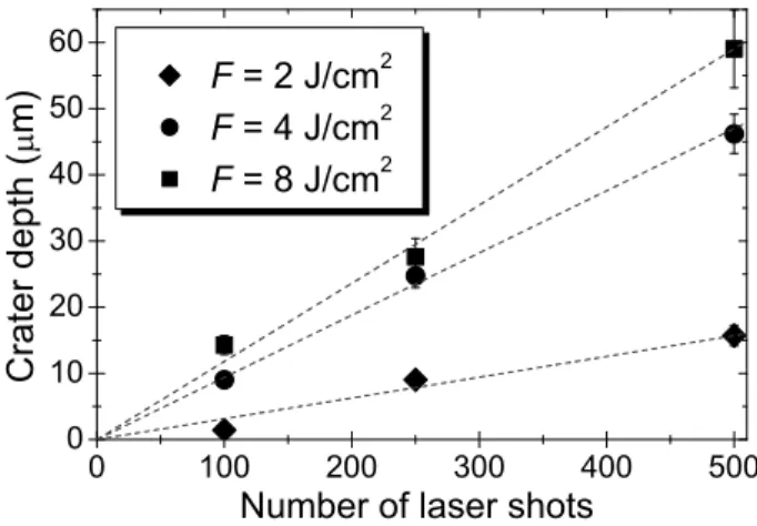
0 100 200 300 400 500 0 10 20 30 40 50 60 C r a t e r d e p t h ( m )
Number of laser shots F = 2 J/cm 2 F = 4 J/cm 2 F = 8 J/cm 2
FIG. 2: Crater depth as a function of a number of applied laser shots for different laser fluences F . Tore Supra graphite,
non-plasma-facing surface, λL = 532 nm, τp = 5 ns, νL =
20 Hz. Laser spot diameter is 1 mm.
may reduce LA rate and, thus, results in saturation of the crater depth dependence versus the laser fluence. The crater depth (Fig.2) was a linear function of the num-ber of applied laser pulses (up to 500 shots) when the resulting crater depth was much lower than the crater diameter.
For a low repetition rate heating (20 Hz), thermal en-ergy accumulation by the graphite surface from pulse to pulse was negligible. With each laser pulse, the sur-face LH re-commenced from the same ambient temper-ature T0 (room temperature). The important thermal
energy accumulation from pulse to pulse was expected for the high (10 kHz) repetition rate heating. As a re-sult, LA rates were expected to be significantly different for low and high repetition rate pulses of the same
du-0 1 2 3 4 5 6 7 0.00 0.02 0.04 0.06 0.08 0.10 0.12 0.14 0.16 0.18 0.20 C r a t e r d e p t h ( m / sh o t ) Laser fluence (J/cm 2 ) 100 ns 10 kHz 100 ns 20 Hz F th = 2.5 ± 0.5 J/cm 2
FIG. 3: (Color online) Crater depth (normalized to one laser shot) as a function of laser fluence. Tore Supra graphite,
non-plasma-facing surface, λL= 532 nm, τp= 100 ns, νL= 10 kHz
(H) and 20 Hz (N), 100 or 1000 laser shots per crater. Laser pulse energy is 6 mJ.
ration. However, the experimental results obtained with the backside surface of Tore Supra graphite samples did not support these estimations. For 100 ns laser pulses, no important difference in LA rates for νL of 20 Hz and
10 kHz was observed within the measurements accuracy (Fig. 3). 100 or 1000 pulses were applied to form the craters. For this number of pulses, the accumulated heat was expected close to maximum.
For 100 ns laser pulses, the linear dependences of the crater depth from the laser fluence and the number of ap-plied laser pulses were observed for low and high repeti-tion rates. The crater depth dependence on laser fluence can be approximated by a linear function (Eq. 1) with β ≈ 0.028 µm · cm2/J (Fig.3). The LA threshold F
thwas
2.5 ± 0.5 J/cm2for both repetition rates. This threshold
was 2.5 times higher than the one of ≈ 1 J/cm2 for 5 ns
laser pulses. The difference in the LA thresholds can be associated with the pulse durations. Amorphous reactor graphite can be referred to the matter with metal-like properties.20,21,25,26,27,28 For these samples, the ratio of
LA thresholds should be close to the square root from the ratio of the corresponding nanosecond pulse durations,32
that is, approximately 4.5 for our experiments. For Tore Supra graphite, the experimentally obtained threshold ratio of 2.5 can be associated with the sufficiently low laser absorption coefficient (at λL= 532 nm) in the
tem-perature range between the ambient T0 and sublimation
TStemperatures.
B. Simulations of laser ablation
To simulate LH/LA of a graphite surface, one should know thermal and optical properties of tokamak graphite in the temperature range above the ambient temperature T0 ≈ 300 K and below the graphite sublimation
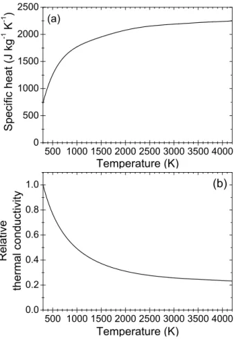
tem-500 1000150020002500300035004000 0 500 1000 1500 2000 2500 S p e c i f i c h e a t ( J k g -1 K -1 ) Temperature (K) (a) 500 1000150020002500300035004000 0.0 0.2 0.4 0.6 0.8 1.0 R e l a t i v e t h e r m a l c o n d u c t i v i t y Temperature (K) (b)
FIG. 4: Graphite thermal properties: (a) mass specific heat and (b) relative thermal conductivity (with respect to thermal
conductivity at T0= 300 K).
perature TS ≈ 4200 K. The graphite tiles density of
ρG ≈ 1700 kg/m3 is typical for manufactured graphite
in nuclear industry.20 The natural graphite density is
ρ0 ≈ 2240 kg/m3.20,21 Thus, for tokamak graphite tiles,
the mean porosity pG ≈ 25%.20
Mass specific heat of graphite (Fig. 4a) is a temper-ature dependent parameter.20,21,33 The mean mass
spe-cific heat is c0 ≈ 1500 J/(kg · K). Knowing the graphite
tile porosity, the mean volume specific heat of Tore Supra graphite is estimated as cG = (1 − pG)ρ0c0 ≈
2.5 MJ/(m3· K). The graphite thermal conductivity
k(T0) at room temperature should be considered as an
adjusting parameter due to the scatter in the data on this parameter.20,21,25,26,27,28 The temperature
depen-dent relative thermal conductivity k(T )/k(T0) is
avail-able from Ref.20(Fig.4b). Thermal conductivity k(T0)
of mono-crystal natural graphite at room temperature may vary in 2 − 2000 W/(m · K) range for different direc-tions to crystal axes.21 For amorphous Tore Supra
toka-mak graphite, k(T0) = 120 W/(m · K) was obtained by
fitting the LH and LA experimental results with the cal-culations. The obtained value is in a good agreement with the thermal conductivity of Tore Supra graphite26
(CEA Cadarache, France), with the data in Ref.14, and close to the thermal conductivity of some metals.21Thus,
the mean thermal conductivity of tokamak graphite in 300 − 4200 K temperature range is kG ≈ 60 W/(m · K)
(Fig.4b).
Graphite can be referred to semi-metals34with the
no-ticeable dependence of the laser absorption coefficient on temperature. To our knowledge, the temperature de-pendences of graphite optical properties are not avail-able in literature. At λL = 532 nm, laser absorption
coefficient and reflectivity of natural dense graphite at room temperatures can be obtained from the experi-mental data of Ref. 27. The determined absorption coefficient is α0(T0) ≈ 34 µm-1. For porous tokamak
graphite, the absorption coefficient can be estimated as α(T0) = (1 − pG)α0(T0) ≈ 25 µm-1. These values are
close to the typical metal absorption coefficients. The reflectivity of natural dense graphite at room tempera-ture is estimated as R0 ≈ 0.29. The reflectivity RG of
the tokamak graphite is low due to porosity. The linear approximation on graphite density for both the refrac-tive index and the absorption coefficient can be applied. Thus, RG≈ 0.22. Graphite reflectivity does not strongly
depend on temperature, as it is mainly determined by polarizability of ion cores, rather than free electrons.34
Heating depth is proportional to (DGτp)1/2, where
DG = kG/cG ≈ 0.24 cm2/s is the mean thermal
dif-fusivity of graphite, and τp is pulse duration. For the
same laser fluence, the longer the laser pulse duration is, the deeper the heat penetration and the lower the heating temperature. Thus, LA threshold Fthshould
de-pend on the laser pulse duration as τp1/2, if the
heat-ing depth is much higher than the laser absorption length. This threshold dependence is well known for the metal heating by nanosecond laser pulses32 with the
surface heating temperature ∆T ≡ T − T0 = {2(1 −
RG)/(πcGkG)1/2)}F/τp1/2 reached by the end of laser
heating pulses (for the rectangular pulse heating model). This is the case of “surface heating regime” (in contrast to “volume heating regime” where ∆T does not depend on τp32,35,36). For surface heating regime, the additional
condition (DGτp)1/2 ¿ r0 should be satisfied (r0 is the
radius of the laser spot on the surface). This condition was always met in our LA experiments with r0∼ 500 µm.
From the available data on natural graphite, the ab-sorption length at λL = 532 nm at room temperature is
less than 0.1 µm. The heat penetration depth is ∼ 1 µm for laser pulses applied in our experiments. Thus, for 100 ns and 5 ns pulses, the LA thresholds ratio should be close to (100/5)1/2 ≈ 4.5. This would be true, if
the absorption length of laser radiation were much lower than the thermal diffusion length for both pulse dura-tions. The low thresholds ratio of 2.5 obtained in the experiments with Tore Supra graphite can be associated with the increase in the laser absorption length with the temperature increase up to TS. In this case, the
strong inequality α−1G ¿ (DGτp)1/2 is violated (mostly
for 5 ns pulses). Thus, the square root dependence for
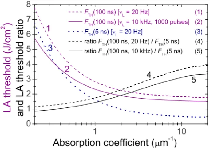
1 10 0 1 2 3 4 5 6 7 8 5 4 2 3 1 F TH (100 ns) [ L = 20 Hz] (1) F TH (100 ns) [ L = 10 kHz, 1000 pulses] (2) F TH (5 ns) [ L = 20 Hz] (3) ratio F TH (100 ns, 20 Hz) / F TH (5 ns) (4) ratio F TH (100 ns, 10 kHz) / F TH (5 ns) (5) L A t h r e s h o l d ( J / c m 2 ) a n d L A t h r e s h o l d r a t i o Absorption coefficient ( m -1 )
FIG. 5: (Color online) Calculated LA thresholds of tokamak graphite for 5 ns (20 Hz repetition rate) and 100 ns laser pulses (20 Hz and 10 KHz repetition rate) and ratio of LA thresh-olds as a function of the mean absorption coefficient of the graphite.
surface temperature, that is valid only for “surface heat-ing regime”, can not be applied. For the other limitheat-ing case with α−1
G À (DGτp)1/2 (“volume heating regime”),
the surface temperature does not depend on the pulse duration, and the LA thresholds would be the same for both 5 ns and 100 ns laser pulses.
The dependences of LA thresholds and their ratios ver-sus αG (Fig.5) were calculated by the developed 3D LH
model (Appendix A) with mean constant graphite pa-rameters. The LA thresholds were determined for rec-tangular laser pulses that heated the graphite surface up to the sublimation temperature TS. For 100 ns laser
pulses, the laser beam was of 6 mJ pulse energy. Laser fluence was adjusted by varying the laser spot diame-ter. For 5 ns pulses, with the fixed radius r0 = 500 µm,
laser fluence was adjusted by the pulse energy. For τp = 100 ns (for both νL of 20 Hz and 10 kHz) and
τp = 5 ns (for νL = 20 Hz), the experimentally obtained
ablation thresholds and their ratios can be explained the-oretically only if we accept the sufficiently low mean ab-sorption coefficient αG= 2 µm-1 of tokamak graphite at
λL= 532 nm. This value is used in our calculations, as it
gives the best fit for the experimental results. For dense graphite (with zero porosity), the mean laser absorption coefficient is α0≈ αG/(1 − pG) ≈ 2.67 µm-1.
The difference in the theoretical LA thresholds for graphite at τp= 100 ns for high (10 kHz) and low (20 Hz)
repetition rates (Fig.5) may be associated with thermal energy accumulation by the surface from pulse to pulse at 10 kHz repetition rate. For a high repetition rate, the sur-face cooling between two subsequent pulses is not com-plete. The residual heating temperature is permanently increasing with the number of applied pulses until it reaches the stable value ∆T?. Based on the heat equation solution,35,36the time t? required to reach the tempera-ture ∆T?is estimated from (D
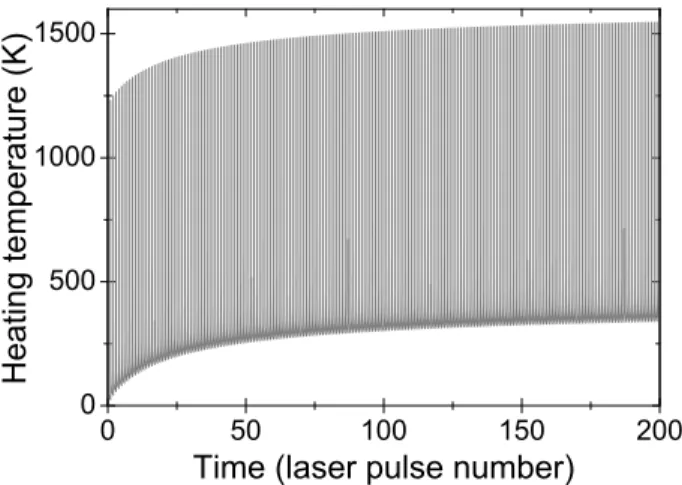
0 50 100 150 200 0 500 1000 1500 H e a t i n g t e m p e r a t u r e ( K )
Time (laser pulse number)
FIG. 6: Calculated profile of the surface heating temperature
∆T = T − T0 of the tokamak graphite (with the above
pa-rameters) at heating by 200 laser pulses of 10 kHz repetition
rate and 100 ns pulse duration. T0 is ambient temperature.
Laser fluence F = 0.7 J/cm2.
estimated from ∆T? ≈ 0.5F (1 − R
G)r0νLπ1/2/kG. This
expression corresponds to CW LH with the power equal to the average one of the pulsed laser with the repetition rate νL. For the heating time t À t?, LH starts from the
surface temperature T0+ ∆T?. For tokamak graphite
with the above thermal parameters and r0≈ 522 µm, t?
corresponds to ≈ 100 laser pulses, and the pre-heating temperature ∆T? ≈ 420 K for F = 0.7 J/cm2 and
νL = 10 kHz is reached with a few hundred laser pulses.
The 3D analytical model of LH (AppendixA) was ap-plied to calculate the temperature profile for 200 laser pulses (Fig.6). For a high repetition rate (10 kHz) and a sufficient number of applied laser pulses, the pre-heating effect reduced the LA threshold. For a low repetition rate (νL= 20 Hz), the pre-heating is negligible. The LA rates
of tokamak graphite were calculated with the developed Stefan-like model for LA of sublimating/evaporating ma-terials (Appendix B). The model is based on the nu-merical solution of the 1D heat equation with the Ste-fan boundary condition.32,37 The 1D approach (on a
single-shot time scale) is relevant for our experimental conditions. The pre-heating effect may be important for a high repetition rate and a high number of laser shots applied for crater formation. It was incorporated in the LA model phenomenologically. The temperature dependences of specific heat and thermal conductivity of graphite (Fig. 4) were taken into account in the LA model. Other parameters were taken as mean constant values. Mass specific heat of sublimation was taken as 50 MJ/kg from Ref. 20. Figure 7 presents LA rates for the temporal shape of the laser pulse of sin2(πt/2τ
p)
(0 ≤ t ≤ 2τp). The calculated crater depth
depen-dences on laser fluence near the LA thresholds are not linear. This may explain the fact that the theoretical LA threshold is slightly lower than the one defined by the linear fit of the experimental ablation depths. A good
0 1 2 3 4 5 0.00 0.05 0.10 0.15 0.20 the experimental data zone for 100 ns pulses Calculations: 5 ns 20 Hz 100 ns 20 Hz 100 ns 10 kHz A b l a t i o n d e p t h ( m / s h o t ) Laser fluence (J/cm 2 ) the experimental data zone for 5 ns pulses
FIG. 7: Calculated and experimental ablation rates of Tore
Supra graphite sample versus laser fluence (see Fig.1for
ex-perimental results for 5 ns pulses at 20 Hz repetition rate and
Fig.3for 100 ns pulses at 20 Hz and 10 kHz repetition rates).
agreement between the calculated and experimental LA rates was obtained for 5 ns laser pulses (νL = 20 Hz) for
laser fluences below 3.5 J/cm2. For higher laser fluences,
the experimental LA rates are lower than the theoretical ones. It may be associated with the plasma screening of 5 ns laser beam. The screening effect was not consid-ered in the LA model, which was developed for threshold determination.
For 100 ns laser pulses, the calculation and experimen-tal results are in agreement only near the LA thresh-old. For higher laser fluences, the difference between the calculation and experimental results may be associated with the laser beam screening (diffusion) by the ablation products (micro particles). At different repetition rates (20 Hz and 10 kHz), the pronounced difference between the theoretical LA rates (Fig. 7) may be attributed to the different intensity of heat accumulation. Within the measurement accuracy, this difference was not observed experimentally.
The quantitative agreement between the theoretical and experimental results near ablation thresholds for both pulse durations has validated the applicability of the developed LA model to tokamak graphite with the thermal and optical parameters specified above.
III. HIGH REPETITION RATE LASER
HEATING OF TORE SUPRA GRAPHITE
A. Experimental results
The experimental pyrometer system based on an Impac-Kleiber C-LWL infra-red pyrometer was devel-oped in our laboratory to study high repetition rate LH. The pyrometer system parameters were as follows: 600 − 2600 K temperature range, 1.6 − 2.2 µm working
0 50 100 150 200 0 500 1000 1500 H e a t i n g t e m p e r a t u r e ( K )
Time (laser pulse number) 9 10 11 12 0 500 1000 1500 (a) 0 50 100 150 200 0 500 1000 1500
Theory: the pre-heating temperature Theory: the peak heating temperature
H e a t i n g t e m p e r a t u r e ( K )
Time (laser pulse number) 91 92 93 94 0 500 1000 1500 (b)
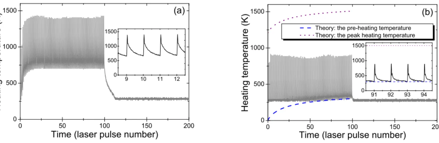
FIG. 8: (Color online) Panel (a) - experimental results on high repetition rate (10 kHz) LH of the non-plasma-facing surface
of Tore Supra graphite by 100 laser pulses at laser fluence F = 0.62 J/cm2. Panel (b) - LH measurements at laser fluence
F = 0.7 J/cm2for the same surface, but pre-processed by LA. Theoretical data for pre-heating and peak heating temperatures
(see Fig.6) are presented by the dash and dot curves, respectively. The surface heating temperature is ∆T = T − T0, T0 is
ambient temperature.
wavelength range, 15 µs response time (t99%).
The simulation results on LH of graphite surface by 100 ns laser pulses at νL= 10 kHz and 0.7 J/cm2laser
flu-ence (Fig.6) were taken as the reference point in the py-rometer measurements of tokamak graphite temperature. The measured temperature was expected close to the one of Fig.6. But the experimental temperatures were quite different (Fig.8a). For 0.62 J/cm2 laser fluence, the
pre-heating temperatures were higher than expected. The time t? required to reach the pre-heating temperature saturation ∆T? was ten times less than the theoreti-cal one estimated from the specified tokamak graphite parameters and was corresponding to ten laser pulses. The pre-heating temperatures were extraordinarily sta-ble from approximately the 15th laser pulse. A number
of LH simulations were made to obtain the experimental temperature profile (Fig. 8a). Nevertheless, the simu-lation efforts were not successful, even with the signifi-cantly modified graphite parameters.
A hypothesis on a thin (micrometer) boundary layer on the graphite surface with the properties different from those of the bulk graphite was suggested to explain the experimental results. During the initial LH by the first ten laser pulses, the surface temperature increases signif-icantly due to the reduced thermal conductivity of the layer. When the heating depth becomes higher than the layer thickness, the bulk graphite properties are the main factors, which slow down the pre-heating temperature in-crease. The preliminary results on the modelling with this hypothesis in mind are presented in Ref.30,31. The physical nature of this layer is not yet clear. As the graphite was not exposed to plasma, the layer forma-tion might be due to mechanical cutting in manufactur-ing tokamak graphite tiles.
To check the boundary layer hypothesis, LH was per-formed on a surface area, which was pre-processed by
LA. A thin layer of 4 ± 2 µm depth was removed from the surface by LA. The pyrometer temperature trace from the pre-processed area (Fig.8b) did not reproduce the temperature profile of Fig. 8a, but was similar to the theoretical one for the bulk graphite (Fig.6). The com-parison of the theoretical and experimental results was not able to confirm the LH trace of the pre-processed graphite surface (Fig. 8b) due to a long 15 µs response time of the pyrometer, that is, 150 times longer than 100 ns laser pulse duration. Thus, the actual peak heat-ing temperature reached on the pulse duration scale can not be measured by the pyrometer, and it should be higher than the experimental peak temperature. As the low temperature limit of the pyrometer is about 600 K, it is not possible to measure the whole temperature profile for the pre-processed surface. For LH by 100 laser pulses at 0.7 J/cm2 fluence, the pre-heating temperatures are
slightly above 600 K only from the 60th laser pulse. The
pre-heating temperature depends on the adjusting pa-rameter of thermal conductivity coefficient, rather than on laser absorption coefficient. The latter affects only the peak heating temperature. From the comparison of the pyrometer measurements with the theoretical data, the mean thermal conductivity for tokamak bulk graphite was determined as 60 W/(m · K).
B. Simulations of graphite laser heating and
characterization of surface layer
The extraordinary stability of the experimental pre-heating temperature from the 15th laser pulse (Fig.8a)
may be associated with LA of a thin layer on the surface even at 0.62 J/cm2 laser fluence. During LA, the peak
surface temperature should be the same as the graphite sublimation temperature TS. After each laser pulse
ap-0 5 10 15 20 0 700 1400 2100 2800 3500 H e a t i n g t e m p e r a t u r e ( K )
Time (laser pulse number) Calculation Experiment (a) 0 5 10 15 20 0 700 1400 2100 2800 3500 H e a t i n g t e m p e r a t u r e ( K )
Time (laser pulse number) Calculation Experiment (b)
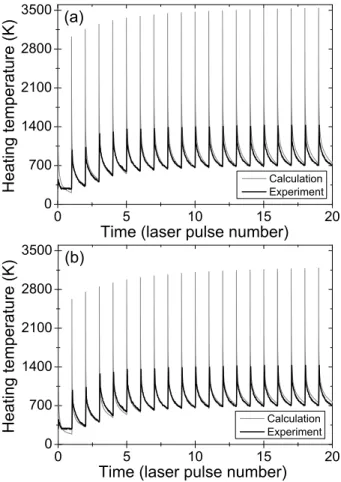
FIG. 9: Calculated high repetition rate (10 kHz) LH of graphite surface with the layer (with the properties different from those of bulk graphite) and experimental results from Fig.8a for the first twenty laser pulses. Panel (a) - calculated
results for pL = 25%, d = 8 µm, kL = 0.75 W/(m · K), and
h = 140 kW/(m2· K). Panel (b) - calculated results for p L=
0, d = 6 µm, kL= 0.75 W/(m · K), and h = 90 kW/(m2· K).
Laser fluence F = 0.62 J/cm2. The surface heating
tempera-ture is ∆T = T − T0, T0 is ambient temperature.
plication, the surface cooling starts from this TS. The
minimal temperature by the end of cooling (before next pulse application) should be the same for all repetitive laser pulses. Thus, the significant stability of the pre-heating temperature might be explained by LA.
The upper working temperature limit of the pyrometer is 2600 K. If the surface temperature is above, the cor-rect pyrometer measurements may be disturbed by the pyrometer photocurrent saturation. Thus, only the ini-tial non-saturated part of the LH trace may be referred to compare the experimental and simulation results.
The initial part of the LH trace (before pre-heating temperature stabilization) can be fitted with three ad-justing parameters. The pre-heating temperature profile (magnitude and curvature) can be adjusted by two pa-rameters. The third parameter can be used to adjust the cooling curve between two consecutive laser pulses. For a given layer porosity pL, three adjusting parameters
are the layer thickness d, the layer thermal conductivity kL, and the heat transfer coefficient h (layer adhesion
quality) on the interface between the layer and the bulk graphite (Eq. (A4), AppendixA). The layer heat capacity and the coefficients of layer light absorption and reflec-tion can be obtained from pL and bulk graphite
parame-ters. Figure9a presents the fit for pL = 25%. The best
fit was obtained with d = 8 µm, kL = 0.75 W/(m · K),
and h = 140 kW/(m2· K).
The heating temperature of a thin layer is determined by the layer heat capacity (per unit of surface) that is proportional to the product of the layer thickness and the layer specific heat, which, in turn, is proportional to the layer density. Thus, the layer heating temper-ature depends on the product d(1 − pL). Keeping the
product constant, but varying pL, it is possible to
ob-tain a good fit between the calculation and experimen-tal results for other values of d and pL. For example,
the agreement between the experiment and calculation data (Fig.9b) was also obtained with the following pa-rameters: pL = 0, d = 6 µm, kL = 0.75 W/(m · K), and
h = 90 kW/(m2· K). The layer thermal conductivity k L
of 0.75 W/(m · K) is the same as for the case of Fig.9a. This value was unexpectedly lower than the thermal con-ductivity of the bulk tokamak graphite, but it was the only one that provided the agreement between the ex-perimental and theoretical results in the cooling curve between two consecutive laser pulses.
To characterize the layer thickness of the backside Tore Supra (Fig.8a), the layer porosity should be known. If the porosity of the layer and the bulk graphite is the same, the layer thickness should be 8 µm. For pL >
25%, the expected layer thickness would be higher than 8 µm. This layer thickness estimation does not corre-spond to the measurements of the removed layer thick-ness (4 ± 2 µm) made with an optical microscope. Only for pL < 25%, the layer depth is 7 ± 1 µm. Thus, pL
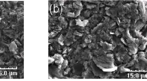
close to zero should be accepted in the calculations. The graphite tile manufacturing deteriorates the heat cou-pling of the porous graphite micro crystals on the tile surface, but does not affect the mean graphite density. It might also reduce the layer thermal conductivity. The mechanical cutting of graphite might cause its pulveriza-tion. Then, the graphite pores might be filled with sub-micrometer graphite dust. Figure10 presents the scan-ning electron microscopy (SEM) images of the backside surface of Tore Supra graphite tile. A strong roughness of the graphite surface is observed both before and after LA. Nevertheless, some difference in granularity is no-ticeable. It is smoother for the surface without the laser pre-treatment (Fig. 10a). This can testify to a higher friability of the surface layer.
IV. CONCLUSION
The experimental results on LA and LH of the back-side non-plasma-facing surface of tokamak graphite tiles
FIG. 10: SEM images of the backside non-plasma-facing surface of Tore Supra graphite tile before (a) and after (b) pre-processing by LA. The measured ablation depth is 4 ± 2 µm.
are presented. Two laser benches equipped with the py-rometer system for the temperature measurements were developed for our investigations. For 5 ns and 100 ns laser pulses at λL = 532 nm, the graphite LA thresholds were
determined as 1.0 ± 0.5 J/cm2 and 2.5 ± 0.5 J/cm2,
re-spectively.
The theoretical models of high repetition rate LH and near-threshold LA of complex surface (substrate with an intermediately adhered layer) were developed to simulate the experimental results and to character-ize tokamak graphite. The mean thermal conductiv-ity kG = 60 W/(m · K) of tokamak bulk graphite was
obtained by comparing the calculated and experimen-tal results on high repetition rate (10 kHz) LH of the graphite surface pre-processed by LA. The experimen-tally obtained LA thresholds for different pulse durations (5 ns and 100 ns) were applied to determine the graphite absorption coefficient. The absorption coefficient of toka-mak graphite (averaged over temperature between T0and
TS) at λL= 532 nm was estimated as 2 µm-1. This value
is unexpectedly low, especially considering the metal-like properties of graphite under normal conditions.
The experimental and calculated LA thresholds and rates of graphite tiles were compared. The good theoret-ical fit with the experimental results justified the sub-limation/evaporation mechanism of nanosecond LA of tokamak graphite.
The high repetition rate LH measurements on the non-plasma-facing surface of Tore Supra graphite were made with the developed pyrometer system. The temperature traces were significantly different from those expected from thermal and optical properties for tokamak bulk graphite. A hypothesis on a micrometer layer on the surface of manufactured graphite was suggested to ex-plain the obtained results. The layer properties were dif-ferent from those of tokamak bulk graphite. The layer hypothesis was supported by the LH experiments when
the layer was removed by LA from the surface. The ex-perimental temperature trace for the ablated graphite surface corresponded to the theoretical one determined for bulk graphite with the properties specified for toka-mak graphite. Thus, the surface layer hypothesis was confirmed by this experiment.
The simulations of the temperature traces obtained by the high repetition rate LH of the graphite with a surface layer allowed to adjust some unknown layer parameters. The layer parameters (porosity, thickness, thermal con-ductivity and heat transfer coefficient on the layer/bulk interface) may be determined from the fit of the simu-lation and experimental results. Thus, the method to characterize the surface layer was developed in our inves-tigations.
The deposited layer LA and LH were also under inves-tigation. A significantly low LA threshold of 0.5 J/cm2
was obtained for the plasma-facing surface with a thick (several tens of microns) deposited carbon layer (TEX-TOR tokamak tile, Garching, Germany). The deposited layer LA threshold was the same for 5 ns and 100 ns pulses. A 5-fold difference in the 100 ns LA thresholds for the deposited layer and graphite may provide LA clean-ing of the contaminated surface with deposited carbon layer without graphite substrate damage. The discus-sion on the results on the deposited layer LA and LH is beyond the scope of this paper and will be presented somewhere else.
ACKNOWLEDGMENTS
The authors are grateful to Mrs. C´ecile Blanc for SEM measurements and to Mr. Miguel Do Nascimento for as-sistance in refinement of the LA data. This work was per-formed within the frames of the Euratom - CEA underly-ing technological program, task UT–S&E–LASER/DEC.
APPENDIX A: 3D LASER HEATING MODEL OF THE SURFACES WITH A LAYER
We suppose the normal incidence of the laser beam on the surface along the z-axis. The heat equations for LH of the surface with a layer for temperature distribution T (t, r) are the following:
cL
∂T
∂t = div(kL∇T ) + QL(t, r) (0 < z < d) , (A1) cS∂T
∂t = div(kS∇T ) + QS(t, r) (z > d) , (A2) where d is layer thickness, cL(T ) and cS(T ) are volume
specific heats and kL(T ) and kS(T ) are coefficients of
thermal conductivity of the layer and the substrate, re-spectively, and QL(t, r) and QS(t, r) are LH source terms
due to absorption of the laser radiation in the layer and, if occurs, in the substrate. The boundary condition should reflect the continuity of the thermal energy flux through the layer/substrate interface z = d:
−kL ∂ T ∂ z ¯ ¯ ¯ ¯ d−0 = −kS ∂T ∂z ¯ ¯ ¯ ¯ d+0 ≡ qd. (A3)
Extra boundary condition relating the temperature jump and the heat flux on the interface z = d is introduced phenomenologically, with the positive heat transfer coef-ficient h:
∆Td≡ T |z=d−0− T |z=d+0= qd/h . (A4)
Eq. (A4) reflects the thermal resistance of the contact be-tween the layer and the substrate. In two limiting cases of h → 0 and h → ∞ we obtain either a completely im-perfect or completely im-perfect heat contact, respectively. With nanosecond LH, the convective and radiation losses on external boundary z = 0 can be neglected. Thus, the condition ∂T /∂z|z=0= 0 was used. The initial condition in Eqs. (A1) - (A2) is taken as T |t=0= T0, where t = 0
is the time of LH onset.
The LH source terms QL(t, r) and QS(t, r) can be
deduced from macroscopic electrodynamics.38 They are
proportional to laser intensity space-time distribution I(t, r⊥). Here, r⊥ means either Cartesian coordinates x and y in the plane z = 0 or polar coordinates r and ϕ. The Cartesian coordinates are preferable for the moving laser beam scanning the surface. Func-tion I(t, r⊥) can be presented in a factorized form as I(t, r⊥) = I0fXY(x − vt, y)fT(t) , where I0 is either the
steady-state or the peak laser intensity (for continuous or pulsed lasers, respectively), v is laser scanning veloc-ity along the x-axis, and the dependences on r⊥and on t are separated with fXY(x, y) and fT(t) functions nor-malized to unity in the maximum. Consequently, the LH source terms are also separated:
QL(t, r) = fZL(z)fXY(x − vt, y)fT(t), QS(t, r) = fZS(z)fXY(x − vt, y)fT(t), with fL Z(z) = I0ωε 00 L 4c ¯ ¯ ¯ eC ¯ ¯ ¯2 ¯ ¯ ¯1 +pεS/εL ¯ ¯ ¯2e−αLd × ¯ ¯ ¯ ¯ ¯e iω√εL(z−d)/c+1− p εS/εL 1+pεS/εL eiω√εL(d−z)/c ¯ ¯ ¯ ¯ ¯ 2 , (A5) fZS(z) = I0 ωε00 S c ¯ ¯ ¯ eC ¯ ¯ ¯2eαS(d−z)−αLd, (A6) e C = 4 n (1 +√εL) ³ 1+pεS/εL ´ e−iωdnL/c + (1−√εL) ³ 1−pεS/εL ´ eiωdnL/c−αLd o−1 . Here, c is the light velocity, ω is the laser frequency, εL
and εS are the complex dielectric permittivities of the
layer and the substrate, respectively, ε00
L and ε00S are their
imaginary parts related with respective absorption co-efficients by αL = ωε00L/cnL and αS = ωε00S/cnS, with
nL = Re¡√εL
¢
and nS= Re¡√εS
¢
the refraction coeffi-cients of the laser light in the boundary layer and in the substrate. The light reflection coefficients (RL and RS)
on the interfaces between the corresponding medium and ambient air are expressed through the respective dielec-tric permittivity.38 If the layer thickness d is higher than
the laser wavelength, we can average the source term QL(t, r) over the laser field spatial oscillations. The
av-eraged source term QL(t, r) can be expressed as:
fZL(z) → fZL(z) = I0ωε 00 L 4c ¯ ¯ ¯ eC ¯ ¯ ¯2 ¯ ¯ ¯1 +pεS/εL ¯ ¯ ¯2 × e −αLz+ ¯ ¯ ¯ ¯ ¯ 1−pεS/εL 1+pεS/εL ¯ ¯ ¯ ¯ ¯ 2 eαL(z−2d) . (A7)
As thermal and optical parameters depend on temper-ature, the direct numerical solution of Eqs. (A1) - (A2) in 3D-space and time for high repetition rate LH be-comes a baffling problem even for moderate computers. It was verified and proved that, for graphite, the exact and the approximate analytical solutions are the same within the pyrometer temperature measurements accu-racy. This analytical solution with the constant (mean) matter parameters was used. The final result for the heating temperature ∆T (t, r) ≡ T (t, r)−T0in the
Carte-sian coordinates was obtained by the Fourier method.39
It can be presented as: ∆T (t, r) = Z Z +∞ −∞ dλxdλy (2π)2 Φ(λx, λy)e i (xλx+ yλy) × +∞ Z 0 2dλz π Θ(λx, λy, λz, t)Ψ(λr, λz)Zλz(z) + N (λXr) n=1 Θn(λx, λy, t)Ψn(λr)Zχn(z) , (A8)
where λr=qλ2
x+ λ2y, and Zλz(z) and Zχn(z) are
eigen-functions of relevant boundary problem for continuous and discrete spectrum of eigenvalues λz and χn, respec-tively. In Eq. (A8), the different functions are defined as: Φ(λx, λy) = Z Z +∞ −∞ e−i (xλx+ yλy)f XY(x, y) dxdy , Θ(λx, λy, λz, t) = Z t 0 e−ivλxt0f T(t0)eDS(λ 2 r+ λ2z)(t0− t)dt0, Θn(λx, λy, t) = Z t 0 e−ivλxt0f T(t0)eDS(λ 2 r− χ2n)(t0− t)dt0, Ψ(λr, λz) = 1 cS Z +∞ 0 dz fZ(z) Zλz(z) , Ψn(λr) = 1 cS Z +∞ 0 dz fZ(z) Zχn(z) .
Here and after, DL = kL/cL and DS = kS/cS are the
thermal diffusivity coefficients of the layer and the sub-strate, respectively, and fZ(z) = fL
Z(z) at 0 < z < d and fZ(z) = fZS(z) at z > d. The above integrals might be ex-pressed analytically. Function Φ(λx, λy) is defined by the spatial distribution of the laser intensity. It may be sim-plified for the Gaussian and homogeneous intensity distri-butions. In the latter case Φ(λx, λy) = 2πr0J1(r0λr)/λr,
where r0 is the radius of a circular laser spot and J1(x)
is the Bessel function.
Functions Θ(λx, λy, λz, t) and Θn(λx, λy, t) are defined by the time dependence of the laser intensity. They may be simplified both for continuous and pulsed lasers with rectangular pulses or sin2-pulses. For rectangular pulses
with duration τp and repetition rate νL (fT(t) = 1 at
m/νL < t < τp+ m/νL, m = 0, 1, 2, . . . , otherwise
fT(t) = 0), the continuous spectrum Θ-function is ex-pressed as: Θ(λx, λy, λz, t) = exp (−iλxvt) × (eΛzm/νL − 1)(eΛzτp − 1)e−Λzt (eΛz/νL − 1)Λz + 1 − eΛz(m/νL− t) Λz , (eΛz(m+1)/νL − 1)(eΛzτp − 1)e−Λzt (eΛz/νL − 1)Λz ,
where Λz= DS(λ2r+ λ2z) − ivλx, upper line corresponds to m/νL < t < m/νL+ τp (during the pulses) and lower
line corresponds to m/νL+τp< t < (m+1)/νL(between
the pulses). The function Θn(λx, λy, t) can be obtained by substitution Λz→ Λn= DS(λ2r− χ2n) − ivλx.
To express explicitly functions Ψ(λr, λz) and Ψn(λr) defined by the z-dependence of the LH source terms, one should know eigenfunctions of the boundary prob-lem, Zλz(z) and Zχn(z). For arbitrary eigenvalue λz,
eigenfunction Zλz(z) satisfies the equations: Zλ00z = −[(λ 2 r+ λ2z)DS/DL− λ2r] Zλz (0 < z < d) , (A9) Zλ00z = −λ 2 zZλz (z > d) , (A10)
with the boundary conditions Zλz|d−0 − Zλz|d+0 = −(kL/h)Z0λz|d−0, kLZ 0 λz|d−0 = kSZ 0 λz|d+0, Z 0 λz|z=0 =
0 . For the heating of the surface with a layer, the eigen-value spectrum contains both the continuous and discrete parts. The continuous spectrum corresponds to real val-ues of λz. In this case, the solution of Eqs. (A9) - (A10) is: Zλz(z) = cos(λz) √ A2+ B2 (0 < z < d) , Zλz(z > d) = A sin(λzz) + B cos(λzz) √ A2+ B2 , where λ =p(λ2 r+ λ2z)DS/DL− λ2r, and A = p sin(λzd) − kLλ kSλzcos(λzd) sin(λd) , B = p cos(λzd) + kLλ kSλzsin(λzd) sin(λd) ,
with p = cos(λd) − (kLλ/h) sin(λd). For the discrete set
of eigenvalues, with pure imaginary values of λz = iχ (χ > 0), the set of eigenvalues will be defined as χn with n = 1, 2, . . . . Then, eigenfunctions Zχn(z) of the discrete
spectrum have the form:
Zχn(z) = ancos (λnz) (0 < z < d) , Zχn(z > d) = an µ cos(λnd) −kLλn h sin(λnd) ¶ e−χn(z−d), where λn =p(λ2 r− χ2n)DS/DL− λ2r, an is the normal-ization constant, and the χn-value should satisfy the equation:
λntan (λnd) = hkSχn kL(h + kSχn)
. (A11)
For DS/DL≤ 1, Eq. (A11) for each value of λrhas no
so-lutions. Thus, the discrete spectrum does not exist. For DS/DL> 1, the discrete spectrum is always present
(ex-cept for the 1D model, where λr= 0). For each nonzero λr the solutions belong to 0 < χn < λr
p
1 − DL/DS,
when λn is real, and the number of solutions increases with increasing λr. If N (λr) ≥ 1 defines the total finite number of solutions of Eq. (A11) for the given λr, χn(λr) defines the discrete eigenvalue for 1 ≤ n ≤ N (λr).
By integrating over z, the expressions for functions Ψ(λr, λz) and Ψn(λr) are obtained:
Ψ(λr, λz) = (˜a(+)− ˜a(−)e−2dαL)αL cS(λ2+ αL2)
√
A2+ B2
+(˜a
(+)+ ˜a(−))λ sin(λd) − (˜a(+)− ˜a(−))α
Lcos(λd)
edαLcS(λ2+ α2
L)
√
A2+ B2
+˜b{(AαS− Bλz) sin(λzd) + (BαS+ Aλz) cos(λzd)} edαLcS(λ2
z+ α2S)
√
Ψn(λr) =an(˜a
(+)− ˜a(−)e−2dαL)α
L
cS(λ2n+ α2L)
+(˜a
(+)+˜a(−))λnsin(λnd)−(˜a(+)−˜a(−))α
Lcos(λnd) edαLcS(λ2 n+ αL2)a−1n +˜b{cos(λnd) − (kLλn/h) sin(λnd)} edαLcS(χn+ αS)a−1n , where ˜a(±)= I 0ω ε 00 L 4c ¯ ¯ ¯ eC ¯ ¯ ¯2 ¯ ¯ ¯1 ±pεS/εL ¯ ¯ ¯2, ˜b = I0ωε 00 S c ¯ ¯ ¯ eC ¯ ¯ ¯2. These expressions present the analytical solution of the LH of the surface with a boundary layer and with in-termediate heat contact between the layer and the sub-strate, in the rectangular geometry for the general case of scanning pulsed laser beam. The simplified version of this solution can be obtained in the cylindrical geometry with circular symmetry of the laser spot and immobile laser beam. In this case, the heating temperature is ex-pressed by: ∆T (t, r, z) = Z +∞ 0 dλrΦ(λr)J0(rλr) × ½Z +∞ 0 2 dλz π Θ(λr, λz, t)Ψ(λr, λz)Zλz(z) +XN (λr) n=1 Θn(λr, t) Ψn(λr) Zχn(z) ¾ ,
where v = 0 should be used in the corresponding expres-sions for Θ-functions. For homogeneous laser intensity distribution, Φ(λr) = r0J1(r0λr) should be applied.
APPENDIX B: 1D LASER ABLATION MODEL OF SUBLIMATING MATERIALS
One-dimensional approximation is applied to consider LA on nanosecond time scale (for a single laser pulse)
with the spot diameter of ∼ 1 mm. Surface pre-heating by previous laser pulses can be taken into account by the initial condition T (t = 0, z) = T0+ ∆Tn∗(z), where T0 is the ambient temperature and ∆Tn∗(z) is the sur-face heating temperature just before the n-th laser pulse application. Saturation of the surface pre-heating tem-perature results from the finite size of the laser spot: ∆T∗
n(z = 0) → ∆T∗ at n → +∞. The calculations of ∆T∗
n(z) are made with the 3D LH model (AppendixA). If the laser fluence F is less than the ablation thresh-old Fth, the temperature field T (t, z) can be described
by the one-dimensional version of Eqs. (A1) - (A2). For the laser fluence F above the ablation threshold Fth, the
surface temperature should be higher than the sublima-tion temperature TS, if LA is not taken into account. For
F > Fth, three intervals for the laser beam interaction
with the surface may be distinguished.
For 0 < t < t1 with t1 < τp, the surface
temper-ature increases in time up to sublimation tempertemper-ature, so T (t, z = 0) < TS, with T (t1, z = 0) = TS. During
LA stage t1 ≤ t ≤ t2, the surface temperature should
be set equal to the sublimation temperature TS (t2 can
differ from τp, depending on the laser pulse shape and
difference F − Fth). In accordance with the energy
con-servation law,32,37 the Stefan boundary condition on the
moving external boundary of the surface is applied: kL(TS)∂T ∂z ¯ ¯ ¯ z=zA(t) = LρLvA(t) . (B1)
Here, L is the mass specific heat of sublimation, ρL is
the matter density, and vA(t) = dzA(t)/dt is the speed
of LA front. For t > t2, the surface temperature is lower
than the sublimation temperature, T (t, z = 0) < TS, and
the surface is not ablated. The LA depth H for the n-th laser pulse can be calculated through the self-consistently found speed of LA front as: H =Rt2
t1 vA(t)dt ≡ zA(t2).
1 I. Youle and A.A. Haasz, J. Nucl. Mater. 248, 64 (1997).
2 G. Federici, R.A. Anderl, P. Andrew, J.N. Brooks, R.A.
Causey, J.P. Coad, D. Cowgill, R.P. Doerner, A.A. Haasz, G. Janeschitz, W. Jacob, G.R. Longhurst, R. Nygren, A. Peacock, M.A. Pick, V. Philipps, J. Roth, C.H. Skinner, and W.R. Wampler, J. Nucl. Mater. 266–269, 14 (1999).
3 P. Andrew, D. Brennan, J.P. Coad, J. Ehrenberg, M.
Gade-berg, A. Gibson, M. Groth, J. How, O.N. Jarvis, H. Jensen, R. L¨asser, F. Marcus, R. Monk, P. Morgan, J. Orchard, A. Peacock, R. Pearce, M. Pick, A. Rossi, B. Schunke, M. Stamp, M. von Hellermann, D.L. Hillis, and J. Hogan, J. Nucl. Mater. 266–269, 153 (1999).
4 M. Friedrich, W. Pilz, G. Sun, R. Behrisch, C.
Garcia-Rosales, N. Bekris, and R.-D. Penzhon, Nucl. Instrum. and Meth. B 161–163, 216 (2000).
5 R.A. Causey, J. Nucl. Mater. 300, 91 (2002).
6 T. Tanabe, N. Bekris, P. Coad, C.H. Skinner, M. Glugda,
and N. Miya, J. Nucl. Mater. 313–316, 478 (2003).
7 C.H. Skinner, J.P. Coad, and G. Federici, Physica Scripta
T111, 92 (2004).
8 C.H. Skinner, H. Kugel, D. Mueller, B.L. Doyle, and W.R.
Wampler, Tritium Removal by CO2 Laser Heating,
Pro-ceedings of the 17th IEEE/NPSS Symposium on Fusion
Engeneering (SOFE’97, 6–9 October 1997, San Diego, USA), vol.1, 321–324 (1998).
9 C.H. Skinner, C.A. Gentile, A. Carpe, G. Guttadora, S.
Langish, K.M. Young, W.M. Shu, and H. Nakamura, J. Nucl. Mater. 301, 98 (2002).
10 C.H. Skinner, N. Bekris, J.P. Coad, C.A. Gentile, and M.
Glugda, J. Nucl. Mater. 313–316, 496 (2003).
11 K.J. Gibson, G.F. Counsell, C. Curran, M.J. Forrest, M.J.
Kay, and K.J. Watkins, J. Nucl. Mater. 337–339, 565 (2005).
12 B. Emmoth, S. Khartsev, A. Pisarev, A. Grishin, U.
Karls-son, A. Litnovsky, M. Rubel, and P. Wienhold, J. Nucl. Mater. 337–339, 639 (2005).
13 W. Shu, Y. Kawakubo, G.N. Luo, and M. Nishi, J. Nucl.
Sci. Tech. 40, 1019 (2003).
14 W.M. Shu, Y. Kawakubo, K. Masaki, and M.F. Nishi, J.
Nucl. Mater. 313–316, 584 (2003).
15 F. Le Guern, C. Hubert, S. Mousset, E. Gautier, C. Blanc,
P. Wodling, and J.M. Weulersse, J. Nucl. Mater. 335, 410 (2004).
16 T. Shibahara, Y. Sakawa, and T. Tanabe, J. Nucl. Mater.
337–339, 654 (2005).
17 Y. Sakawa, T. Shibahara, K. Sato, and T. Tanabe, J.
Plasma Fusion Res. Series 7, 138 (2006).
18 Y. Sakawa, K. Sato, T. Shibahara, and T. Tanabe, Fusion.
Eng. Des. 81, 381 (2006).
19 B. Schweer, A. Huber, G. Sergienko, V. Philipps, F.
Ir-rek, H.G. Esser, V. Samm, M. Kempenaar, M. Stamp, C. Gowers, and D. Richards, J. Nucl. Mater. 337–339, 570 (2005).
20 Ch.L. Mantell, Carbon and Graphite Handbook
(Inter-science Publishers, New York, 1968).
21 Physical Quantities Handbook, edited by I.S. Grigoryev
and E.S. Meilikhov (Energoatomizdat, Moscow, 1991) (in Russian).
22 A. Semerok, J.-M. Weulersse, F. Brygo, Ch. Lascoutouna,
Ch. Hubert, F. Le Guern, and M. Tabarant, Studies
on graphite surfaces detritiation by pulsed repetition rate nanosecond lasers, CEA report NT DPC/SCP/04–076–A
(2004) (unpublished).
23 A. Semerok, J.-M. Weulersse, F. Brygo, D. Farcage, C.
Hubert, C. Lascoutouna, M. G´el´eoc, P. Wodling, H. Long, F. Champonnois, G. Brunel, G. Vimond, E. Lizon, V. Dauvois, V. Delanne, C. Grisolia, S. Fomichev, and M. Hashida, Studies on tokamak wall surfaces
decontami-nation by pulsed repetition rate lasers, CEA report NT
DPC/SCP/05–111–A (2005) (unpublished).
24 A. Semerok, F. Brygo, S.V. Fomichev, F. Champonnois,
J.-M. Weulersse, P.-Y. Thro, P. Fichet, and C. Grisolia,
Laser detritiation and co-deposited layer characterisation for future ITER installation, The 9th European Nuclear
Conference Book of abstracts, Num´ero Sp´ecial ENC 2005, Revue G´en´erale Nucl´eaire, no.6, p. 66 (2005); ENC 2005 Proceedings on CD-ROM, Full length papers - Session 11 (Versailles, France, 2005).
25 Industrial Carbon and Graphite, Papers read at the
Confer-ence held in London 24th− 26thSeptember 1957, pp.37–41
(Society of Chemical Industry, London, 1958).
26 M. Lipa, Ph. Chappuis, G. Chaumat, D. Guilhem, R.
Mit-teau, and L. Pl¨ochl, Development and fabrication of
im-proved CFC-brazed components for the inner first wall of Tore Supra, Fusion Technology 96 (Proceedings of the 19th
Simposium on Fusion Technology (SOFT’96), 16–20 Sep-tember 1996, Lisbon, Portugal, edited by C. Varandas and F. Serra), pp.439–442 (Elsevier Science B.V., 1997).
27 S. Ergun, Optical Studies of Carbon, in: Chemistry and
Physics of Carbon, edited by Ph.L. Walker Jr., vol. 3,
pp.45–119 (Dekker, New York, 1968).
28 http://www.azom.com (The A to Z of Materials: Carbon–
Graphite Materials).
29 C.H. Skiner, N. Bekris, J.P. Coad, C.A. Gentile, A.
Has-sanrin, R. Reiswig, and S. Willms, Physica Scripta T103, 34 (2003).
30 S.V. Fomichev, A. Semerok, J.-M. Weulersse, and F.
Brygo, Modelling of complex surface heating by continuous
and pulsed lasers, CEA report NT DPC/SCP/05–109–A,
2005 (unpublished).
31 A. Semerok, S.V. Fomichev, F. Brygo, J.-M. Weulersse,
P.-Y. Thro, and C. Grisolia, Surface heating by pulsed
rep-etition rate nanoseconds lasers, Proceedings of “LTL
Plov-div 2005” (IV International Symposium Laser Technologies and Lasers “LTL Plovdiv 2005”, Bulgaria, Plovdiv, Octo-ber 8–10 2005), pp.76–83 (2006).
32 A.M. Prokhorov, V.I. Konov, I. Ursu, and I.N. Mihailescu,
Laser Heating of Metals (Adam Hilger, Bristol, 1990).
33 J. Steinbeck, G. Braunstein, M.S. Dresselhaus, T.
Venkate-san, and D.C. Jacobson, J. Appl. Phys. 58, 4374 (1985).
34 N.W. Ashcroft and N.D. Mermin, Solid State Physics (Holt
Rinehart and Winston, New York, 1976).
35 H.S. Carslaw and J.C. Jaeger, Conduction of Heat in Solids
2nd edition (Oxford University Press, Oxford, 1959).
36 V.S. Arpaci, Conduction Heat Transfer (Addison-Wesley,
Reading, MA, 1966).
37 E.N. Sobol, Phase Transformations and Ablation in
Laser-Treated Solids (Wiley Interscience Publication, New York,
1995).
38 L.D. Landau, E.M. Lifshitz, and L.P. Pitaevskii,
Electro-dynamics of Continuous Media 2nd rev. and enl. edition
(Butterworth-Heinemann, Oxford, 1995).
39 P.M. Morse and H. Feshbach, Methods of Theoretical